Hardware Installation Guide
Page 2
... YOU ARE UNABLE TO LOCATE THE SOFTWARE LICENSE OR LIMITED WARRANTY, CONTACT YOUR CISCO REPRESENTATIVE FOR A COPY. In that interference will be required to comply with the limits for a Class B digital device in accordance with the instruction manual, may be limited by using one or more of the following measures: • Turn the television or radio antenna until the interference...
... YOU ARE UNABLE TO LOCATE THE SOFTWARE LICENSE OR LIMITED WARRANTY, CONTACT YOUR CISCO REPRESENTATIVE FOR A COPY. In that interference will be required to comply with the limits for a Class B digital device in accordance with the instruction manual, may be limited by using one or more of the following measures: • Turn the television or radio antenna until the interference...
Hardware Installation Guide
Page 7
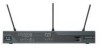
... levels of router LEDs, ports, and other components. • Installation-Provides information on safety, preventing damage, unpacking, and preparing for service technicians with your router. • Troubleshooting-Describes how to additional information and material. 78-5373-04 Cisco 800 Series Routers Hardware Installation Guide vii Conceptual information is to connect the router to the network as quickly as installing, mounting, and verifying the connections to your router. • ISDN...
... levels of router LEDs, ports, and other components. • Installation-Provides information on safety, preventing damage, unpacking, and preparing for service technicians with your router. • Troubleshooting-Describes how to additional information and material. 78-5373-04 Cisco 800 Series Routers Hardware Installation Guide vii Conceptual information is to connect the router to the network as quickly as installing, mounting, and verifying the connections to your router. • ISDN...
Hardware Installation Guide
Page 10
... following address: Cisco Systems Attn: Customer Document Ordering 170 West Tasman Drive San Jose, CA 95134-9883 We appreciate your comments. A current list of your document or by calling 1 800 553-NETS (6387). psirt@cisco.com Cisco 800 Series Routers Hardware Installation Guide x 78-5373-04 Documentation Feedback You can submit comments by using the response card (if present) behind the front cover of security...
... following address: Cisco Systems Attn: Customer Document Ordering 170 West Tasman Drive San Jose, CA 95134-9883 We appreciate your comments. A current list of your document or by calling 1 800 553-NETS (6387). psirt@cisco.com Cisco 800 Series Routers Hardware Installation Guide x 78-5373-04 Documentation Feedback You can submit comments by using the response card (if present) behind the front cover of security...
Hardware Installation Guide
Page 11
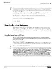
Cisco Technical Support Website The Cisco Technical Support Website provides online documents and tools for service. Search results show command output. PSIRT can work from encrypted information that is the one that you can register at this public key server list: http://pgp.mit.edu:11371/pks/lookup?search=psirt%40cisco.com&op=index&exact=on the Cisco Technical Support Website requires a Cisco.com user ID and password. Choose Cisco Product...
Cisco Technical Support Website The Cisco Technical Support Website provides online documents and tools for service. Search results show command output. PSIRT can work from encrypted information that is the one that you can register at this public key server list: http://pgp.mit.edu:11371/pks/lookup?search=psirt%40cisco.com&op=index&exact=on the Cisco Technical Support Website requires a Cisco.com user ID and password. Choose Cisco Product...
Hardware Installation Guide
Page 16
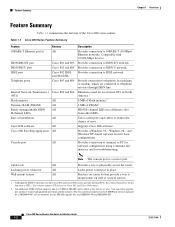
... connected to Cisco 802 and Cisco 804 routers. 2. Table 1-1 Cisco 800 Series Feature Summary Feature 10BASE-T Ethernet port(s) ISDN BRI S/T port ISDN BRI U port IDSL port Telephone ports Internal Network Termination 1 (NT1) Flash memory Dynamic RAM (DRAM) Easily distinguishable ISDN B-channel LEDs Ease of DRAM.2 ISDN B-channel LEDs in a different color from other LEDs. Compatible with 10/100-Mbps devices. Eliminates need for basic configurations. Color-coded ports and cables to physically secure the router. Provides a Windows 95-, Windows...
... connected to Cisco 802 and Cisco 804 routers. 2. Table 1-1 Cisco 800 Series Feature Summary Feature 10BASE-T Ethernet port(s) ISDN BRI S/T port ISDN BRI U port IDSL port Telephone ports Internal Network Termination 1 (NT1) Flash memory Dynamic RAM (DRAM) Easily distinguishable ISDN B-channel LEDs Ease of DRAM.2 ISDN B-channel LEDs in a different color from other LEDs. Compatible with 10/100-Mbps devices. Eliminates need for basic configurations. Color-coded ports and cables to physically secure the router. Provides a Windows 95-, Windows...

Hardware Installation Guide
Page 18
... section show the back panel of each of the Cisco 800 series routers. HUB/NO HUB button (for Ethernet port) Console port Determines cable Connect PC or type for Ethernet terminal. ISDN BRI S/T port Connect to physically secure router. Ethernet port Connect Ethernet network device. Power switch l = On. = Standby or no power output. 11666 LINK HUB NO HUB ETHERNET 10 BASE T Cisco 801 CONSOLE ISDN S/T Cable lock Use cable lock to external NT1 or ISDN wall jack. Warning If the...
... section show the back panel of each of the Cisco 800 series routers. HUB/NO HUB button (for Ethernet port) Console port Determines cable Connect PC or type for Ethernet terminal. ISDN BRI S/T port Connect to physically secure router. Ethernet port Connect Ethernet network device. Power switch l = On. = Standby or no power output. 11666 LINK HUB NO HUB ETHERNET 10 BASE T Cisco 801 CONSOLE ISDN S/T Cable lock Use cable lock to external NT1 or ISDN wall jack. Warning If the...

Hardware Installation Guide
Page 19
...port 0) Determines cable type for Ethernet device connection. Ethernet port Connect Ethernet network device. LINK HUB NO HUB ETHERNET 10 BASE T CONSOLE Cisco 802 ISDN U Cable lock Use cable lock to ISDN wall jack. Console port Connect PC or terminal. PHONE 1 2 Locking power connector Connect power supply. 78-5373-04 Cisco 800 Series Routers Hardware Installation Guide 1-5 Power switch l = On. = Standby or no power output. Console port Connect PC or terminal. Chapter 1 Overview Back Panels Figure 1-5 Cisco 802 Router Back Panel Link LED Indicates state of Ethernet port...
...port 0) Determines cable type for Ethernet device connection. Ethernet port Connect Ethernet network device. LINK HUB NO HUB ETHERNET 10 BASE T CONSOLE Cisco 802 ISDN U Cable lock Use cable lock to ISDN wall jack. Console port Connect PC or terminal. PHONE 1 2 Locking power connector Connect power supply. 78-5373-04 Cisco 800 Series Routers Hardware Installation Guide 1-5 Power switch l = On. = Standby or no power output. Console port Connect PC or terminal. Chapter 1 Overview Back Panels Figure 1-5 Cisco 802 Router Back Panel Link LED Indicates state of Ethernet port...

Hardware Installation Guide
Page 20
... device connection. Ethernet port Connect Ethernet network device. IDSL port Connect to ISDN wall jack. Power switch l = On. = Standby or no power output. 11669 Cable lock Use cable lock to telephone, fax machine, or modem. Console port Connect PC or terminal. ISDN BRI U port Connect to IDSL wall jack. Telephone ports Connect to physically secure router. Cisco 804 CONSOLE ISDN U Console port Connect PC or terminal. Figure 1-8 Cisco 802 IDSL Router Back Panel Link LED Indicates state of Ethernet port. Locking power connector Connect power supply...
... device connection. Ethernet port Connect Ethernet network device. IDSL port Connect to ISDN wall jack. Power switch l = On. = Standby or no power output. 11669 Cable lock Use cable lock to telephone, fax machine, or modem. Console port Connect PC or terminal. ISDN BRI U port Connect to IDSL wall jack. Telephone ports Connect to physically secure router. Cisco 804 CONSOLE ISDN U Console port Connect PC or terminal. Figure 1-8 Cisco 802 IDSL Router Back Panel Link LED Indicates state of Ethernet port. Locking power connector Connect power supply...

Hardware Installation Guide
Page 21
... the connection has a problem. Cisco 804 IDSL CONSOLE IDSL Console port Connect PC or terminal. On when the Ethernet device is connected. Table 1-3 LED Functions LED Color OK Green NT1 Green LINE LAN LAN RXD LAN TXD LKØ, LK1, LK2, LK3 Green Green Green Green Green ETHERNET Green 1, 2, 3, 4 Function On when power is supplied to physically secure router. Blinks when an Ethernet port sends a packet. Off when the Ethernet device is not connected. See the "Troubleshooting" chapter. 78-5373-04 Cisco 800 Series Routers Hardware Installation Guide...
... the connection has a problem. Cisco 804 IDSL CONSOLE IDSL Console port Connect PC or terminal. On when the Ethernet device is connected. Table 1-3 LED Functions LED Color OK Green NT1 Green LINE LAN LAN RXD LAN TXD LKØ, LK1, LK2, LK3 Green Green Green Green Green ETHERNET Green 1, 2, 3, 4 Function On when power is supplied to physically secure router. Blinks when an Ethernet port sends a packet. Off when the Ethernet device is not connected. See the "Troubleshooting" chapter. 78-5373-04 Cisco 800 Series Routers Hardware Installation Guide...
Hardware Installation Guide
Page 24
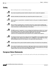
... a nonremovable, connect-one-time-only plug) must not connect the port to a public network that has a standby/off switch, turn the power to standby and unplug the power cord. Warning Read the installation instructions before you must be handled according to all national laws and regulations. Any hardwired connection (other than by PTO staff or suitably trained engineers. Some LAN and WAN ports both use RJ...
... a nonremovable, connect-one-time-only plug) must not connect the port to a public network that has a standby/off switch, turn the power to standby and unplug the power cord. Warning Read the installation instructions before you must be handled according to all national laws and regulations. Any hardwired connection (other than by PTO staff or suitably trained engineers. Some LAN and WAN ports both use RJ...

Hardware Installation Guide
Page 26
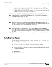
... 2 Order an ISDN BRI line from your telephone service provider. Table 2-1 Router Box Contents • Power cord (black) • Desktop power supply • Console cable (light blue) • DB-9-to-RJ-45 adapter for use with your router. Unpacking Your Router Table 2-1 lists the items that your router came in Appendix B, "Specifications and Cables." Connecting the port to a public network that follows the European Union standards. Warning If...
... 2 Order an ISDN BRI line from your telephone service provider. Table 2-1 Router Box Contents • Power cord (black) • Desktop power supply • Console cable (light blue) • DB-9-to-RJ-45 adapter for use with your router. Unpacking Your Router Table 2-1 lists the items that your router came in Appendix B, "Specifications and Cables." Connecting the port to a public network that follows the European Union standards. Warning If...
Hardware Installation Guide
Page 27
... to connect each device (usually this cable is drywall, you instead need to the router. 2. Connect a terminal or PC to the power source. 7. If you plan to configure the software using the command-line interface [CLI] or for software configuration using a terminal or PC connected to the ISDN wall jack. Be aware of North America, ask your telephone service provider if you must provide an external Network Termination...
... to connect each device (usually this cable is drywall, you instead need to the router. 2. Connect a terminal or PC to the power source. 7. If you plan to configure the software using the command-line interface [CLI] or for software configuration using a terminal or PC connected to the ISDN wall jack. Be aware of North America, ask your telephone service provider if you must provide an external Network Termination...
Hardware Installation Guide
Page 28
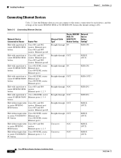
.../TO Ethernet port PC button Cisco 804 IDSL router: Ethernet port 1 Hub without equivalent Cisco 803 and 804 to router HUB/NO routers: HUB button Ethernet ports 1, 2, 3 Hub without equivalent Cisco 804 IDSL router: to the router, connections for each device, and the settings of the router HUB/NO HUB or TO HUB/TO PC button (the default setting is IN). Installing Your Router Chapter 2 Installation Connecting Ethernet Devices Table 2-2 lists the Ethernet devices you can connect to router TO HUB/TO Ethernet ports 2, 3, 4 PC button Ethernet Cable Type1 Router...
.../TO Ethernet port PC button Cisco 804 IDSL router: Ethernet port 1 Hub without equivalent Cisco 803 and 804 to router HUB/NO routers: HUB button Ethernet ports 1, 2, 3 Hub without equivalent Cisco 804 IDSL router: to the router, connections for each device, and the settings of the router HUB/NO HUB or TO HUB/TO PC button (the default setting is IN). Installing Your Router Chapter 2 Installation Connecting Ethernet Devices Table 2-2 lists the Ethernet devices you can connect to router TO HUB/TO Ethernet ports 2, 3, 4 PC button Ethernet Cable Type1 Router...
Hardware Installation Guide
Page 44
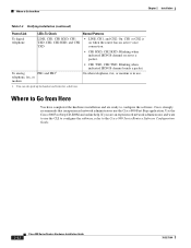
... the router has an active voice connection. • CH1 RXD, CH2 RXD: Blinking when indicated ISDN B channel receives a packet. Use the Cisco 800 Fast Step CD-ROM and online help. To analog PH1 and PH21 telephone, fax, or modem • CH1 TXD, CH2 TXD: Blinking when indicated ISDN B channel sends a packet. Where to Go from Here Chapter 2 Installation Table 2-4 Verifying Installation (continued) Power/Link LEDs...
... the router has an active voice connection. • CH1 RXD, CH2 RXD: Blinking when indicated ISDN B channel receives a packet. Use the Cisco 800 Fast Step CD-ROM and online help. To analog PH1 and PH21 telephone, fax, or modem • CH1 TXD, CH2 TXD: Blinking when indicated ISDN B channel sends a packet. Where to Go from Here Chapter 2 Installation Table 2-4 Verifying Installation (continued) Power/Link LEDs...

Hardware Installation Guide
Page 47
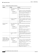
... you supply your own cable, make sure you have cabled the devices correctly, see Table 2-2 in Chapter 2, "Installation." • Improperly functioning network interface card (NIC) on the back panel is not physically damaged. If it is off . Table 3-2 Problems After First Startup Symptom Problem Solutions No link to Cisco 801 and Cisco 803 Routers" section in the "Connecting an ISDN Line to an Ethernet device. (On Cisco 801, Cisco 802...
... you supply your own cable, make sure you have cabled the devices correctly, see Table 2-2 in Chapter 2, "Installation." • Improperly functioning network interface card (NIC) on the back panel is not physically damaged. If it is off . Table 3-2 Problems After First Startup Symptom Problem Solutions No link to Cisco 801 and Cisco 803 Routers" section in the "Connecting an ISDN Line to an Ethernet device. (On Cisco 801, Cisco 802...
Hardware Installation Guide
Page 48
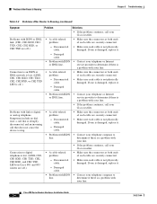
... "Connecting a Digital connected cable. No link to digital telephone. • One of each cable are securely connected. • Make sure each cable is not physically damaged. Damaged cable. Improperly IDSL port correctly, see the "Connecting an connected cable. ISDN Line" or "Connecting an IDSL Line" - Damaged cable. "Installation." • Make sure the connectors at both ends of each cable are securely connected. • Make sure each cable is not physically damaged. Cisco 800 Series Routers Hardware Installation Guide...
... "Connecting a Digital connected cable. No link to digital telephone. • One of each cable are securely connected. • Make sure each cable is not physically damaged. Damaged cable. Improperly IDSL port correctly, see the "Connecting an connected cable. ISDN Line" or "Connecting an IDSL Line" - Damaged cable. "Installation." • Make sure the connectors at both ends of each cable are securely connected. • Make sure each cable is not physically damaged. Cisco 800 Series Routers Hardware Installation Guide...
Hardware Installation Guide
Page 50
... securely connected. • Make sure each cable is a problem with your line. • If the problem continues, call your line. Disconnected cable. - Problems After Router Is Running Chapter 3 Troubleshooting Table 3-3 Problems After Router Is Running (continued) Symptom Problem Solutions • If the problem continues, call your Cisco reseller. Problems with link to determine if there is not physically damaged. service provider to digital or analog telephone. Damaged cable. • Make...
... securely connected. • Make sure each cable is a problem with your line. • If the problem continues, call your line. Disconnected cable. - Problems After Router Is Running Chapter 3 Troubleshooting Table 3-3 Problems After Router Is Running (continued) Symptom Problem Solutions • If the problem continues, call your Cisco reseller. Problems with link to determine if there is not physically damaged. service provider to digital or analog telephone. Damaged cable. • Make...
Hardware Installation Guide
Page 59
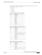
... 1 Unused 2 Unused 3 TXD+ 4 RXD+ 5 RXD- 6 TXD- 7 Unused 8 Unused Table B-9 ISDN BRI U Connector Pinouts (RJ-45) Pin Function 1 Unused 2 Unused 3 Unused 4 U interface network connection (Tip) 5 U interface network connection (Ring) 6 Unused 7 Unused 8 Unused Table B-10 IDSL Connector Pinouts (RJ-45) Pin Function 1 Unused 2 Unused 3 Unused 4 IDSL interface network connection (Tip) Cisco 800 Series Routers Hardware Installation Guide B-5 The default parameters for the console port are as a data communications equipment (DCE) device.
... 1 Unused 2 Unused 3 TXD+ 4 RXD+ 5 RXD- 6 TXD- 7 Unused 8 Unused Table B-9 ISDN BRI U Connector Pinouts (RJ-45) Pin Function 1 Unused 2 Unused 3 Unused 4 U interface network connection (Tip) 5 U interface network connection (Ring) 6 Unused 7 Unused 8 Unused Table B-10 IDSL Connector Pinouts (RJ-45) Pin Function 1 Unused 2 Unused 3 Unused 4 IDSL interface network connection (Tip) Cisco 800 Series Routers Hardware Installation Guide B-5 The default parameters for the console port are as a data communications equipment (DCE) device.
Hardware Installation Guide
Page 68
... to 2-13 ISDN S/T port described 1-2 illustrated 1-5 ISDN U port described 1-2 illustrated 1-5, 1-6 L LEDs IN-2 Cisco 800 Series Routers Hardware Installation Guide described 1-7 illustrated 1-3 to 1-6 locking power connector, illustrated 1-4 to 1-7 M modem, connecting 2-15 mounting the router 2-18 N network device button settings 2-6 to 2-7 NT1 feature 1-2 P panels, illustrated 1-4 to 1-7 PC, connecting 2-9, 2-17 port connector pinouts B-2 to B-6 ports for specific routers 1-3 power problems 3-2 specifications B-1 verifying 2-20 power supply connecting 2-18 power switch illustrated 1-4 to...
... to 2-13 ISDN S/T port described 1-2 illustrated 1-5 ISDN U port described 1-2 illustrated 1-5, 1-6 L LEDs IN-2 Cisco 800 Series Routers Hardware Installation Guide described 1-7 illustrated 1-3 to 1-6 locking power connector, illustrated 1-4 to 1-7 M modem, connecting 2-15 mounting the router 2-18 N network device button settings 2-6 to 2-7 NT1 feature 1-2 P panels, illustrated 1-4 to 1-7 PC, connecting 2-9, 2-17 port connector pinouts B-2 to B-6 ports for specific routers 1-3 power problems 3-2 specifications B-1 verifying 2-20 power supply connecting 2-18 power switch illustrated 1-4 to...

Hardware Installation Guide
Page 69
Index S S/T interface A-1 safety warnings 2-2 server, connecting 2-9 settings, network devices 2-6 to 2-7 specifications cabling B-6 system B-1 startup problems 3-2 T table mounting 2-18 telephone connecting 2-14, 2-15 ports described 1-2 illustrated 1-5, 1-6 temperature specifications B-1 terminal, connecting 2-17 TO HUB/TO PC button illustrated 1-6 to 1-7 settings 2-6 to 2-20 warnings, installation 2-2 weight specifications B-1 workstation, connecting 2-9 U U interface A-1 United Kingdom master sockets 2-16 78-5373-04 Cisco 800 Series Routers Hardware Installation Guide IN-3 to 2-4 V...
Index S S/T interface A-1 safety warnings 2-2 server, connecting 2-9 settings, network devices 2-6 to 2-7 specifications cabling B-6 system B-1 startup problems 3-2 T table mounting 2-18 telephone connecting 2-14, 2-15 ports described 1-2 illustrated 1-5, 1-6 temperature specifications B-1 terminal, connecting 2-17 TO HUB/TO PC button illustrated 1-6 to 1-7 settings 2-6 to 2-20 warnings, installation 2-2 weight specifications B-1 workstation, connecting 2-9 U U interface A-1 United Kingdom master sockets 2-16 78-5373-04 Cisco 800 Series Routers Hardware Installation Guide IN-3 to 2-4 V...


