Hardware Installation Guide
Page 4
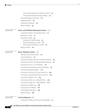
... for Wall Mounting 3-2 Mounting the Router on a Wall 3-2 Mounting the PoE Module on a Wall 3-5 What to Do Next 3-6 Router Cabling Procedures 4-1 Cabling for Nonwireless Routers 4-2 Typical Installations 4-2 Connecting the Radio Antennas to the Wireless Router 4-6 Connecting the Power-over-Ethernet Module (Optional) 4-7 ...SHDSL Line 4-19 Connecting the AC Adapter 4-21 Verifying Router Operations 4-24 What to Do Next 4-25 Initial Configuration 5-1 Installing Cisco Router and Security Device Manager 5-1 Cisco 850 Series and Cisco 870 Series Access Routers Hardware Installation Guide 4 OL-5331...
... for Wall Mounting 3-2 Mounting the Router on a Wall 3-2 Mounting the PoE Module on a Wall 3-5 What to Do Next 3-6 Router Cabling Procedures 4-1 Cabling for Nonwireless Routers 4-2 Typical Installations 4-2 Connecting the Radio Antennas to the Wireless Router 4-6 Connecting the Power-over-Ethernet Module (Optional) 4-7 ...SHDSL Line 4-19 Connecting the AC Adapter 4-21 Verifying Router Operations 4-24 What to Do Next 4-25 Initial Configuration 5-1 Installing Cisco Router and Security Device Manager 5-1 Cisco 850 Series and Cisco 870 Series Access Routers Hardware Installation Guide 4 OL-5331...

Hardware Installation Guide
Page 27
The integrated cable below the cable number label, consisting of four RJ-45 connectors organized by a plastic clip, is not shown in this illustration. Figure 1-13 Power-over -Ethernet Module Front Panel 2 TO ROUTER 3210 48VDC 121040 1 Power adapter input jack 2 Cable numbers associated ...the back panel. Figure 1-12 1 Power-over -Ethernet Module Back Panel 1 2 PWR 0 1 2 3 TO LAN 121039 1 LED indicators and Ethernet ports for connecting powered devices 2 Power indicator OL-5331-01 Cisco 850 Series and Cisco 870 Series Access Routers Hardware Installation Guide 1-13 doing so...
The integrated cable below the cable number label, consisting of four RJ-45 connectors organized by a plastic clip, is not shown in this illustration. Figure 1-13 Power-over -Ethernet Module Front Panel 2 TO ROUTER 3210 48VDC 121040 1 Power adapter input jack 2 Cable numbers associated ...the back panel. Figure 1-12 1 Power-over -Ethernet Module Back Panel 1 2 PWR 0 1 2 3 TO LAN 121039 1 LED indicators and Ethernet ports for connecting powered devices 2 Power indicator OL-5331-01 Cisco 850 Series and Cisco 870 Series Access Routers Hardware Installation Guide 1-13 doing so...

Hardware Installation Guide
Page 28
Hardware Features Figure 1-14 Installing the PoE Module Chapter 1 Product Overview 1 1 LEFT 0 SN: XXXNNNNXXXX LAN FE0 FE1 FE2 FE3 Cisco 871W WAN FE4 RESET CONSOLE AUX +5,+12 VDC RIGHT / PRIMARY 2 PWR 7 0 1 2 3 To LAN 5 3 6 4 1 Cisco 870 series router 2 Ethernet cables on the PoE module (four RJ-45 connectors in series) 3 PoE module 4 PoE power adapter 5 Router power adapter 6 PoE power plug 7 Router power plug 122351 1-14 Cisco 850 Series and Cisco 870 Series Access Routers Hardware Installation Guide OL-5331-01
Hardware Features Figure 1-14 Installing the PoE Module Chapter 1 Product Overview 1 1 LEFT 0 SN: XXXNNNNXXXX LAN FE0 FE1 FE2 FE3 Cisco 871W WAN FE4 RESET CONSOLE AUX +5,+12 VDC RIGHT / PRIMARY 2 PWR 7 0 1 2 3 To LAN 5 3 6 4 1 Cisco 870 series router 2 Ethernet cables on the PoE module (four RJ-45 connectors in series) 3 PoE module 4 PoE power adapter 5 Router power adapter 6 PoE power plug 7 Router power plug 122351 1-14 Cisco 850 Series and Cisco 870 Series Access Routers Hardware Installation Guide OL-5331-01

Hardware Installation Guide
Page 36
... Routers Cisco 851 and Cisco 857 and Item Cisco 871 Routers Cisco 877 Routers Cisco 876 Router Cisco 878 Router Ethernet cable(s) DSL1 cable ISDN4 S/T cable 2 Not applicable Not applicable 1 12 Not applicable 1 13 Optional 1 13 Optional Console cable Console-auxiliary5 cable 1 Optional 1 Optional 1 Optional 1 Optional Power adapter Power cord6 Cisco documentation7 1 1 1 1 1 1 1 1 1 1 1 1 Cisco Router and Security Device 1 1 1 1 Manager (SDM) software CD Swivel-mount dipole antenna Cisco 851: Cisco 857: 2 2 (wireless router...
... Routers Cisco 851 and Cisco 857 and Item Cisco 871 Routers Cisco 877 Routers Cisco 876 Router Cisco 878 Router Ethernet cable(s) DSL1 cable ISDN4 S/T cable 2 Not applicable Not applicable 1 12 Not applicable 1 13 Optional 1 13 Optional Console cable Console-auxiliary5 cable 1 Optional 1 Optional 1 Optional 1 Optional Power adapter Power cord6 Cisco documentation7 1 1 1 1 1 1 1 1 1 1 1 1 Cisco Router and Security Device 1 1 1 1 Manager (SDM) software CD Swivel-mount dipole antenna Cisco 851: Cisco 857: 2 2 (wireless router...
Hardware Installation Guide
Page 37
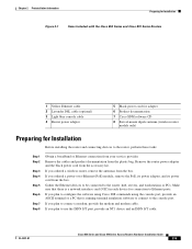
...Cisco 850 Series and Cisco 870 Series Routers 1 Yellow Ethernet cable 2 Lavender DSL cable (optional) 3 Light blue console cable 4 Router power adapter 5 Black power cord for adapter 6 Product documentation 7 Cisco SDM software CD 8 Swivel-mount dipole antenna (wireless router ...router power adapter and the black power cord from the plastic bag. If you plan to the router: hub, servers, and workstations or PCs. Gather the Ethernet devices to be connected to connect a modem, provide the modem and modem cable. If you ordered a wireless router, remove the antennas from your service...
...Cisco 850 Series and Cisco 870 Series Routers 1 Yellow Ethernet cable 2 Lavender DSL cable (optional) 3 Light blue console cable 4 Router power adapter 5 Black power cord for adapter 6 Product documentation 7 Cisco SDM software CD 8 Swivel-mount dipole antenna (wireless router ...router power adapter and the black power cord from the plastic bag. If you plan to the router: hub, servers, and workstations or PCs. Gather the Ethernet devices to be connected to connect a modem, provide the modem and modem cable. If you ordered a wireless router, remove the antennas from your service...

Hardware Installation Guide
Page 40
... supported, the strain on the power adapter cable could pull the router from the connector on the router back panel. • Do not install the router, PoE module, or power supplies next to the Ethernet ports on the router. • The power supply must provide the screws. Cisco 850 Series and Cisco 870 Series Access Routers Hardware Installation Guide 3-2 OL-5331...
... supported, the strain on the power adapter cable could pull the router from the connector on the router back panel. • Do not install the router, PoE module, or power supplies next to the Ethernet ports on the router. • The power supply must provide the screws. Cisco 850 Series and Cisco 870 Series Access Routers Hardware Installation Guide 3-2 OL-5331...

Hardware Installation Guide
Page 41
OL-5331-01 Cisco 850 Series and Cisco 870 Series Access Routers Hardware Installation Guide 3-3 Chapter 3 Router and PoE Module Mounting Procedures Figure 3-1 Mounting Brackets on the Bottom of the Router 1 2 Mounting on a Wall 3 127042 1 Distance between two top mounting brackets 3 Vertical distance between the top mounting (near the front panel) brackets and the bottom bracket 2 Midpoint between the two top mounting brackets (near the front panel) Figure 3-2 shows the locations of the mounting screws and the router mounting brackets, and the placement of the power adapter.
OL-5331-01 Cisco 850 Series and Cisco 870 Series Access Routers Hardware Installation Guide 3-3 Chapter 3 Router and PoE Module Mounting Procedures Figure 3-1 Mounting Brackets on the Bottom of the Router 1 2 Mounting on a Wall 3 127042 1 Distance between two top mounting brackets 3 Vertical distance between the top mounting (near the front panel) brackets and the bottom bracket 2 Midpoint between the two top mounting brackets (near the front panel) Figure 3-2 shows the locations of the mounting screws and the router mounting brackets, and the placement of the power adapter.

Hardware Installation Guide
Page 42
... the bottom 7 Distance between the screw head and the wall (1/8 in . screws 5 Maximum distance between the router and the power adapter (6 ft. [1.8 m]) 2 Distance between the top set of screws on the wall 6 Horizontal surface on the wall [0.32 cm]) 4 Mounting brackets Cisco 850 Series and Cisco 870 Series Access Routers Hardware Installation Guide 3-4 OL-5331-01
... the bottom 7 Distance between the screw head and the wall (1/8 in . screws 5 Maximum distance between the router and the power adapter (6 ft. [1.8 m]) 2 Distance between the top set of screws on the wall 6 Horizontal surface on the wall [0.32 cm]) 4 Mounting brackets Cisco 850 Series and Cisco 870 Series Access Routers Hardware Installation Guide 3-4 OL-5331-01

Hardware Installation Guide
Page 43
...midpoint, measure a vertical distance of the mounting brackets. Place the power adapter on a horizontal surface. (See Figure 3-2.) Mounting the PoE Module on a Wall The PoE module can be mounted on which you wish to mount the router. Anchor the screws into the latches of 5.55 in . (0.... between the screw head and the wall for the bottom mounting screw, and then drill a hole. OL-5331-01 Cisco 850 Series and Cisco 870 Series Access Routers Hardware Installation Guide 3-5 Chapter 3 Router and PoE Module Mounting Procedures Mounting on a Wall Perform the following steps to mount the...
...midpoint, measure a vertical distance of the mounting brackets. Place the power adapter on a horizontal surface. (See Figure 3-2.) Mounting the PoE Module on a Wall The PoE module can be mounted on which you wish to mount the router. Anchor the screws into the latches of 5.55 in . (0.... between the screw head and the wall for the bottom mounting screw, and then drill a hole. OL-5331-01 Cisco 850 Series and Cisco 870 Series Access Routers Hardware Installation Guide 3-5 Chapter 3 Router and PoE Module Mounting Procedures Mounting on a Wall Perform the following steps to mount the...

Hardware Installation Guide
Page 45
...Connecting a G.SHDSL Line, page 4-19 • Connecting the AC Adapter, page 4-21 • Verifying Router Operations, page 4-24 • What to Do Next, page 4-...Cisco 851, Cisco 857, Cisco 871, Cisco 876, Cisco 877, and Cisco 878 routers. OL-5331-01 Cisco 850 Series and Cisco 870 Series Access Routers Hardware Installation Guide 4-1 CH A P T E R 4 Router Cabling Procedures This chapter describes the cabling procedures for Nonwireless Routers, page 4-2 • Typical Installations, page 4-2 • Connecting the Radio Antennas to the Wireless Router, page 4-6 • Connecting the Power...
...Connecting a G.SHDSL Line, page 4-19 • Connecting the AC Adapter, page 4-21 • Verifying Router Operations, page 4-24 • What to Do Next, page 4-...Cisco 851, Cisco 857, Cisco 871, Cisco 876, Cisco 877, and Cisco 878 routers. OL-5331-01 Cisco 850 Series and Cisco 870 Series Access Routers Hardware Installation Guide 4-1 CH A P T E R 4 Router Cabling Procedures This chapter describes the cabling procedures for Nonwireless Routers, page 4-2 • Typical Installations, page 4-2 • Connecting the Radio Antennas to the Wireless Router, page 4-6 • Connecting the Power...

Hardware Installation Guide
Page 47
Chapter 4 Router Cabling Procedures Figure 4-1 Typical Installation of a Cisco 851 or Cisco 871 Router Typical Installations 1 LEFT 0 SN: XXXNNNNXXXX LAN FE4 0 FE3 1 FE2 2 FE1 3 Cisco 871W WAN FE4 RESET CONSOLE AUX +5,+12 VDC RIGHT / PRIMARY 1 2 3 4 5 1X 2X 1X 2X 1 Internet 1 Ethernet connection to an external switch 2 Ethernet connection to a PC 3 WAN connection using a broadband modem to the Internet 4 Console port 5 Power adapter 122237 OL-5331-01 Cisco 850 Series and Cisco 870 Series Access Routers Hardware Installation Guide 4-3
Chapter 4 Router Cabling Procedures Figure 4-1 Typical Installation of a Cisco 851 or Cisco 871 Router Typical Installations 1 LEFT 0 SN: XXXNNNNXXXX LAN FE4 0 FE3 1 FE2 2 FE1 3 Cisco 871W WAN FE4 RESET CONSOLE AUX +5,+12 VDC RIGHT / PRIMARY 1 2 3 4 5 1X 2X 1X 2X 1 Internet 1 Ethernet connection to an external switch 2 Ethernet connection to a PC 3 WAN connection using a broadband modem to the Internet 4 Console port 5 Power adapter 122237 OL-5331-01 Cisco 850 Series and Cisco 870 Series Access Routers Hardware Installation Guide 4-3

Hardware Installation Guide
Page 48
Typical Installations Figure 4-2 Typical Installation of a Cisco 857 or Cisco 877 Router Chapter 4 Router Cabling Procedures 122238 LEFT SN: XXXNNNNXXXX ETHERNET LAN FE3 4 FE2 3 FE1 2 FE0 1 Cisco 877W ADSLoPOTS RESET CONSOLE AUX +5,+12 VDC RIGHT / PRIMARY 1 2 3 4 5 1X 2X 1X 2X 1 1 Ethernet connection to an external switch 2 Ethernet connection to a PC 3 ADSL-over-POTS connection 4 Console port 5 Power adapter Cisco 850 Series and Cisco 870 Series Access Routers Hardware Installation Guide 4-4 OL-5331-01
Typical Installations Figure 4-2 Typical Installation of a Cisco 857 or Cisco 877 Router Chapter 4 Router Cabling Procedures 122238 LEFT SN: XXXNNNNXXXX ETHERNET LAN FE3 4 FE2 3 FE1 2 FE0 1 Cisco 877W ADSLoPOTS RESET CONSOLE AUX +5,+12 VDC RIGHT / PRIMARY 1 2 3 4 5 1X 2X 1X 2X 1 1 Ethernet connection to an external switch 2 Ethernet connection to a PC 3 ADSL-over-POTS connection 4 Console port 5 Power adapter Cisco 850 Series and Cisco 870 Series Access Routers Hardware Installation Guide 4-4 OL-5331-01

Hardware Installation Guide
Page 49
Chapter 4 Router Cabling Procedures Figure 4-3 Typical Installation of a Cisco 876 Router Typical Installations 122239 LEFT Cisco 876W SN: XXXNNNNXXXX LAN FE0 FE1 FE2 FE3 ISDN S/T ADSL o ISDN RESET CONSOLE AUX +5,+12 VDC RIGHT / PRIMARY 1 23 45 6 1X 2X 1X 2X 1 1 Ethernet connection to an external switch 2 Ethernet connection to a PC 3 ISDN S/T connection 4 ADSL-over-ISDN connection 5 Console port 6 Power adapter OL-5331-01 Cisco 850 Series and Cisco 870 Series Access Routers Hardware Installation Guide 4-5
Chapter 4 Router Cabling Procedures Figure 4-3 Typical Installation of a Cisco 876 Router Typical Installations 122239 LEFT Cisco 876W SN: XXXNNNNXXXX LAN FE0 FE1 FE2 FE3 ISDN S/T ADSL o ISDN RESET CONSOLE AUX +5,+12 VDC RIGHT / PRIMARY 1 23 45 6 1X 2X 1X 2X 1 1 Ethernet connection to an external switch 2 Ethernet connection to a PC 3 ISDN S/T connection 4 ADSL-over-ISDN connection 5 Console port 6 Power adapter OL-5331-01 Cisco 850 Series and Cisco 870 Series Access Routers Hardware Installation Guide 4-5

Hardware Installation Guide
Page 50
... Router Chapter 4 Router Cabling Procedures LEFT Cisco 878W SN: XXXNNNNXXXX LAN FE0 FE1 FE2 FE3 ISDN S/T G.SHDSL RESET CONSOLE AUX +5,+12 VDC RIGHT / PRIMARY 1 23 45 6 122240 1X 2X 1X 2X 1 1 Ethernet connection to an external switch 2 Ethernet connection to a PC 3 ISDN S/T connection 4 G.SHDSL connection 5 Console port 6 Power adapter Connecting the Radio Antennas to the Wireless Router...
... Router Chapter 4 Router Cabling Procedures LEFT Cisco 878W SN: XXXNNNNXXXX LAN FE0 FE1 FE2 FE3 ISDN S/T G.SHDSL RESET CONSOLE AUX +5,+12 VDC RIGHT / PRIMARY 1 23 45 6 122240 1X 2X 1X 2X 1 1 Ethernet connection to an external switch 2 Ethernet connection to a PC 3 ISDN S/T connection 4 G.SHDSL connection 5 Console port 6 Power adapter Connecting the Radio Antennas to the Wireless Router...

Hardware Installation Guide
Page 51
...the PoE module to the router, connect the Ethernet devices to the ports on the PoE module, rather than to the router. to the PoE module, see the "Connecting the AC Adapter" section. For information about connecting the power supply to 2-second delay... cables on the PoE module to the router After you may notice a 1- Chapter 4 Router Cabling Procedures Connecting the Power-over-Ethernet Module (Optional) Connecting the Power-over-Ethernet Module (Optional) If you purchased a power-over -Ethernet Module to the Router 2 1 1 LEFT 0 5 Cisco 871W LAN FE0 FE1 FE2 FE3 0 1 ...
...the PoE module to the router, connect the Ethernet devices to the ports on the PoE module, rather than to the router. to the PoE module, see the "Connecting the AC Adapter" section. For information about connecting the power supply to 2-second delay... cables on the PoE module to the router After you may notice a 1- Chapter 4 Router Cabling Procedures Connecting the Power-over-Ethernet Module (Optional) Connecting the Power-over-Ethernet Module (Optional) If you purchased a power-over -Ethernet Module to the Router 2 1 1 LEFT 0 5 Cisco 871W LAN FE0 FE1 FE2 FE3 0 1 ...

Hardware Installation Guide
Page 65
... TN power systems. Statement 19 Warning This product relies on the building's installation for short-circuit (overcurrent) protection. Warning The device is used on the phase conductors (all Cisco 850 series and Cisco 870 series routers. Chapter 4 Router Cabling Procedures Figure 4-17 Primary Protection Device Location Telecom Service Overhead Service Entrance Home or Business Connecting the AC Adapter Router...
... TN power systems. Statement 19 Warning This product relies on the building's installation for short-circuit (overcurrent) protection. Warning The device is used on the phase conductors (all Cisco 850 series and Cisco 870 series routers. Chapter 4 Router Cabling Procedures Figure 4-17 Primary Protection Device Location Telecom Service Overhead Service Entrance Home or Business Connecting the AC Adapter Router...

Hardware Installation Guide
Page 66
Connecting the AC Adapter Chapter 4 Router Cabling Procedures Figure 4-18 Connecting the AC Adapter (No PoE Module) 1 LEFT 0 1 Cisco 871W LAN WAN FE0 FE1 FE2 FE3 FE4 RESET CONSOLE AUX +5,+12 VDC RIGHT / PRIMARY 2 5 3 4 117975 1 Router 2 Router input jack 3 Power cord 4 Desktop power adapter 5 Power cord plug 4-22 Cisco 850 Series and Cisco 870 Series Access Routers Hardware Installation Guide OL-5331-01
Connecting the AC Adapter Chapter 4 Router Cabling Procedures Figure 4-18 Connecting the AC Adapter (No PoE Module) 1 LEFT 0 1 Cisco 871W LAN WAN FE0 FE1 FE2 FE3 FE4 RESET CONSOLE AUX +5,+12 VDC RIGHT / PRIMARY 2 5 3 4 117975 1 Router 2 Router input jack 3 Power cord 4 Desktop power adapter 5 Power cord plug 4-22 Cisco 850 Series and Cisco 870 Series Access Routers Hardware Installation Guide OL-5331-01

Hardware Installation Guide
Page 67
... 0 SN: XXXNNNNXXXX LAN FE0 FE1 FE2 FE3 Cisco 871W WAN FE4 RESET CONSOLE AUX +5,+12 VDC RIGHT / PRIMARY 2 PWR 7 0 1 2 3 To LAN 5 3 6 4 122351 1 Router 2 Ethernet cables on the PoE module 3 PoE module 4 PoE module power adapter 5 Router power adapter 6 PoE module power adapter plug 7 Router power adapter plug Perform the following steps to connect power to the router and to the PoE module: Step 1 Step 2 Step...
... 0 SN: XXXNNNNXXXX LAN FE0 FE1 FE2 FE3 Cisco 871W WAN FE4 RESET CONSOLE AUX +5,+12 VDC RIGHT / PRIMARY 2 PWR 7 0 1 2 3 To LAN 5 3 6 4 122351 1 Router 2 Ethernet cables on the PoE module 3 PoE module 4 PoE module power adapter 5 Router power adapter 6 PoE module power adapter plug 7 Router power adapter plug Perform the following steps to connect power to the router and to the PoE module: Step 1 Step 2 Step...


