
Hardware Installation Guide
Page 16
... 122245 SN: XXXNNNNXXXX LAN FE4 0 FE3 1 FE2 2 FE1 3 Cisco 851W WAN FE4 RESET CONSOLE AUX +5,+12 VDC Figure 1-3 Cisco 871 Router Back Panel with Antennas 1 LEFT 0 SN: XXXNNNNXXXX LAN FE0 FE1 FE2 FE3 Cisco 871W WAN FE4 RESET CONSOLE AUX +5,+12 VDC RIGHT / PRIMARY 122241 Cisco 850 Series and Cisco 870 Series Access Routers Hardware Installation Guide 1-2 OL-5331-01
... 122245 SN: XXXNNNNXXXX LAN FE4 0 FE3 1 FE2 2 FE1 3 Cisco 851W WAN FE4 RESET CONSOLE AUX +5,+12 VDC Figure 1-3 Cisco 871 Router Back Panel with Antennas 1 LEFT 0 SN: XXXNNNNXXXX LAN FE0 FE1 FE2 FE3 Cisco 871W WAN FE4 RESET CONSOLE AUX +5,+12 VDC RIGHT / PRIMARY 122241 Cisco 850 Series and Cisco 870 Series Access Routers Hardware Installation Guide 1-2 OL-5331-01

Hardware Installation Guide
Page 18
General Descriptions of the Router Models Chapter 1 Product Overview Figure 1-5 Cisco 857 Router Back Panel, with Antenna Installed 122242 SN: XXXNNNNXXXX LAN FE0 FE1 FE2 FE3 Cisco 857W ADSLoPOTS RESET CONSOLE AUX +5,+12 VDC Figure 1-6 Cisco 877 Router Back Panel, with Antennas Installed 127093 LEFT SN: XXXNNNNXXXX LAN FE0 FE1 FE2 FE3 Cisco 877W ADSLoPOTS RESET CONSOLE AUX +5,+12 VDC RIGHT/PRIMARY Cisco 850 Series and Cisco 870 Series Access Routers Hardware Installation Guide 1-4 OL-5331-01
General Descriptions of the Router Models Chapter 1 Product Overview Figure 1-5 Cisco 857 Router Back Panel, with Antenna Installed 122242 SN: XXXNNNNXXXX LAN FE0 FE1 FE2 FE3 Cisco 857W ADSLoPOTS RESET CONSOLE AUX +5,+12 VDC Figure 1-6 Cisco 877 Router Back Panel, with Antennas Installed 127093 LEFT SN: XXXNNNNXXXX LAN FE0 FE1 FE2 FE3 Cisco 877W ADSLoPOTS RESET CONSOLE AUX +5,+12 VDC RIGHT/PRIMARY Cisco 850 Series and Cisco 870 Series Access Routers Hardware Installation Guide 1-4 OL-5331-01

Hardware Installation Guide
Page 19
...service provider (ISP) over -ISDN routing device. DATA ADSL ISDN WLAN ETHERNET LAN 0123 CISCO 800 SERIES 122349 Figure 1-8 Cisco 876 Router Back Panel, with a built-in switch • One ADSL-over-POTS port • One RJ-45 console port Cisco 876 ADSL-over-ISDN Router The Cisco 876 router... is an asymmetric digital subscriber line (ADSL)-over an ADSL interface. Figure 1-7 Cisco 876 Router Front Panel OK CD - The router has an integrated 4-port Ethernet switch for the LAN and an...
...service provider (ISP) over -ISDN routing device. DATA ADSL ISDN WLAN ETHERNET LAN 0123 CISCO 800 SERIES 122349 Figure 1-8 Cisco 876 Router Back Panel, with a built-in switch • One ADSL-over-POTS port • One RJ-45 console port Cisco 876 ADSL-over-ISDN Router The Cisco 876 router... is an asymmetric digital subscriber line (ADSL)-over an ADSL interface. Figure 1-7 Cisco 876 Router Front Panel OK CD - The router has an integrated 4-port Ethernet switch for the LAN and an...

Hardware Installation Guide
Page 21
... 1 FE2 2 FE1 3 ISDN S/T G.SHDSL RESET CONSOLE AUX +5,+12 VDC RIGHT / PRIMARY 122244 Router Ports on the Cisco 878 Back Panel The Cisco 878 router has the following ports on Cisco 876 routers only. ADSL-over-POTS port Cisco 857 and Cisco 877 routers only. Can be connected to other network devices,...01 Cisco 850 Series and Cisco 870 Series Access Routers Hardware Installation Guide 1-7 Can be used for dial backup on the back panel: • Four 10/100BASE-T RJ-45 Fast Ethernet LAN ports with 10/100-Mbps devices. Provides connection to the ISDN service provider...
... 1 FE2 2 FE1 3 ISDN S/T G.SHDSL RESET CONSOLE AUX +5,+12 VDC RIGHT / PRIMARY 122244 Router Ports on the Cisco 878 Back Panel The Cisco 878 router has the following ports on Cisco 876 routers only. ADSL-over-POTS port Cisco 857 and Cisco 877 routers only. Can be connected to other network devices,...01 Cisco 850 Series and Cisco 870 Series Access Routers Hardware Installation Guide 1-7 Can be used for dial backup on the back panel: • Four 10/100BASE-T RJ-45 Fast Ethernet LAN ports with 10/100-Mbps devices. Provides connection to the ISDN service provider...

Hardware Installation Guide
Page 22
...Cisco IOS Advanced IP Services image or Enterprise Services image. Expandable by 8, 16, or 32 MB, up to a wireless LAN using Kensington lockdown equipment. Expandable by using IEEE 802.11b/g standards. Wall-mount feature Brackets for powered devices (such as a virtual auxiliary port (using the command-line interface (CLI). Integrated...Synchronous dynamic RAM (SDRAM) Cisco 850 series routers: 64 MB of SDRAM on board. Cisco 870 series routers: 128 MB of flash memory for dial backup and remote management. Router Reset button Resets the router configuration to a maximum ...
...Cisco IOS Advanced IP Services image or Enterprise Services image. Expandable by 8, 16, or 32 MB, up to a wireless LAN using Kensington lockdown equipment. Expandable by using IEEE 802.11b/g standards. Wall-mount feature Brackets for powered devices (such as a virtual auxiliary port (using the command-line interface (CLI). Integrated...Synchronous dynamic RAM (SDRAM) Cisco 850 series routers: 64 MB of SDRAM on board. Cisco 870 series routers: 128 MB of flash memory for dial backup and remote management. Router Reset button Resets the router configuration to a maximum ...

Hardware Installation Guide
Page 23
...: AAANNNNXXXX LAN FE0 FE1 FE2 FE3 Cisco 878 ISDN S/T G.SHDSL RESET CONSOLE AUX +5,+9 VDC SN: AAANNNNXXXX LED Indicators on the Routers The router LEDs that indicate status or activity on the router are located on the Routers LED OK WAN LNK WAN RXD Color...overview of the hardware features of Cisco 850 series and Cisco 870 series routers and includes the following topics: • Serial Number Location • LED Indicators on the Routers • Integrated 802.11b/g Radio Module (Wireless Models Only) • Supported Cisco Radio Antennas (Wireless Models Only) • External...
...: AAANNNNXXXX LAN FE0 FE1 FE2 FE3 Cisco 878 ISDN S/T G.SHDSL RESET CONSOLE AUX +5,+9 VDC SN: AAANNNNXXXX LED Indicators on the Routers The router LEDs that indicate status or activity on the router are located on the Routers LED OK WAN LNK WAN RXD Color...overview of the hardware features of Cisco 850 series and Cisco 870 series routers and includes the following topics: • Serial Number Location • LED Indicators on the Routers • Integrated 802.11b/g Radio Module (Wireless Models Only) • Supported Cisco Radio Antennas (Wireless Models Only) • External...

Hardware Installation Guide
Page 28
Hardware Features Figure 1-14 Installing the PoE Module Chapter 1 Product Overview 1 1 LEFT 0 SN: XXXNNNNXXXX LAN FE0 FE1 FE2 FE3 Cisco 871W WAN FE4 RESET CONSOLE AUX +5,+12 VDC RIGHT / PRIMARY 2 PWR 7 0 1 2 3 To LAN 5 3 6 4 1 Cisco 870 series router 2 Ethernet cables on the PoE module (four RJ-45 connectors in series) 3 PoE module 4 PoE power adapter 5 Router power adapter 6 PoE power plug 7 Router power plug 122351 1-14 Cisco 850 Series and Cisco 870 Series Access Routers Hardware Installation Guide OL-5331-01
Hardware Features Figure 1-14 Installing the PoE Module Chapter 1 Product Overview 1 1 LEFT 0 SN: XXXNNNNXXXX LAN FE0 FE1 FE2 FE3 Cisco 871W WAN FE4 RESET CONSOLE AUX +5,+12 VDC RIGHT / PRIMARY 2 PWR 7 0 1 2 3 To LAN 5 3 6 4 1 Cisco 870 series router 2 Ethernet cables on the PoE module (four RJ-45 connectors in series) 3 PoE module 4 PoE power adapter 5 Router power adapter 6 PoE power plug 7 Router power plug 122351 1-14 Cisco 850 Series and Cisco 870 Series Access Routers Hardware Installation Guide OL-5331-01

Hardware Installation Guide
Page 29
Chapter 1 Product Overview Figure 1-15 Connecting the PoE Module to the Router Hardware Features 1 LEFT 0 3 21 Cisco 871W SN: XXXNNNNXXXX LAN WAN FE0 FE1 FE2 FE3 FE4 RESET CONSOLE AUX +5,+12 VDC RIGHT / PRIMARY 142607 PWR 4 0 1 2 3 To LAN 1 Cisco 870 series router 2 RJ-45 Ethernet ports on the router 3 Four RJ-45 Ethernet plugs, in series, from the PoE module (plug these into the Ethernet ports on the router) 4 PoE module OL-5331-01 Cisco 850 Series and Cisco 870 Series Access Routers Hardware Installation Guide 1-15
Chapter 1 Product Overview Figure 1-15 Connecting the PoE Module to the Router Hardware Features 1 LEFT 0 3 21 Cisco 871W SN: XXXNNNNXXXX LAN WAN FE0 FE1 FE2 FE3 FE4 RESET CONSOLE AUX +5,+12 VDC RIGHT / PRIMARY 142607 PWR 4 0 1 2 3 To LAN 1 Cisco 870 series router 2 RJ-45 Ethernet ports on the router 3 Four RJ-45 Ethernet plugs, in series, from the PoE module (plug these into the Ethernet ports on the router) 4 PoE module OL-5331-01 Cisco 850 Series and Cisco 870 Series Access Routers Hardware Installation Guide 1-15

Hardware Installation Guide
Page 30
...Memory • SDRAM Flash Memory Flash memory stores the image of onboard flash memory. 1-16 Cisco 850 Series and Cisco 870 Series Access Routers Hardware Installation Guide OL-5331-01 The router provides two onboard StrataFlash devices, one with 16 MB and the other with 4 MB of ...administratively down Power provided to the device Fault detected in power delivery Power denied to the Router Chapter 1 Product Overview 1 LEFT 0 SN: XXXNNNNXXXX LAN FE0 FE1 FE2 FE3 Cisco 871W WAN FE4 RESET CONSOLE AUX +5,+12 VDC RIGHT / PRIMARY 142608 LED Indicators on the PoE Module Table ...
...Memory • SDRAM Flash Memory Flash memory stores the image of onboard flash memory. 1-16 Cisco 850 Series and Cisco 870 Series Access Routers Hardware Installation Guide OL-5331-01 The router provides two onboard StrataFlash devices, one with 16 MB and the other with 4 MB of ...administratively down Power provided to the device Fault detected in power delivery Power denied to the Router Chapter 1 Product Overview 1 LEFT 0 SN: XXXNNNNXXXX LAN FE0 FE1 FE2 FE3 Cisco 871W WAN FE4 RESET CONSOLE AUX +5,+12 VDC RIGHT / PRIMARY 142608 LED Indicators on the PoE Module Table ...

Hardware Installation Guide
Page 47
Chapter 4 Router Cabling Procedures Figure 4-1 Typical Installation of a Cisco 851 or Cisco 871 Router Typical Installations 1 LEFT 0 SN: XXXNNNNXXXX LAN FE4 0 FE3 1 FE2 2 FE1 3 Cisco 871W WAN FE4 RESET CONSOLE AUX +5,+12 VDC RIGHT / PRIMARY 1 2 3 4 5 1X 2X 1X 2X 1 Internet 1 Ethernet connection to an external switch 2 Ethernet connection to a PC 3 WAN connection using a broadband modem to the Internet 4 Console port 5 Power adapter 122237 OL-5331-01 Cisco 850 Series and Cisco 870 Series Access Routers Hardware Installation Guide 4-3
Chapter 4 Router Cabling Procedures Figure 4-1 Typical Installation of a Cisco 851 or Cisco 871 Router Typical Installations 1 LEFT 0 SN: XXXNNNNXXXX LAN FE4 0 FE3 1 FE2 2 FE1 3 Cisco 871W WAN FE4 RESET CONSOLE AUX +5,+12 VDC RIGHT / PRIMARY 1 2 3 4 5 1X 2X 1X 2X 1 Internet 1 Ethernet connection to an external switch 2 Ethernet connection to a PC 3 WAN connection using a broadband modem to the Internet 4 Console port 5 Power adapter 122237 OL-5331-01 Cisco 850 Series and Cisco 870 Series Access Routers Hardware Installation Guide 4-3

Hardware Installation Guide
Page 48
Typical Installations Figure 4-2 Typical Installation of a Cisco 857 or Cisco 877 Router Chapter 4 Router Cabling Procedures 122238 LEFT SN: XXXNNNNXXXX ETHERNET LAN FE3 4 FE2 3 FE1 2 FE0 1 Cisco 877W ADSLoPOTS RESET CONSOLE AUX +5,+12 VDC RIGHT / PRIMARY 1 2 3 4 5 1X 2X 1X 2X 1 1 Ethernet connection to an external switch 2 Ethernet connection to a PC 3 ADSL-over-POTS connection 4 Console port 5 Power adapter Cisco 850 Series and Cisco 870 Series Access Routers Hardware Installation Guide 4-4 OL-5331-01
Typical Installations Figure 4-2 Typical Installation of a Cisco 857 or Cisco 877 Router Chapter 4 Router Cabling Procedures 122238 LEFT SN: XXXNNNNXXXX ETHERNET LAN FE3 4 FE2 3 FE1 2 FE0 1 Cisco 877W ADSLoPOTS RESET CONSOLE AUX +5,+12 VDC RIGHT / PRIMARY 1 2 3 4 5 1X 2X 1X 2X 1 1 Ethernet connection to an external switch 2 Ethernet connection to a PC 3 ADSL-over-POTS connection 4 Console port 5 Power adapter Cisco 850 Series and Cisco 870 Series Access Routers Hardware Installation Guide 4-4 OL-5331-01

Hardware Installation Guide
Page 49
Chapter 4 Router Cabling Procedures Figure 4-3 Typical Installation of a Cisco 876 Router Typical Installations 122239 LEFT Cisco 876W SN: XXXNNNNXXXX LAN FE0 FE1 FE2 FE3 ISDN S/T ADSL o ISDN RESET CONSOLE AUX +5,+12 VDC RIGHT / PRIMARY 1 23 45 6 1X 2X 1X 2X 1 1 Ethernet connection to an external switch 2 Ethernet connection to a PC 3 ISDN S/T connection 4 ADSL-over-ISDN connection 5 Console port 6 Power adapter OL-5331-01 Cisco 850 Series and Cisco 870 Series Access Routers Hardware Installation Guide 4-5
Chapter 4 Router Cabling Procedures Figure 4-3 Typical Installation of a Cisco 876 Router Typical Installations 122239 LEFT Cisco 876W SN: XXXNNNNXXXX LAN FE0 FE1 FE2 FE3 ISDN S/T ADSL o ISDN RESET CONSOLE AUX +5,+12 VDC RIGHT / PRIMARY 1 23 45 6 1X 2X 1X 2X 1 1 Ethernet connection to an external switch 2 Ethernet connection to a PC 3 ISDN S/T connection 4 ADSL-over-ISDN connection 5 Console port 6 Power adapter OL-5331-01 Cisco 850 Series and Cisco 870 Series Access Routers Hardware Installation Guide 4-5

Hardware Installation Guide
Page 50
... being mounted on a desk, orient the antenna straight up. Connecting the Radio Antennas to the Wireless Router Figure 4-4 Typical Installation of a Cisco 878 Router Chapter 4 Router Cabling Procedures LEFT Cisco 878W SN: XXXNNNNXXXX LAN FE0 FE1 FE2 FE3 ISDN S/T G.SHDSL RESET CONSOLE AUX +5,+12 VDC RIGHT / PRIMARY 1 23 45 6 122240 1X 2X 1X 2X 1 1 Ethernet connection to...
... being mounted on a desk, orient the antenna straight up. Connecting the Radio Antennas to the Wireless Router Figure 4-4 Typical Installation of a Cisco 878 Router Chapter 4 Router Cabling Procedures LEFT Cisco 878W SN: XXXNNNNXXXX LAN FE0 FE1 FE2 FE3 ISDN S/T G.SHDSL RESET CONSOLE AUX +5,+12 VDC RIGHT / PRIMARY 1 23 45 6 122240 1X 2X 1X 2X 1 1 Ethernet connection to...

Hardware Installation Guide
Page 51
... (Optional) Connecting the Power-over-Ethernet Module (Optional) If you purchased a power-over -Ethernet Module to the Router 2 1 1 LEFT 0 5 Cisco 871W LAN FE0 FE1 FE2 FE3 0 1 2 3 To LAN WAN FE4 RESET CONSOLE AUX +5,+12 VDC 3 PWR 4 RIGHT / PRIMARY 121035 1 Router 4 PoE module 2 Router Ethernet ports 5 Plastic cable guard 3 Ethernet cables connecting the PoE module to the...
... (Optional) Connecting the Power-over-Ethernet Module (Optional) If you purchased a power-over -Ethernet Module to the Router 2 1 1 LEFT 0 5 Cisco 871W LAN FE0 FE1 FE2 FE3 0 1 2 3 To LAN WAN FE4 RESET CONSOLE AUX +5,+12 VDC 3 PWR 4 RIGHT / PRIMARY 121035 1 Router 4 PoE module 2 Router Ethernet ports 5 Plastic cable guard 3 Ethernet cables connecting the PoE module to the...

Hardware Installation Guide
Page 52
... a Server, PC, or Workstation 2 1 1 LEFT 0 Cisco 871W LAN WAN FE4 0 FE3 1 FE2 2 FE1 3 FE4 RESET CONSOLE AUX +5,+12 VDC 3 RIGHT / PRIMARY 4 5 117971 1 Router 2 Yellow Ethernet cable 3 Built-in Ethernet switch port, follow the steps given after Figure 4-6, which shows a Cisco 871 router connected to a PC. Connecting a Server, PC, or Workstation Chapter 4 Router Cabling Procedures Connecting a Server, PC...
... a Server, PC, or Workstation 2 1 1 LEFT 0 Cisco 871W LAN WAN FE4 0 FE3 1 FE2 2 FE1 3 FE4 RESET CONSOLE AUX +5,+12 VDC 3 RIGHT / PRIMARY 4 5 117971 1 Router 2 Yellow Ethernet cable 3 Built-in Ethernet switch port, follow the steps given after Figure 4-6, which shows a Cisco 871 router connected to a PC. Connecting a Server, PC, or Workstation Chapter 4 Router Cabling Procedures Connecting a Server, PC...

Hardware Installation Guide
Page 54
... steps to connect the router to an external Ethernet switch: Step 1 Step 2 Step 3 Connect one end of the yellow Ethernet cable to the available port on the Ethernet switch. 4-10 Cisco 850 Series and Cisco 870 Series Access Routers Hardware Installation Guide OL-...5331-01 Connecting an External Ethernet Switch (Optional) Figure 4-7 Connecting to an Ethernet Switch Chapter 4 Router Cabling Procedures 1 LEFT 0 Cisco 871W LAN WAN FE4 0 FE3 1 FE2 2 FE1 3 FE4 RESET CONSOLE AUX +5,+12 VDC 1 RIGHT / PRIMARY 117972 SYSTEM RPS MODE STATUS UTIL DUPLX SPEED 1 1X ...
... steps to connect the router to an external Ethernet switch: Step 1 Step 2 Step 3 Connect one end of the yellow Ethernet cable to the available port on the Ethernet switch. 4-10 Cisco 850 Series and Cisco 870 Series Access Routers Hardware Installation Guide OL-...5331-01 Connecting an External Ethernet Switch (Optional) Figure 4-7 Connecting to an Ethernet Switch Chapter 4 Router Cabling Procedures 1 LEFT 0 Cisco 871W LAN WAN FE4 0 FE3 1 FE2 2 FE1 3 FE4 RESET CONSOLE AUX +5,+12 VDC 1 RIGHT / PRIMARY 117972 SYSTEM RPS MODE STATUS UTIL DUPLX SPEED 1 1X ...
Hardware Installation Guide
Page 55
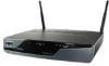
... to an available port on the modem. Figure 4-8 Connecting to a Broadband Modem 1 LEFT 0 Cisco 871W LAN WAN FE0 FE1 FE2 FE3 FE4 RESET CONSOLE AUX +5,+12 VDC 1 RIGHT / PRIMARY ETHERNET POWER 575-LRE Cisco 117973 ACTIVITY WAN 2 1 Ethernet WAN port on the router 2 Available port on the modem Perform the following steps to connect the...
... to an available port on the modem. Figure 4-8 Connecting to a Broadband Modem 1 LEFT 0 Cisco 871W LAN WAN FE0 FE1 FE2 FE3 FE4 RESET CONSOLE AUX +5,+12 VDC 1 RIGHT / PRIMARY ETHERNET POWER 575-LRE Cisco 117973 ACTIVITY WAN 2 1 Ethernet WAN port on the router 2 Available port on the modem Perform the following steps to connect the...
Hardware Installation Guide
Page 56
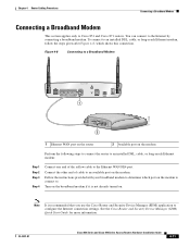
...terminal or PC to a terminal or PC. 4-12 Cisco 850 Series and Cisco 870 Series Access Routers Hardware Installation Guide OL-5331-01 Figure 4-9 Connecting a Terminal or PC to the Console Port 1 LEFT 0 Cisco 871W LAN WAN FE4 0 FE3 1 FE2 2 FE1 3 FE4 RESET CONSOLE AUX +5,+12 VDC RIGHT / PRIMARY 1 2 117974... the light blue cable to troubleshoot problems with the router. Connecting a Terminal or PC to the Console Port Chapter 4 Router Cabling Procedures Connecting a Terminal or PC to the Console Port The console port is a service port to which you can connect a terminal or ...
...terminal or PC to a terminal or PC. 4-12 Cisco 850 Series and Cisco 870 Series Access Routers Hardware Installation Guide OL-5331-01 Figure 4-9 Connecting a Terminal or PC to the Console Port 1 LEFT 0 Cisco 871W LAN WAN FE4 0 FE3 1 FE2 2 FE1 3 FE4 RESET CONSOLE AUX +5,+12 VDC RIGHT / PRIMARY 1 2 117974... the light blue cable to troubleshoot problems with the router. Connecting a Terminal or PC to the Console Port Chapter 4 Router Cabling Procedures Connecting a Terminal or PC to the Console Port The console port is a service port to which you can connect a terminal or ...

Hardware Installation Guide
Page 57
...to the Console Port SN: XXXNNNNXXXX LAN FE0 FE1 FE2 FE3 1 Cisco 857W ADSLoPOTS RESET CONSOLE AUX +5,+12 VDC 2 3 4 5 123 ABC DEF 456 GHI JKL MNO 789 PQRS TUV WXYZ * 0 OPER # 127049 OL-5331-01 1 Router console port 2 Router modem cable 3 Available port on an async modem 4 Wall jack ...Cisco 870 series routers support the dial backup function, which allows a user to connect an analog modem to the console port as a backup link to the console port, you will need an optional router modem cable. Note To connect an analog modem to the WAN port in case the ADSL service...
...to the Console Port SN: XXXNNNNXXXX LAN FE0 FE1 FE2 FE3 1 Cisco 857W ADSLoPOTS RESET CONSOLE AUX +5,+12 VDC 2 3 4 5 123 ABC DEF 456 GHI JKL MNO 789 PQRS TUV WXYZ * 0 OPER # 127049 OL-5331-01 1 Router console port 2 Router modem cable 3 Available port on an async modem 4 Wall jack ...Cisco 870 series routers support the dial backup function, which allows a user to connect an analog modem to the console port as a backup link to the console port, you will need an optional router modem cable. Note To connect an analog modem to the WAN port in case the ADSL service...

Hardware Installation Guide
Page 59
... orange ISDN S/T cable to the telephone line port on the splitter. Chapter 4 Router Cabling Procedures Connecting an ISDN S/T Port Figure 4-11 Connecting the ISDN S/T Port to the ISDN Service Provider LEFT Cisco 876W LAN FE0 FE1 FE2 FE3 ISDN S/T ADSL o ISDN RESET CONSOLE AUX +5,+12 VDC RIGHT / PRIMARY 1 2 5 127094 3 4 67 8 1 One end of the...
... orange ISDN S/T cable to the telephone line port on the splitter. Chapter 4 Router Cabling Procedures Connecting an ISDN S/T Port Figure 4-11 Connecting the ISDN S/T Port to the ISDN Service Provider LEFT Cisco 876W LAN FE0 FE1 FE2 FE3 ISDN S/T ADSL o ISDN RESET CONSOLE AUX +5,+12 VDC RIGHT / PRIMARY 1 2 5 127094 3 4 67 8 1 One end of the...


