User Guide
Page 7
1 C H A P T E R Preface vii Audience vii New and Changed Information vii Organization viii Conventions viii Related Documentation xi Obtaining Documentation xiii World Wide Web xiii Documentation CD-ROM xiii Ordering Documentation xiv Obtaining Technical Assistance xiv Cisco Connection Online xiv Technical Assistance Center xv Documentation Feedback xvi Product Overview 1-1 Interface Modules and Port Adapters 1-2 Route Processors 1-3 Switch Modules 1-3 Power Supplies 1-4 Fan Assembly 1-5 CONTENTS 78-6134-03 Catalyst 8540 Chassis Installation Guide v
1 C H A P T E R Preface vii Audience vii New and Changed Information vii Organization viii Conventions viii Related Documentation xi Obtaining Documentation xiii World Wide Web xiii Documentation CD-ROM xiii Ordering Documentation xiv Obtaining Technical Assistance xiv Cisco Connection Online xiv Technical Assistance Center xv Documentation Feedback xvi Product Overview 1-1 Interface Modules and Port Adapters 1-2 Route Processors 1-3 Switch Modules 1-3 Power Supplies 1-4 Fan Assembly 1-5 CONTENTS 78-6134-03 Catalyst 8540 Chassis Installation Guide v

User Guide
Page 8
... the AC Power Supply 2-8 Connecting the DC Power Supply 2-10 Power Supply LEDs 2-12 Maintaining the Chassis 3-1 Replacing Power Supplies 3-2 Tools Required 3-2 Removing the AC Power Supply 3-3 Removing the DC Power Supply 3-5 Replacing the Fan Assembly 3-6 Tools Required 3-7 Removing the Fan Assembly 3-8 Installing the Fan Assembly 3-9 Chassis and Power Supply Specifications A-1 Translated Safety Warnings B-1 Safety Information Referral Warning B-1 Power Supply Bay Warning B-3 Ground Connection Warning B-4 Catalyst 8540 Chassis...
... the AC Power Supply 2-8 Connecting the DC Power Supply 2-10 Power Supply LEDs 2-12 Maintaining the Chassis 3-1 Replacing Power Supplies 3-2 Tools Required 3-2 Removing the AC Power Supply 3-3 Removing the DC Power Supply 3-5 Replacing the Fan Assembly 3-6 Tools Required 3-7 Removing the Fan Assembly 3-8 Installing the Fan Assembly 3-9 Chassis and Power Supply Specifications A-1 Translated Safety Warnings B-1 Safety Information Referral Warning B-1 Power Supply Bay Warning B-3 Ground Connection Warning B-4 Catalyst 8540 Chassis...
User Guide
Page 10
... to prepare your site for installation, install the chassis, and connect power at your site Chapter 3 Maintaining the Describes maintenance procedures Chassis Appendix A Chassis and Power Supply Specifications Describes the chassis and power supply specifications Appendix B Translated Safety Lists the warnings in the publication. Catalyst 8540 Chassis Installation Guide viii 78-6134-03 Cautions use the following...
... to prepare your site for installation, install the chassis, and connect power at your site Chapter 3 Maintaining the Describes maintenance procedures Chassis Appendix A Chassis and Power Supply Specifications Describes the chassis and power supply specifications Appendix B Translated Safety Lists the warnings in the publication. Catalyst 8540 Chassis Installation Guide viii 78-6134-03 Cautions use the following...
User Guide
Page 19
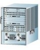
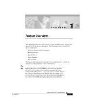
... the chassis components. CH A P T E R 1 Product Overview This chapter describes the Catalyst 8540, a 13-slot, modular chassis, and provides an overview of a fully populated Catalyst 8540 chassis. The following sections describe the chassis components: • Interface Modules and Port Adapters • Route Processors • Switch Modules • Power Supplies • Fan Assembly The chassis ships populated specifically to the...
... the chassis components. CH A P T E R 1 Product Overview This chapter describes the Catalyst 8540, a 13-slot, modular chassis, and provides an overview of a fully populated Catalyst 8540 chassis. The following sections describe the chassis components: • Interface Modules and Port Adapters • Route Processors • Switch Modules • Power Supplies • Fan Assembly The chassis ships populated specifically to the...

User Guide
Page 20
.... Interface Modules and Port Adapters Figure 1-1 Catalyst 8540 Chassis Slots 0-3: Interface modules Slot 4: Route processor Slots 5-7: Switch modules Slot 8: Redundant route processor Slots 9-12: Interface modules Chapter 1 Product Overview 32600 INPUT FAN OUTPUT OK OK FAIL INPUT FAN OK OK Power supply 0 Power supply 1 Interface Modules and Port Adapters The Catalyst 8540 interface modules and port adapters provide ports...
.... Interface Modules and Port Adapters Figure 1-1 Catalyst 8540 Chassis Slots 0-3: Interface modules Slot 4: Route processor Slots 5-7: Switch modules Slot 8: Redundant route processor Slots 9-12: Interface modules Chapter 1 Product Overview 32600 INPUT FAN OUTPUT OK OK FAIL INPUT FAN OK OK Power supply 0 Power supply 1 Interface Modules and Port Adapters The Catalyst 8540 interface modules and port adapters provide ports...
User Guide
Page 22
..., > 55° C). Each power supply contains a power supply fan. Each power supply monitors its own internal temperature and voltages. In the event of a failure of one power supply, the redundant power option ensures uninterrupted operation. If an internal power supply temperature or voltage reaches the alarm level, the Output Fail LED may turn the power switch on the console. Catalyst 8540 Chassis Installation Guide 1-4 78...
..., > 55° C). Each power supply contains a power supply fan. Each power supply monitors its own internal temperature and voltages. In the event of a failure of one power supply, the redundant power option ensures uninterrupted operation. If an internal power supply temperature or voltage reaches the alarm level, the Output Fail LED may turn the power switch on the console. Catalyst 8540 Chassis Installation Guide 1-4 78...
User Guide
Page 25
This chapter contains the following sections: • Site Planning • Rack-Mounting the Chassis • Installing Power Supplies • Connecting Power to the Chassis Warning Before you should know before working with the system. Site Planning Planning the proper location and layout of your... and Safety Guide. Equipment placed in an inadequately ventilated area can make chassis panels inaccessible and difficult to maintain. 78-6134-03 Catalyst 8540 Chassis Installation Guide 2-1 In addition, poor equipment placement can cause system overtemperature conditions.
This chapter contains the following sections: • Site Planning • Rack-Mounting the Chassis • Installing Power Supplies • Connecting Power to the Chassis Warning Before you should know before working with the system. Site Planning Planning the proper location and layout of your... and Safety Guide. Equipment placed in an inadequately ventilated area can make chassis panels inaccessible and difficult to maintain. 78-6134-03 Catalyst 8540 Chassis Installation Guide 2-1 In addition, poor equipment placement can cause system overtemperature conditions.

User Guide
Page 31
... DC power supply, follow these steps: Step 1 Grasp the power supply handle with one hand. Place your other hand underneath to install a power supply. Warning Keep hands and fingers out of the supply. (See Figure 2-4.) Figure 2-4 Handling a Power Supply 32607 INPUT OK FAN OUTPUT OK FAIL 78-6134-03 Catalyst 8540 Chassis Installation Guide 2-7 Chapter 2 Installing the Chassis Installing Power Supplies Installing Power Supplies You...
... DC power supply, follow these steps: Step 1 Grasp the power supply handle with one hand. Place your other hand underneath to install a power supply. Warning Keep hands and fingers out of the supply. (See Figure 2-4.) Figure 2-4 Handling a Power Supply 32607 INPUT OK FAN OUTPUT OK FAIL 78-6134-03 Catalyst 8540 Chassis Installation Guide 2-7 Chapter 2 Installing the Chassis Installing Power Supplies Installing Power Supplies You...
User Guide
Page 32
..., install the power supply in the left power supply bay. This section contains the following topics: • Connecting the AC Power Supply • Connecting the DC Power Supply Note Install proper grounding to the chassis. Connecting Power to the Chassis Chapter 2 Installing the Chassis Step 2 Push the power supply into the power cord connection of one AC power supply. (See Figure 2-5.) Catalyst 8540 Chassis Installation Guide...
..., install the power supply in the left power supply bay. This section contains the following topics: • Connecting the AC Power Supply • Connecting the DC Power Supply Note Install proper grounding to the chassis. Connecting Power to the Chassis Chapter 2 Installing the Chassis Step 2 Push the power supply into the power cord connection of one AC power supply. (See Figure 2-5.) Catalyst 8540 Chassis Installation Guide...

User Guide
Page 33
Connect the redundant AC power supply cord to an input line other end of the redundant power supply. Chapter 2 Installing the Chassis Figure 2-5 Power Cord Connections Connecting Power to the Chassis 33013 Step 2 Step 3 Step 4 Power supply 0 Power supply 1 Power cord connection Power cord connection Connect the other than the initial power supply line. 78-6134-03 Catalyst 8540 Chassis Installation Guide 2-9 Plug the power cord into the power cord connection of the AC power supply cord to an input line.
Connect the redundant AC power supply cord to an input line other end of the redundant power supply. Chapter 2 Installing the Chassis Figure 2-5 Power Cord Connections Connecting Power to the Chassis 33013 Step 2 Step 3 Step 4 Power supply 0 Power supply 1 Power cord connection Power cord connection Connect the other than the initial power supply line. 78-6134-03 Catalyst 8540 Chassis Installation Guide 2-9 Plug the power cord into the power cord connection of the AC power supply cord to an input line.

User Guide
Page 34
... Chassis Chapter 2 Installing the Chassis Step 5 Step 6 Turn the power switch of the terminal block cover. (See Figure 2-6.) Figure 2-6 DC Power Supply (Terminal Block Cover Shown) 17116 Terminal block cover Power switch o INPUT OK FAN OUTPUT OK FAIL LEDs Captive screw 2-10 Catalyst 8540 Chassis Installation Guide 78-6134-03 Connecting Power to the input line. See Table 2-1 on ( | ).
... Chassis Chapter 2 Installing the Chassis Step 5 Step 6 Turn the power switch of the terminal block cover. (See Figure 2-6.) Figure 2-6 DC Power Supply (Terminal Block Cover Shown) 17116 Terminal block cover Power switch o INPUT OK FAN OUTPUT OK FAIL LEDs Captive screw 2-10 Catalyst 8540 Chassis Installation Guide 78-6134-03 Connecting Power to the input line. See Table 2-1 on ( | ).
User Guide
Page 35
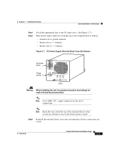
...the terminal block cover after ensuring that you do not obstruct access to "−" terminal Figure 2-7 DC Power Supply (Terminal Block Cover Not Shown) Terminal block 15708 Power o switch INPUT OK FAN OUTPUT OK FAIL LEDs Warning When installing the unit, the ground connection must always be made...wires from the top of the terminal block so that all wire connections are secure. 78-6134-03 Catalyst 8540 Chassis Installation Guide 2-11 Chapter 2 Installing the Chassis Connecting Power to the Chassis Step 4 Step 5 Attach the appropriate lugs to the DC-input wires. (See ...
...the terminal block cover after ensuring that you do not obstruct access to "−" terminal Figure 2-7 DC Power Supply (Terminal Block Cover Not Shown) Terminal block 15708 Power o switch INPUT OK FAN OUTPUT OK FAIL LEDs Warning When installing the unit, the ground connection must always be made...wires from the top of the terminal block so that all wire connections are secure. 78-6134-03 Catalyst 8540 Chassis Installation Guide 2-11 Chapter 2 Installing the Chassis Connecting Power to the Chassis Step 4 Step 5 Attach the appropriate lugs to the DC-input wires. (See ...
User Guide
Page 36
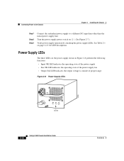
... LED indicates the output voltage is outside of proper range Figure 2-8 Power Supply LEDs 32599 INPUT OK FAN OUTPUT OK FAIL LEDs 2-12 Catalyst 8540 Chassis Installation Guide 78-6134-03 Turn the power supply power switch on ( | ). (See Figure 2-7.) Verify power supply operation by checking the power supply LEDs. Connecting Power to the Chassis Chapter 2 Installing the Chassis Step 7 Step 8 Step 9 Connect...
... LED indicates the output voltage is outside of proper range Figure 2-8 Power Supply LEDs 32599 INPUT OK FAN OUTPUT OK FAIL LEDs 2-12 Catalyst 8540 Chassis Installation Guide 78-6134-03 Turn the power supply power switch on ( | ). (See Figure 2-7.) Verify power supply operation by checking the power supply LEDs. Connecting Power to the Chassis Chapter 2 Installing the Chassis Step 7 Step 8 Step 9 Connect...
User Guide
Page 37
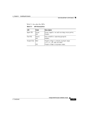
Fan assembly is in proper range. 78-6134-03 Catalyst 8540 Chassis Installation Guide 2-13 Failure. Failure. Output voltage is operating properly. Output voltage is on and receiving source power. Table 2-1 LED Descriptions LED Input OK Fan OK Output Fail State Green Off Green Off Red Off Description Power supply is outside of proper range, +3.3, +5, +12, and +42 VDC. Chapter 2 Installing the Chassis Connecting Power to the Chassis Table 2-1 describes the LEDs.
Fan assembly is in proper range. 78-6134-03 Catalyst 8540 Chassis Installation Guide 2-13 Failure. Failure. Output voltage is operating properly. Output voltage is on and receiving source power. Table 2-1 LED Descriptions LED Input OK Fan OK Output Fail State Green Off Green Off Red Off Description Power supply is outside of proper range, +3.3, +5, +12, and +42 VDC. Chapter 2 Installing the Chassis Connecting Power to the Chassis Table 2-1 describes the LEDs.
User Guide
Page 39
...and Interface Module Installation Guide for detailed information about the maintenance of the Catalyst 8540 CSR route processors and interface modules. Your chassis is configured as power supplies and system fan assemblies for the chassis. As your network requirements change the... detailed information about the maintenance of the Catalyst 8540 MSR route processors, port adapters, and interface modules. 78-6134-03 Catalyst 8540 Chassis Installation Guide 3-1 This chapter contains the following sections: • Replacing Power Supplies • Replacing the Fan Assembly Warning ...
...and Interface Module Installation Guide for detailed information about the maintenance of the Catalyst 8540 CSR route processors and interface modules. Your chassis is configured as power supplies and system fan assemblies for the chassis. As your network requirements change the... detailed information about the maintenance of the Catalyst 8540 MSR route processors, port adapters, and interface modules. 78-6134-03 Catalyst 8540 Chassis Installation Guide 3-1 This chapter contains the following sections: • Replacing Power Supplies • Replacing the Fan Assembly Warning ...

User Guide
Page 40
.... In systems with dual power supplies, connect each AC power supply to full power and maintain uninterrupted system operation. Make the attachment of the chassis. The grounded chassis M4 pemnuts require M4 bolts and locking hardware, which are installed, you need the following tools: • A 1/4-inch flat-blade screwdriver • A power supply bay cover Catalyst 8540 Chassis Installation Guide...
.... In systems with dual power supplies, connect each AC power supply to full power and maintain uninterrupted system operation. Make the attachment of the chassis. The grounded chassis M4 pemnuts require M4 bolts and locking hardware, which are installed, you need the following tools: • A 1/4-inch flat-blade screwdriver • A power supply bay cover Catalyst 8540 Chassis Installation Guide...
User Guide
Page 41
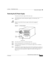
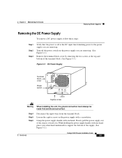
... to turn off the AC power supply could result in equipment damage. Figure 3-1 AC Power Supply Power cord connection 33014 Power switch INPUT OK FAN OUTPUT OK FAIL Step 2 Step 3 Step 4 Step 5 Captive screw Disconnect the AC power cord from the power cord connection. Slowly pull the power supply out of the supply. (See Figure 3-2.) 78-6134-03 Catalyst 8540 Chassis Installation Guide 3-3 Loosen...
... to turn off the AC power supply could result in equipment damage. Figure 3-1 AC Power Supply Power cord connection 33014 Power switch INPUT OK FAN OUTPUT OK FAIL Step 2 Step 3 Step 4 Step 5 Captive screw Disconnect the AC power cord from the power cord connection. Slowly pull the power supply out of the supply. (See Figure 3-2.) 78-6134-03 Catalyst 8540 Chassis Installation Guide 3-3 Loosen...

User Guide
Page 42
Install a power supply cover plate over the power supply bay opening and secure it aside. Catalyst 8540 Chassis Installation Guide 3-4 78-6134-03 Figure 3-2 Removing a Power Supply 33016 INPUT OK FAN OUTPUT OK FAIL INPUT OK FAN OUTPUT OK FAIL Step 6 Step 7 Pull the power supply out of the power supply bays. To install the AC power supply, see the "Installing Power Supplies" section on the power backplane...
Install a power supply cover plate over the power supply bay opening and secure it aside. Catalyst 8540 Chassis Installation Guide 3-4 78-6134-03 Figure 3-2 Removing a Power Supply 33016 INPUT OK FAN OUTPUT OK FAIL INPUT OK FAN OUTPUT OK FAIL Step 6 Step 7 Pull the power supply out of the power supply bays. To install the AC power supply, see the "Installing Power Supplies" section on the power backplane...
User Guide
Page 43
... the power supply you are removing. Slowly pull the power supply out of the supply. (See Figure 3-2.) 78-6134-03 Catalyst 8540 Chassis Installation Guide 3-5 Turn off to the DC input line furnishing power to ...power supply handle with one hand. Grasp the power supply handle with one hand, place your other hand underneath to the power supply you . Chapter 3 Maintaining the Chassis Replacing Power Supplies Removing the DC Power Supply To remove a DC power supply, follow these steps: Step 1 Step 2 Step 3 Verify that the power is off the power switch on the power supply...
... the power supply you are removing. Slowly pull the power supply out of the supply. (See Figure 3-2.) 78-6134-03 Catalyst 8540 Chassis Installation Guide 3-5 Turn off to the DC input line furnishing power to ...power supply handle with one hand. Grasp the power supply handle with one hand, place your other hand underneath to the power supply you . Chapter 3 Maintaining the Chassis Replacing Power Supplies Removing the DC Power Supply To remove a DC power supply, follow these steps: Step 1 Step 2 Step 3 Verify that the power is off the power switch on the power supply...

User Guide
Page 44
...Catalyst 8540 Chassis Installation Guide 3-6 78-6134-03 Never operate the system if the fan assembly is ready for immediate installation. Replacing the Fan Assembly This section describes how to the back panel. Replacing the Fan Assembly Chapter 3 Maintaining the Chassis Step 7 Install a power supply... cover plate over the opening and secure it across the route processor, switch modules, and interface modules. This protects the inner chassis from dust and prevents accidental...
...Catalyst 8540 Chassis Installation Guide 3-6 78-6134-03 Never operate the system if the fan assembly is ready for immediate installation. Replacing the Fan Assembly This section describes how to the back panel. Replacing the Fan Assembly Chapter 3 Maintaining the Chassis Step 7 Install a power supply... cover plate over the opening and secure it across the route processor, switch modules, and interface modules. This protects the inner chassis from dust and prevents accidental...


