User Guide
Page 7
1 C H A P T E R Preface vii Audience vii New and Changed Information vii Organization viii Conventions viii Related Documentation xi Obtaining Documentation xiii World Wide Web xiii Documentation CD-ROM xiii Ordering Documentation xiv Obtaining Technical Assistance xiv Cisco Connection Online xiv Technical Assistance Center xv Documentation Feedback xvi Product Overview 1-1 Interface Modules and Port Adapters 1-2 Route Processors 1-3 Switch Modules 1-3 Power Supplies 1-4 Fan Assembly 1-5 CONTENTS 78-6134-03 Catalyst 8540 Chassis Installation Guide v
1 C H A P T E R Preface vii Audience vii New and Changed Information vii Organization viii Conventions viii Related Documentation xi Obtaining Documentation xiii World Wide Web xiii Documentation CD-ROM xiii Ordering Documentation xiv Obtaining Technical Assistance xiv Cisco Connection Online xiv Technical Assistance Center xv Documentation Feedback xvi Product Overview 1-1 Interface Modules and Port Adapters 1-2 Route Processors 1-3 Switch Modules 1-3 Power Supplies 1-4 Fan Assembly 1-5 CONTENTS 78-6134-03 Catalyst 8540 Chassis Installation Guide v

User Guide
Page 9
... over if the primary route processor or primary switch module fails. New and Changed Information Feature Redundancy Description The Catalyst 8540 chassis supports fault tolerance by allowing a secondary (or redundant) route processor and switch module to be familiar with electronic circuitry and wiring ..., organization, and conventions of new information in the "Route Processors" section on page 1-3 and the "Switch Modules" section on page 1-3. 78-6134-03 Catalyst 8540 Chassis Installation Guide vii Chapter or Section Chapter 1, "Product Overview," in the document and how to obtain...
... over if the primary route processor or primary switch module fails. New and Changed Information Feature Redundancy Description The Catalyst 8540 chassis supports fault tolerance by allowing a secondary (or redundant) route processor and switch module to be familiar with electronic circuitry and wiring ..., organization, and conventions of new information in the "Route Processors" section on page 1-3 and the "Switch Modules" section on page 1-3. 78-6134-03 Catalyst 8540 Chassis Installation Guide vii Chapter or Section Chapter 1, "Product Overview," in the document and how to obtain...
User Guide
Page 14
Related Documentation Preface • Cisco Interactive Quick Start Guides: Catalyst 8540 http://www.cisco.com/mm/quickstart/ • Catalyst 8540 CSR Route Processor and Interface Module Installation Guide • Layer 3 Switching Software Feature and Configuration Guide Catalyst 8540 Chassis Installation Guide xii 78-6134-03
Related Documentation Preface • Cisco Interactive Quick Start Guides: Catalyst 8540 http://www.cisco.com/mm/quickstart/ • Catalyst 8540 CSR Route Processor and Interface Module Installation Guide • Layer 3 Switching Software Feature and Configuration Guide Catalyst 8540 Chassis Installation Guide xii 78-6134-03
User Guide
Page 15
... • Catalyst 8540 Hardware Quick Reference • Cisco Interactive Quick Start Guides: Catalyst 8540 http://www.cisco.com/mm/quickstart/ • Processor Installation Guide • ATM Port Adapter and Interface Module Installation Guide • Guide to ATM Technology • ATM Switch Router Quick Software Configuration Guide • ATM Switch Router Software Configuration Guide • ATM Switch Router Command Reference • ATM Switch Router Troubleshooting Guide...
... • Catalyst 8540 Hardware Quick Reference • Cisco Interactive Quick Start Guides: Catalyst 8540 http://www.cisco.com/mm/quickstart/ • Processor Installation Guide • ATM Port Adapter and Interface Module Installation Guide • Guide to ATM Technology • ATM Switch Router Quick Software Configuration Guide • ATM Switch Router Software Configuration Guide • ATM Switch Router Command Reference • ATM Switch Router Troubleshooting Guide...
User Guide
Page 19
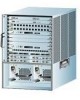
... hardware components and installation. CH A P T E R 1 Product Overview This chapter describes the Catalyst 8540, a 13-slot, modular chassis, and provides an overview of a fully populated Catalyst 8540 chassis. The following sections describe the chassis components: • Interface Modules and Port Adapters • Route Processors • Switch Modules • Power Supplies • Fan Assembly The chassis ships populated specifically to...
... hardware components and installation. CH A P T E R 1 Product Overview This chapter describes the Catalyst 8540, a 13-slot, modular chassis, and provides an overview of a fully populated Catalyst 8540 chassis. The following sections describe the chassis components: • Interface Modules and Port Adapters • Route Processors • Switch Modules • Power Supplies • Fan Assembly The chassis ships populated specifically to...

User Guide
Page 20
... 16 half-width port adapters in slots 0 through 3 and slots 9 through 12 of the chassis. Interface Modules and Port Adapters Figure 1-1 Catalyst 8540 Chassis Slots 0-3: Interface modules Slot 4: Route processor Slots 5-7: Switch modules Slot 8: Redundant route processor Slots 9-12: Interface modules Chapter 1 Product Overview 32600 INPUT FAN OUTPUT OK OK FAIL INPUT FAN OK OK Power supply...
... 16 half-width port adapters in slots 0 through 3 and slots 9 through 12 of the chassis. Interface Modules and Port Adapters Figure 1-1 Catalyst 8540 Chassis Slots 0-3: Interface modules Slot 4: Route processor Slots 5-7: Switch modules Slot 8: Redundant route processor Slots 9-12: Interface modules Chapter 1 Product Overview 32600 INPUT FAN OUTPUT OK OK FAIL INPUT FAN OK OK Power supply...
User Guide
Page 21
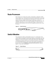
... to two route processors in the event that control the chassis. Figure 1-3 Switch Module STATUS ASCTATNIVDEBY SWITCH PROCESSOR 32602 78-6134-03 Catalyst 8540 Chassis Installation Guide 1-3 Two switch modules are primary and switch module 6 runs in standby mode. Figure 1-3 shows the switch module. To force the standby switch module to take over if the primary route processor fails. You can install up...
... to two route processors in the event that control the chassis. Figure 1-3 Switch Module STATUS ASCTATNIVDEBY SWITCH PROCESSOR 32602 78-6134-03 Catalyst 8540 Chassis Installation Guide 1-3 Two switch modules are primary and switch module 6 runs in standby mode. Figure 1-3 shows the switch module. To force the standby switch module to take over if the primary route processor fails. You can install up...
User Guide
Page 22
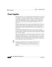
... alarm, to monitor the system. The processor monitors the temperature inside the module compartment, and the power supplies use two levels of the monitored parameters exceed... power supply temperature or voltage reaches the alarm level, the Output Fail LED may turn the power switch on page A-1. If the power supply shuts down again, remove and replace it detects a critical... It is a 13-slot, modular chassis with optional dual, fault-tolerant, load-sharing AC or DC power supplies. Power Supplies Chapter 1 Product Overview Power Supplies The Catalyst 8540 is either within the power supply...
... alarm, to monitor the system. The processor monitors the temperature inside the module compartment, and the power supplies use two levels of the monitored parameters exceed... power supply temperature or voltage reaches the alarm level, the Output Fail LED may turn the power switch on page A-1. If the power supply shuts down again, remove and replace it detects a critical... It is a 13-slot, modular chassis with optional dual, fault-tolerant, load-sharing AC or DC power supplies. Power Supplies Chapter 1 Product Overview Power Supplies The Catalyst 8540 is either within the power supply...
User Guide
Page 26
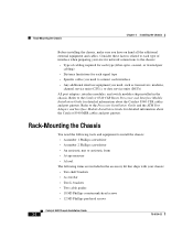
...the Catalyst 8540 CSR cables and port pinouts. Rack-Mounting the Chassis Chapter 2 Installing the Chassis Before installing the chassis, make sure you need, such as transceivers, modems, channel service units (CSUs), or data service units (DSUs) All port adapters, interface modules, and switch modules ship... • An antistatic mat or antistatic foam • A tape measure • A level The following tools and equipment to the Catalyst 8540 CSR Route Processor and Interface Module Installation Guide for detailed information about the Catalyst 8540 MSR cables and port pinouts.
...the Catalyst 8540 CSR cables and port pinouts. Rack-Mounting the Chassis Chapter 2 Installing the Chassis Before installing the chassis, make sure you need, such as transceivers, modems, channel service units (CSUs), or data service units (DSUs) All port adapters, interface modules, and switch modules ship... • An antistatic mat or antistatic foam • A tape measure • A level The following tools and equipment to the Catalyst 8540 CSR Route Processor and Interface Module Installation Guide for detailed information about the Catalyst 8540 MSR cables and port pinouts.

User Guide
Page 30
... bracket with the mounting holes in the mounting post. Use a tape measure and level to ensure that the chassis is straight and level. e. Catalyst 8540 Chassis Installation Guide 2-6 78-6134-03 f. d. Install the ten (five per side) 12-24 or 10-32 screws through the elongated holes ...in the L bracket and into the threaded holes in the equipment rack. Place the chassis on all modules. Check the release levers to ensure that all modules are installed securely and tighten any loose captive installation screws on the shelf brackets. Rack-Mounting the Chassis ...
... bracket with the mounting holes in the mounting post. Use a tape measure and level to ensure that the chassis is straight and level. e. Catalyst 8540 Chassis Installation Guide 2-6 78-6134-03 f. d. Install the ten (five per side) 12-24 or 10-32 screws through the elongated holes ...in the L bracket and into the threaded holes in the equipment rack. Place the chassis on all modules. Check the release levers to ensure that all modules are installed securely and tighten any loose captive installation screws on the shelf brackets. Rack-Mounting the Chassis ...
User Guide
Page 39
... Installation Guide and the ATM Port Adapter and Interface Module Installation Guide for detailed information about the maintenance of the Catalyst 8540 MSR route processors, port adapters, and interface modules. 78-6134-03 Catalyst 8540 Chassis Installation Guide 3-1 This chapter contains the following... the Site Preparation and Safety Guide. Note Refer to the Catalyst 8540 CSR Route Processor and Interface Module Installation Guide for detailed information about the maintenance of the Catalyst 8540 CSR route processors and interface modules. CH A P T E R 3 Maintaining the Chassis ...
... Installation Guide and the ATM Port Adapter and Interface Module Installation Guide for detailed information about the maintenance of the Catalyst 8540 MSR route processors, port adapters, and interface modules. 78-6134-03 Catalyst 8540 Chassis Installation Guide 3-1 This chapter contains the following... the Site Preparation and Safety Guide. Note Refer to the Catalyst 8540 CSR Route Processor and Interface Module Installation Guide for detailed information about the maintenance of the Catalyst 8540 CSR route processors and interface modules. CH A P T E R 3 Maintaining the Chassis ...

User Guide
Page 44
...Install a power supply cover plate over the opening and secure it across the route processor, switch modules, and interface modules. The absence of cooling air can cause an overtemperature condition. Catalyst 8540 Chassis Installation Guide 3-6 78-6134-03 Replacing the Fan Assembly This section describes how to replace...Installing Power Supplies" section on the left side of the chassis to heat up and can cause the interior of the chassis module cage. (See Figure 3-4.) The two captive installation screws secure the fan assembly to remain empty. Caution If you are replacing...
...Install a power supply cover plate over the opening and secure it across the route processor, switch modules, and interface modules. The absence of cooling air can cause an overtemperature condition. Catalyst 8540 Chassis Installation Guide 3-6 78-6134-03 Replacing the Fan Assembly This section describes how to replace...Installing Power Supplies" section on the left side of the chassis to heat up and can cause the interior of the chassis module cage. (See Figure 3-4.) The two captive installation screws secure the fan assembly to remain empty. Caution If you are replacing...

User Guide
Page 46
Catalyst 8540 Chassis Installation Guide 3-8 78-6134-03 Do not attempt to reinstall a fan assembly immediately if the power has not been turned off. Caution Never operate ... Assembly To remove the existing chassis fan assembly, follow these steps: Step 1 Step 2 Step 3 Step 4 Locate the fan assembly on the left side of the module cage, above the power supply. (See Figure 3-4.) Use a flat-blade screwdriver to loosen each of the chassis and put it frees the backplane. An overtemperature...
Catalyst 8540 Chassis Installation Guide 3-8 78-6134-03 Do not attempt to reinstall a fan assembly immediately if the power has not been turned off. Caution Never operate ... Assembly To remove the existing chassis fan assembly, follow these steps: Step 1 Step 2 Step 3 Step 4 Locate the fan assembly on the left side of the module cage, above the power supply. (See Figure 3-4.) Use a flat-blade screwdriver to loosen each of the chassis and put it frees the backplane. An overtemperature...
User Guide
Page 49
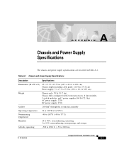
... power supply specifications are described in . (20.1 x 18.1 x 38.9 cm) Weight Airflow Chassis only: 70 lb (31.7 kg) Chassis fully configured with 2 route processors, 8 line modules, 3 switch modules, and 2 power supplies:160 lb (72.5 kg) AC power supply: 22 lb DC power supply: 25 lb 200 lfm1 through the system fan assembly Operating...° C) Humidity 10 to 90%, noncondensing, operating 5 to 95%, noncondensing, nonoperating, and storage Altitude, operating -500 to 6562 ft. (-52 to 2000 m) 78-6134-03 Catalyst 8540 Chassis Installation Guide A-1
... power supply specifications are described in . (20.1 x 18.1 x 38.9 cm) Weight Airflow Chassis only: 70 lb (31.7 kg) Chassis fully configured with 2 route processors, 8 line modules, 3 switch modules, and 2 power supplies:160 lb (72.5 kg) AC power supply: 22 lb DC power supply: 25 lb 200 lfm1 through the system fan assembly Operating...° C) Humidity 10 to 90%, noncondensing, operating 5 to 95%, noncondensing, nonoperating, and storage Altitude, operating -500 to 6562 ft. (-52 to 2000 m) 78-6134-03 Catalyst 8540 Chassis Installation Guide A-1
User Guide
Page 60
... xi feedback xvi MSR xiii obtaining xiii ordering xiv organization viii related xi software configuration xi www xiii E electromagnetic interference. See EMI EMI compliance A-2, A-3 specifications A-2 Catalyst 8540 Chassis Installation Guide 2 environmental monitoring chassis 1-4 using 1-5 ESD disposable strap 2-3 grounding strap 2-3 F fan assembly airflow 1-5 description 1-5 failure 1-5 LEDs 3-9 removing 3-8 replacing 3-6 I installing AC power supply 3-2 chassis...
... xi feedback xvi MSR xiii obtaining xiii ordering xiv organization viii related xi software configuration xi www xiii E electromagnetic interference. See EMI EMI compliance A-2, A-3 specifications A-2 Catalyst 8540 Chassis Installation Guide 2 environmental monitoring chassis 1-4 using 1-5 ESD disposable strap 2-3 grounding strap 2-3 F fan assembly airflow 1-5 description 1-5 failure 1-5 LEDs 3-9 removing 3-8 replacing 3-6 I installing AC power supply 3-2 chassis...

User Guide
Page 61
... 1-4 removing 2-7 shutdown (note) 1-4 temperature 1-4 voltage monitoring 1-5 See also AC power See also DC power R rack-mounting equipment 2-2 procedures 2-2 tools 2-2 redundancy description 1-3 power supplies 1-4 route processor 1-3 switch modules 1-3 Catalyst 8540 Chassis Installation Guide 3
... 1-4 removing 2-7 shutdown (note) 1-4 temperature 1-4 voltage monitoring 1-5 See also AC power See also DC power R rack-mounting equipment 2-2 procedures 2-2 tools 2-2 redundancy description 1-3 power supplies 1-4 route processor 1-3 switch modules 1-3 Catalyst 8540 Chassis Installation Guide 3
User Guide
Page 62
... 3-6 power supplies 2-7 route processors description 1-3 redundancy 1-3 related documentation 1-1 slots 1-3 S safety preinstall 2-1, 3-1 warnings B-1 site environment layout 2-1 preparing 2-1 specifications AC power supply A-2 airflow A-1 chassis A-1 DC power supply A-3 switch modules description 1-3 redundancy 1-3 related documentation 1-1 Catalyst 8540 Chassis Installation Guide 4 slots 1-3 T TAC contacts xv description xiv, xv obtaining xiv, xv Technical Assistance Center.
... 3-6 power supplies 2-7 route processors description 1-3 redundancy 1-3 related documentation 1-1 slots 1-3 S safety preinstall 2-1, 3-1 warnings B-1 site environment layout 2-1 preparing 2-1 specifications AC power supply A-2 airflow A-1 chassis A-1 DC power supply A-3 switch modules description 1-3 redundancy 1-3 related documentation 1-1 Catalyst 8540 Chassis Installation Guide 4 slots 1-3 T TAC contacts xv description xiv, xv obtaining xiv, xv Technical Assistance Center.


