
Configuration Guide
Page 4
... 1-44 AC-Input and DC-Input Power Supply Overview 1-46 Arbiter Overview 1-50 Chassis Interface Overview 1-50 Fan Tray and Blower Assembly Overview 1-51 Cisco 7505 Fan Tray Assembly 1-52 Cisco 7507 and Cisco 7507-MX Blower Assembly 1-52 Cisco 7513, Cisco 7513-MX, and Cisco 7576 Blower Module Assembly 1-53 Interface Processor Overview 1-54 System Software Overview...
... 1-44 AC-Input and DC-Input Power Supply Overview 1-46 Arbiter Overview 1-50 Chassis Interface Overview 1-50 Fan Tray and Blower Assembly Overview 1-51 Cisco 7505 Fan Tray Assembly 1-52 Cisco 7507 and Cisco 7507-MX Blower Assembly 1-52 Cisco 7513, Cisco 7513-MX, and Cisco 7576 Blower Module Assembly 1-53 Interface Processor Overview 1-54 System Software Overview...

Configuration Guide
Page 5
... Considerations 3-1 Providing a Ground Connection for the Chassis 3-2 Installing the Cisco 7505 3-4 Cisco 7505 Installation Considerations 3-7 Rack-Mounting the Cisco 7505 3-7 Attaching the Cisco 7505 Cable-Management Brackets 3-9 Connecting Power to the Cisco 7505 DC-Input Power Supply 3-9 Installing the Cisco 7507 and Cisco 7507-MX 3-11 Cisco 7507 and Cisco 7507-MX Installation Considerations 3-14 Installing Cisco 7507 and Cisco 7507-MX Power Supplies 3-14 Connecting Power...
... Considerations 3-1 Providing a Ground Connection for the Chassis 3-2 Installing the Cisco 7505 3-4 Cisco 7505 Installation Considerations 3-7 Rack-Mounting the Cisco 7505 3-7 Attaching the Cisco 7505 Cable-Management Brackets 3-9 Connecting Power to the Cisco 7505 DC-Input Power Supply 3-9 Installing the Cisco 7507 and Cisco 7507-MX 3-11 Cisco 7507 and Cisco 7507-MX Installation Considerations 3-14 Installing Cisco 7507 and Cisco 7507-MX Power Supplies 3-14 Connecting Power...

Configuration Guide
Page 7
... the Cisco 7505 5-2 Maintenance Procedures for the Cisco 7505 5-3 Removing and Replacing the Cisco 7505 Cover Panel 5-3 Removing and Replacing the Cisco 7505 Fan Tray 5-5 Removing and Replacing the Cisco 7505 Power Harness Cover 5-7 Removing and Replacing the Cisco 7505 Backplane Cover 5-9 Removing and Replacing the Chassis Interface in the Cisco 7505 5-11 Removing and Replacing the Cisco 7505 Power Supply 5-13 Maintaining Your Cisco 7507 and Cisco 7507...
... the Cisco 7505 5-2 Maintenance Procedures for the Cisco 7505 5-3 Removing and Replacing the Cisco 7505 Cover Panel 5-3 Removing and Replacing the Cisco 7505 Fan Tray 5-5 Removing and Replacing the Cisco 7505 Power Harness Cover 5-7 Removing and Replacing the Cisco 7505 Backplane Cover 5-9 Removing and Replacing the Chassis Interface in the Cisco 7505 5-11 Removing and Replacing the Cisco 7505 Power Supply 5-13 Maintaining Your Cisco 7507 and Cisco 7507...

Configuration Guide
Page 8
... Replacing the Chassis Interface in the Cisco 7513, Cisco 7513-MX, and Cisco 7576 7-14 Troubleshooting a Cisco 7500 Series Router 8-1 Troubleshooting Overview 8-2 Problem Solving with Cisco 7500 Series Subsystems 8-3 Troubleshooting Guidelines for the Cisco 7505 8-4 Identifying Cisco 7505 Startup Problems 8-4 Troubleshooting the Cisco 7505 Power Subsystem 8-7 Troubleshooting the Cisco 7505 Cooling Subsystem 8-7 Troubleshooting Guidelines for the Cisco 7507 and Cisco 7507-MX 8-8 Identifying Cisco 7507 and Cisco 7507...
... Replacing the Chassis Interface in the Cisco 7513, Cisco 7513-MX, and Cisco 7576 7-14 Troubleshooting a Cisco 7500 Series Router 8-1 Troubleshooting Overview 8-2 Problem Solving with Cisco 7500 Series Subsystems 8-3 Troubleshooting Guidelines for the Cisco 7505 8-4 Identifying Cisco 7505 Startup Problems 8-4 Troubleshooting the Cisco 7505 Power Subsystem 8-7 Troubleshooting the Cisco 7505 Cooling Subsystem 8-7 Troubleshooting Guidelines for the Cisco 7507 and Cisco 7507-MX 8-8 Identifying Cisco 7507 and Cisco 7507...

Configuration Guide
Page 23
...; Chassis Interface Overview, page 1-50 • Fan Tray and Blower Assembly Overview, page 1-51 • Interface Processor Overview, page 1-54 This section provides a general overview of interface processors; The remaining sections of this chapter describe the Cisco 7500 series routers, and include the following routers: Cisco 7505, Cisco 7507, Cisco 7507-MX, Cisco 7513, Cisco 7513-MX, and Cisco...
...; Chassis Interface Overview, page 1-50 • Fan Tray and Blower Assembly Overview, page 1-51 • Interface Processor Overview, page 1-54 This section provides a general overview of interface processors; The remaining sections of this chapter describe the Cisco 7500 series routers, and include the following routers: Cisco 7505, Cisco 7507, Cisco 7507-MX, Cisco 7513, Cisco 7513-MX, and Cisco...

Configuration Guide
Page 26
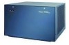
... 0 DC OK LED H2761 Power receptacle AC-input power supply Cisco 7505 CyBus Backplane The CyBus backplane in Figure 1-3. Cisco 7500 Series Installation and Configuration Guide 1-4 OL-5008-03 B0 The Cisco 7505 CyBus backplane has five slots: interface processor slots 0 through ...transfers information at up to 1.067 Gbps. Figure 1-2 Cisco 7505 (Rear View) Power switch Chassis grounding receptacles ENABLE NORMAL CPU HALT RESET AUX. Cisco 7505 Overview Figure 1-1 Cisco 7505 (Front View) Captive fasteners Chapter 1 Cisco 7500 Series Product Overview H2009 Figure 1-2 shows details ...
... 0 DC OK LED H2761 Power receptacle AC-input power supply Cisco 7505 CyBus Backplane The CyBus backplane in Figure 1-3. Cisco 7500 Series Installation and Configuration Guide 1-4 OL-5008-03 B0 The Cisco 7505 CyBus backplane has five slots: interface processor slots 0 through ...transfers information at up to 1.067 Gbps. Figure 1-2 Cisco 7505 (Rear View) Power switch Chassis grounding receptacles ENABLE NORMAL CPU HALT RESET AUX. Cisco 7505 Overview Figure 1-1 Cisco 7505 (Front View) Captive fasteners Chapter 1 Cisco 7500 Series Product Overview H2009 Figure 1-2 shows details ...
Configuration Guide
Page 27
... you are installing it in the RSP slot. Chapter 1 Cisco 7500 Series Product Overview Cisco 7505 Overview Figure 1-3 CyBus Backplane in the Cisco 7505 SLOT 4 SLOT 3 SLOT 2 SLOT 1 SLOT 0 H2875 The backplane slots are keyed so that you can be installed only in . (48.26 cm) Chassis only (including power supply and fan array): 46 lb...
... you are installing it in the RSP slot. Chapter 1 Cisco 7500 Series Product Overview Cisco 7505 Overview Figure 1-3 CyBus Backplane in the Cisco 7505 SLOT 4 SLOT 3 SLOT 2 SLOT 1 SLOT 0 H2875 The backplane slots are keyed so that you can be installed only in . (48.26 cm) Chassis only (including power supply and fan array): 46 lb...

Configuration Guide
Page 28
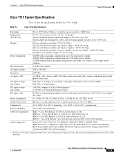
The chassis will operate with a wide variety of protocols and any combination of available electrical interfaces and media. Although a second power supply is not a supported configuration and should not be attempted. Cisco 7500 Series Installation and Configuration Guide 1-6 OL-5008-03 B0 Cisco 7507 Overview Chapter 1 Cisco 7500 Series Product Overview Table 1-1 Cisco 7505 Specifications (continued) Description...
The chassis will operate with a wide variety of protocols and any combination of available electrical interfaces and media. Although a second power supply is not a supported configuration and should not be attempted. Cisco 7500 Series Installation and Configuration Guide 1-6 OL-5008-03 B0 Cisco 7507 Overview Chapter 1 Cisco 7500 Series Product Overview Table 1-1 Cisco 7505 Specifications (continued) Description...

Configuration Guide
Page 30
... Installation and Configuration Guide 1-8 OL-5008-03 B0 Figure 1-5 Cisco 7507 (Rear View) Captive installation screw Upper power supply Chassis grounding receptacles Captive installation screw Lower power supply DC AC FAIL POWER I O DC AC FAIL POWER I O ROUTE SWITCH PROCESSOR 2 NORMAL ENABLE EJECT SLOTS0LOT 1 SLAVME ASTER ...
... Installation and Configuration Guide 1-8 OL-5008-03 B0 Figure 1-5 Cisco 7507 (Rear View) Captive installation screw Upper power supply Chassis grounding receptacles Captive installation screw Lower power supply DC AC FAIL POWER I O DC AC FAIL POWER I O ROUTE SWITCH PROCESSOR 2 NORMAL ENABLE EJECT SLOTS0LOT 1 SLAVME ASTER ...

Configuration Guide
Page 32
...cord is 28 in. (71.12 cm) Chassis only: 76 lb (34.47 kg) Chassis fully configured, using all slots and 2 power supplies: 145 lb (65.76 kg) 700W maximum (for the Cisco 7507 system. Cisco IOS Release 12.0(9)S or a later release of 10.3 RSP4/4+ - Cisco IOS Release 11.1(8)CA or a later release ...of 11.1 RSP8 - Cisco IOS Release 12.1(12)E and ...
...cord is 28 in. (71.12 cm) Chassis only: 76 lb (34.47 kg) Chassis fully configured, using all slots and 2 power supplies: 145 lb (65.76 kg) 700W maximum (for the Cisco 7507 system. Cisco IOS Release 12.0(9)S or a later release of 10.3 RSP4/4+ - Cisco IOS Release 11.1(8)CA or a later release ...of 11.1 RSP8 - Cisco IOS Release 12.1(12)E and ...

Configuration Guide
Page 33
... that provide a direct connection between the two CyBuses in the Cisco 7507-MX and your external networks. There are bays for access to two AC-input or DC-input power supplies. The chassis will operate with a wide variety of protocols and any combination ... and 1, Route Switch Processor (RSP2, RSP4/4+, RSP8, or RSP16) slots 2 and 3, and interface processor slots 4 through 6. Chapter 1 Cisco 7500 Series Product Overview Cisco 7507-MX Overview Cisco 7507-MX Overview The Cisco 7507-MX supports multiprotocol, multimedia routing and bridging with one for each interface processor slot.
... that provide a direct connection between the two CyBuses in the Cisco 7507-MX and your external networks. There are bays for access to two AC-input or DC-input power supplies. The chassis will operate with a wide variety of protocols and any combination ... and 1, Route Switch Processor (RSP2, RSP4/4+, RSP8, or RSP16) slots 2 and 3, and interface processor slots 4 through 6. Chapter 1 Cisco 7500 Series Product Overview Cisco 7507-MX Overview Cisco 7507-MX Overview The Cisco 7507-MX supports multiprotocol, multimedia routing and bridging with one for each interface processor slot.

Configuration Guide
Page 34
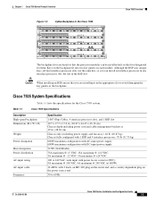
Figure 1-8 Cisco 7507-MX (Rear View) Captive installation screw Upper power supply Chassis grounding receptacles Captive installation screw Lower power supply DC AC FAIL POWER I O DC AC FAIL POWER I O ROUTE SWITCH PROCESSOR 2 NORMAL ENABLE EJECT ... slots 0 and 1 (CyBus 0), RSP slots 2 and 3, and interface processor slots 4 through 6 (CyBus 1), as shown in Figure 1-9. 1-12 Cisco 7500 Series Installation and Configuration Guide OL-5008-03 B0 Cisco 7507-MX Overview Chapter 1 Cisco 7500 Series Product Overview Figure 1-8 shows details on the rear, interface-processor end of the...
Figure 1-8 Cisco 7507-MX (Rear View) Captive installation screw Upper power supply Chassis grounding receptacles Captive installation screw Lower power supply DC AC FAIL POWER I O DC AC FAIL POWER I O ROUTE SWITCH PROCESSOR 2 NORMAL ENABLE EJECT ... slots 0 and 1 (CyBus 0), RSP slots 2 and 3, and interface processor slots 4 through 6 (CyBus 1), as shown in Figure 1-9. 1-12 Cisco 7500 Series Installation and Configuration Guide OL-5008-03 B0 Cisco 7507-MX Overview Chapter 1 Cisco 7500 Series Product Overview Figure 1-8 shows details on the rear, interface-processor end of the...

Configuration Guide
Page 36
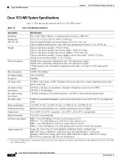
... the router end, and a country-dependent plug on the power source end 50 to 60 Hz autoranging 10A maximum @ 100 VAC, 6A maximum @ 240 VAC, chassis fully configured -40 VDC minimum, -48 VDC nominal, -72 VDC maximum +5.2 VDC @ 95A, +12 VDC @ 15A, -12 VDC @ 5A, +24 VDC @ 4A ... 104°F (0 to 40°C) -4 to 149°F (-20 to 65°C) 10 to 90%, noncondensing RSP2 - Cisco IOS Release 12.0(9)S or a later release of 11.1 RSP8 - Table 1-3 Cisco 7507-MX Specifications Description High-speed backplane Dimensions (H x W x D) Weight Power supply Power dissipation Heat dissipation AC-input voltage ...
... the router end, and a country-dependent plug on the power source end 50 to 60 Hz autoranging 10A maximum @ 100 VAC, 6A maximum @ 240 VAC, chassis fully configured -40 VDC minimum, -48 VDC nominal, -72 VDC maximum +5.2 VDC @ 95A, +12 VDC @ 15A, -12 VDC @ 5A, +24 VDC @ 4A ... 104°F (0 to 40°C) -4 to 149°F (-20 to 65°C) 10 to 90%, noncondensing RSP2 - Cisco IOS Release 12.0(9)S or a later release of 11.1 RSP8 - Table 1-3 Cisco 7507-MX Specifications Description High-speed backplane Dimensions (H x W x D) Weight Power supply Power dissipation Heat dissipation AC-input voltage ...

Configuration Guide
Page 37
.... Caution Because of available electrical interfaces and media. OL-5008-03 B0 Cisco 7500 Series Installation and Configuration Guide 1-15 Doing so might cause damage. The Cisco 7513 is not required, it allows load sharing and increased system availability. The chassis will operate with a wide variety of protocols and any combination of agency...
.... Caution Because of available electrical interfaces and media. OL-5008-03 B0 Cisco 7500 Series Installation and Configuration Guide 1-15 Doing so might cause damage. The Cisco 7513 is not required, it allows load sharing and increased system availability. The chassis will operate with a wide variety of protocols and any combination of agency...

Configuration Guide
Page 39
... for the RSPs and interface processors, and transfers information at the rear of the Cisco 7513. OL-5008-03 B0 Cisco 7500 Series Installation and Configuration Guide 1-17 Figure 1-11 Cisco 7513 (Rear View) Blower module Cable-management bracket Card cage and processor modules Air... intake vent Power supplies Chassis grounding receptacles AC OK FAN OK OUTPUT FAIL POWER A I 0 POWER B 122373 Cisco 7513 Dual CyBus Backplane The dual CyBus backplane, located at up to 2.134 Gbps (1.067 ...
... for the RSPs and interface processors, and transfers information at the rear of the Cisco 7513. OL-5008-03 B0 Cisco 7500 Series Installation and Configuration Guide 1-17 Figure 1-11 Cisco 7513 (Rear View) Blower module Cable-management bracket Card cage and processor modules Air... intake vent Power supplies Chassis grounding receptacles AC OK FAN OK OUTPUT FAIL POWER A I 0 POWER B 122373 Cisco 7513 Dual CyBus Backplane The dual CyBus backplane, located at up to 2.134 Gbps (1.067 ...
Configuration Guide
Page 41
... Series Installation and Configuration Guide 1-19 The Cisco 7513 requires a minimum of 12.0 S RSP16 - Table 1-4 Cisco 7513 Specifications Backplane Two 1.0677-Gbps CyBuses, 11 interface processor slots, 2 RSP slots Dimensions (H x W x D) 33.75 x 17.5 x 22 in. (85.73 x 44.45 x 55.88 cm) Chassis width including rack-mount flanges is 18.93 in. (48...
... Series Installation and Configuration Guide 1-19 The Cisco 7513 requires a minimum of 12.0 S RSP16 - Table 1-4 Cisco 7513 Specifications Backplane Two 1.0677-Gbps CyBuses, 11 interface processor slots, 2 RSP slots Dimensions (H x W x D) 33.75 x 17.5 x 22 in. (85.73 x 44.45 x 55.88 cm) Chassis width including rack-mount flanges is 18.93 in. (48...

Configuration Guide
Page 42
... electrical interfaces and media. The chassis will operate with a wide variety of protocols and any combination of agency compliance and safety issues, mixing AC-input and DC-input power supplies in the Cisco 7513-MX and your external networks. The Cisco 7513-MX supports 11 VIPs, one... power supply is shown in Figure 1-13. There are bays for each interface processor slot. Cisco 7513-MX Overview Chapter 1 Cisco 7500 Series Product Overview Cisco 7513-MX Overview The Cisco 7513-MX router supports multiprotocol, multimedia routing and bridging with one for up to two AC-input...
... electrical interfaces and media. The chassis will operate with a wide variety of protocols and any combination of agency compliance and safety issues, mixing AC-input and DC-input power supplies in the Cisco 7513-MX and your external networks. The Cisco 7513-MX supports 11 VIPs, one... power supply is shown in Figure 1-13. There are bays for each interface processor slot. Cisco 7513-MX Overview Chapter 1 Cisco 7500 Series Product Overview Cisco 7513-MX Overview The Cisco 7513-MX router supports multiprotocol, multimedia routing and bridging with one for up to two AC-input...

Configuration Guide
Page 44
... slots (slots 6 and 7); Figure 1-14 Cisco 7513-MX (Rear View) Blower module Cable-management bracket Card cage and processor modules Air intake vent Power supplies Chassis grounding receptacles AC OK FAN OK OUTPUT FAIL POWER A I 0 POWER B 122374 Cisco 7513-MX Dual CyBus Backplane The dual CyBus... backplane, located at the rear of the Cisco 7513-MX. Cisco 7513-MX Overview Chapter 1 Cisco 7500 Series Product Overview...
... slots (slots 6 and 7); Figure 1-14 Cisco 7513-MX (Rear View) Blower module Cable-management bracket Card cage and processor modules Air intake vent Power supplies Chassis grounding receptacles AC OK FAN OK OUTPUT FAIL POWER A I 0 POWER B 122374 Cisco 7513-MX Dual CyBus Backplane The dual CyBus... backplane, located at the rear of the Cisco 7513-MX. Cisco 7513-MX Overview Chapter 1 Cisco 7500 Series Product Overview...
Configuration Guide
Page 46
... flanges is 18.93 in. (48.1 cm) Chassis depth including power cables and cable-management bracket is 24 in the European Union) DC-input cable 8 AWG (recommended minimum), with a 20A receptacle at the power source. Cisco IOS Release 10.3(6) or a later release of 11.1 RSP8 - Cisco IOS Release 12.0(9)S or a later release of...
... flanges is 18.93 in. (48.1 cm) Chassis depth including power cables and cable-management bracket is 24 in the European Union) DC-input cable 8 AWG (recommended minimum), with a 20A receptacle at the power source. Cisco IOS Release 10.3(6) or a later release of 11.1 RSP8 - Cisco IOS Release 12.0(9)S or a later release of...

Configuration Guide
Page 47
...Cisco 7513 and Cisco 7576 Chassis Replacement and Upgrade Instructions. OL-5008-03 B0 Cisco 7500 Series Installation and Configuration Guide 1-25 The Cisco 7576 consists of the Cisco 7576. These routers are bays for each interface processor slot; 6 VIPs are supported in slot 7. The Cisco...and two RSP4/4+s. The Cisco 7576 upgrade kit includes only the system chassis, which includes the card cage and backplane. Caution Because of the Cisco 7576 has 13 slots. Although a second power supply is housed within the chassis footprint of available electrical interfaces...
...Cisco 7513 and Cisco 7576 Chassis Replacement and Upgrade Instructions. OL-5008-03 B0 Cisco 7500 Series Installation and Configuration Guide 1-25 The Cisco 7576 consists of the Cisco 7576. These routers are bays for each interface processor slot; 6 VIPs are supported in slot 7. The Cisco...and two RSP4/4+s. The Cisco 7576 upgrade kit includes only the system chassis, which includes the card cage and backplane. Caution Because of the Cisco 7576 has 13 slots. Although a second power supply is housed within the chassis footprint of available electrical interfaces...
