
Quick Start Guide
Page 2
... coincidental. Any Internet Protocol (IP) addresses and phone numbers used in the document are trademarks; Any examples, command display output, network topology diagrams, and other countries. Copyright © 1981, Regents of the University of Cisco Systems, Inc. CCDE, CCENT, CCSI, Cisco Eos, Cisco Explorer, Cisco HealthPresence, Cisco IronPort, the Cisco logo, Cisco Nurse Connect, Cisco Pulse, Cisco SensorBase, Cisco StackPower, Cisco StadiumVision, Cisco TelePresence, Cisco TrustSec, Cisco Unified Computing System, Cisco WebEx, DCE, Flip Channels, Flip for...
... coincidental. Any Internet Protocol (IP) addresses and phone numbers used in the document are trademarks; Any examples, command display output, network topology diagrams, and other countries. Copyright © 1981, Regents of the University of Cisco Systems, Inc. CCDE, CCENT, CCSI, Cisco Eos, Cisco Explorer, Cisco HealthPresence, Cisco IronPort, the Cisco logo, Cisco Nurse Connect, Cisco Pulse, Cisco SensorBase, Cisco StackPower, Cisco StadiumVision, Cisco TelePresence, Cisco TrustSec, Cisco Unified Computing System, Cisco WebEx, DCE, Flip Channels, Flip for...
Quick Start Guide
Page 17
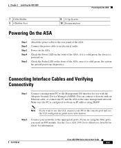
... IP address using the fiber ports, you want to use with an Ethernet cable, or connect the PC and the ASA to the same management network. Check the Power LED on . Connecting Interface Cables and Verifying Connectivity Step 1 Connect a management PC to the Management 0/0 interface for information. 78-19753-01 Cisco ASA 5500 Series Quick Start Guide 3-3 Check the Status LED on the ASA. Power on the front of the ASA. Connect the power cable to an electrical outlet. If you are using DHCP. See the Cisco ASA 5500 Series Hardware Installation Guide for use the CLI, connect...
... IP address using the fiber ports, you want to use with an Ethernet cable, or connect the PC and the ASA to the same management network. Check the Power LED on . Connecting Interface Cables and Verifying Connectivity Step 1 Connect a management PC to the Management 0/0 interface for information. 78-19753-01 Cisco ASA 5500 Series Quick Start Guide 3-3 Check the Status LED on the ASA. Power on the front of the ASA. Connect the power cable to an electrical outlet. If you are using DHCP. See the Cisco ASA 5500 Series Hardware Installation Guide for use the CLI, connect...
Quick Start Guide
Page 30
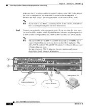
... the Cisco ASA 5585-X Adaptive Security Appliance Hardware Installation Guide for more information. 300016 1 2 SFP1 SFP0 7 6 5 4 3 2 1 0 1 MGMT 0 0 1 USB PWR BOOT ALARM ACT VPN PS1 PS0 HDD1 HDD0 AUX CONSOLE RESET SFP1 SFP0 7 6 5 4 3 2 1 0 1 MGMT 0 0 1 USB PWR BOOT ALARM ACT VPN PS1 PS0 HDD1 HDD0 AUX CONSOLE RESET 3 Management PC Unsecure Network Secure Network Cisco ASA 5580 Series Quick Start Guide 5-4 78-19753-01 If you are using DHCP. (By default, the ASA is configured to obtain an IP address using the fiber ports, you need an SFP+ module...
... the Cisco ASA 5585-X Adaptive Security Appliance Hardware Installation Guide for more information. 300016 1 2 SFP1 SFP0 7 6 5 4 3 2 1 0 1 MGMT 0 0 1 USB PWR BOOT ALARM ACT VPN PS1 PS0 HDD1 HDD0 AUX CONSOLE RESET SFP1 SFP0 7 6 5 4 3 2 1 0 1 MGMT 0 0 1 USB PWR BOOT ALARM ACT VPN PS1 PS0 HDD1 HDD0 AUX CONSOLE RESET 3 Management PC Unsecure Network Secure Network Cisco ASA 5580 Series Quick Start Guide 5-4 78-19753-01 If you are using DHCP. (By default, the ASA is configured to obtain an IP address using the fiber ports, you need an SFP+ module...
Getting Started Guide
Page 5
... Adaptive Security Appliance for a DMZ Deployment 8-8 Configuration Requirements 8-9 Information to Have Available 8-10 Enabling Inside Clients to Communicate with Devices on the Internet 8-10 Enabling Inside Clients to Communicate with the DMZ Web Server 8-10 Translating Internal Client IP Addresses Between the Inside and DMZ Interfaces 8-11 Translating the Public Address of the Web Server to its Real Address on the Inside Interface 8-14 Configuring Static PAT for Public Access to the DMZ Web Server (Port Forwarding) 8-17 Cisco ASA 5500 Series Getting Started Guide...
... Adaptive Security Appliance for a DMZ Deployment 8-8 Configuration Requirements 8-9 Information to Have Available 8-10 Enabling Inside Clients to Communicate with Devices on the Internet 8-10 Enabling Inside Clients to Communicate with the DMZ Web Server 8-10 Translating Internal Client IP Addresses Between the Inside and DMZ Interfaces 8-11 Translating the Public Address of the Web Server to its Real Address on the Inside Interface 8-14 Configuring Static PAT for Public Access to the DMZ Web Server (Port Forwarding) 8-17 Cisco ASA 5500 Series Getting Started Guide...

Getting Started Guide
Page 35
... fiber Ethernet ports. Chapter 3 Installing the ASA 5550 Connecting Interface Cables Table 3-4 LEDs on Bus G1 (continued) LED 3, 8 SPEED 4 POWER 5 STATUS Color State Off 10 MB Green 100 MB Amber 1000 MB (GigE) Green On Green Flashing Green Solid Amber Solid Description There is network activity at 1000 Mbps. This port is booting. Note You can also disable management-only mode on a flat, stable surface, or in the Cisco ASA 5500 Series Command...
... fiber Ethernet ports. Chapter 3 Installing the ASA 5550 Connecting Interface Cables Table 3-4 LEDs on Bus G1 (continued) LED 3, 8 SPEED 4 POWER 5 STATUS Color State Off 10 MB Green 100 MB Amber 1000 MB (GigE) Green On Green Flashing Green Solid Amber Solid Description There is network activity at 1000 Mbps. This port is booting. Note You can also disable management-only mode on a flat, stable surface, or in the Cisco ASA 5500 Series Command...

Getting Started Guide
Page 40
Figure 3-14 1 Removing the Fiber Port Plug 2 STATUS 143146 1 Port plug 2 SFP module b. Connecting Interface Cables Chapter 3 Installing the ASA 5550 Step 6 b. Connect the LC connector to a network device, such as shown in Figure 3-15. 3-18 Cisco ASA 5500 Series Getting Started Guide 78-19186-01 Note Slot 1 contains four copper Ethernet ports and four fiber Ethernet ports. Connect the other end of the Ethernet cable to the SFP module as a router, switch or hub. Install the SFP module: - For example, you...
Figure 3-14 1 Removing the Fiber Port Plug 2 STATUS 143146 1 Port plug 2 SFP module b. Connecting Interface Cables Chapter 3 Installing the ASA 5550 Step 6 b. Connect the LC connector to a network device, such as shown in Figure 3-15. 3-18 Cisco ASA 5500 Series Getting Started Guide 78-19186-01 Note Slot 1 contains four copper Ethernet ports and four fiber Ethernet ports. Connect the other end of the Ethernet cable to the SFP module as a router, switch or hub. Install the SFP module: - For example, you...

Getting Started Guide
Page 41
... other end of the cable to Do Next 1 LC connector 2 SFP module Step 7 Step 8 c. Chapter 3 Installing the ASA 5550 Figure 3-15 Connecting the LC Connector LNK 3 2 1 Cisco SSM-4GE 0 SPD 2 1 POWER STATUS 153214 MMGGMMTT UUSSBB22 USB1 What to a network device, such as a router, switch, or hub. Connect the other end to Do Next Continue with Chapter 7, "Configuring the Adaptive Security Appliance." 78-19186-01 Cisco ASA 5500 Series Getting Started Guide 3-19
... other end of the cable to Do Next 1 LC connector 2 SFP module Step 7 Step 8 c. Chapter 3 Installing the ASA 5550 Figure 3-15 Connecting the LC Connector LNK 3 2 1 Cisco SSM-4GE 0 SPD 2 1 POWER STATUS 153214 MMGGMMTT UUSSBB22 USB1 What to a network device, such as a router, switch, or hub. Connect the other end to Do Next Continue with Chapter 7, "Configuring the Adaptive Security Appliance." 78-19186-01 Cisco ASA 5500 Series Getting Started Guide 3-19
Getting Started Guide
Page 50
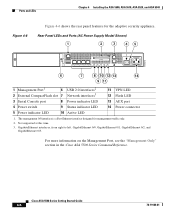
...interface designed for the adaptive security appliance. For more information on the Management Port, see the "Management-Only" section in the Cisco ASA 5500 Series Command Reference. Rear Panel LEDs and Ports (AC Power Supply Model Shown) 1 2 3 45 CONSOLE AUX MGMT USB2 USB1 119572 FLASH LINK SPD LINK SPD LINK SPD LINK SPD 3 2 1 0 POWER STATUS ACTIVE VPN FLASH 6 7 8 10 12 13 14 9 11 1 Management Port1 6 USB 2.0 interfaces2 2 External CompactFlash slot 7 Network interfaces3 11 VPN LED 12 Flash LED 3 Serial Console port 8 Power indicator LED 13 AUX port 4 Power switch...
...interface designed for the adaptive security appliance. For more information on the Management Port, see the "Management-Only" section in the Cisco ASA 5500 Series Command Reference. Rear Panel LEDs and Ports (AC Power Supply Model Shown) 1 2 3 45 CONSOLE AUX MGMT USB2 USB1 119572 FLASH LINK SPD LINK SPD LINK SPD LINK SPD 3 2 1 0 POWER STATUS ACTIVE VPN FLASH 6 7 8 10 12 13 14 9 11 1 Management Port1 6 USB 2.0 interfaces2 2 External CompactFlash slot 7 Network interfaces3 11 VPN LED 12 Flash LED 3 Serial Console port 8 Power indicator LED 13 AUX port 4 Power switch...

Getting Started Guide
Page 56
... to install and remove the SFP modules in Figure 5-3. Figure 5-3 Inserting the Cisco 4GE SSM into the SFP ports. Check the LEDs. For more information, see Chapter 6, "Connecting Interface Cables on the adaptive security appliance. POWER STATUS 132984 Cisco 4GE SSM Chapter 5 Installing Optional SSMs Step 4 Insert the Cisco 4GE SSM through the slot opening as shown in the adaptive security appliance to your network devices. Power on the ASA 5500, ASA 5510, ASA 5520, and ASA 5540 Platforms." Connect...
... to install and remove the SFP modules in Figure 5-3. Figure 5-3 Inserting the Cisco 4GE SSM into the SFP ports. Check the LEDs. For more information, see Chapter 6, "Connecting Interface Cables on the adaptive security appliance. POWER STATUS 132984 Cisco 4GE SSM Chapter 5 Installing Optional SSMs Step 4 Insert the Cisco 4GE SSM through the slot opening as shown in the adaptive security appliance to your network devices. Power on the ASA 5500, ASA 5510, ASA 5520, and ASA 5540 Platforms." Connect...

Getting Started Guide
Page 60
... at a time. Figure 5-5 lists the SSM LEDs. This section describes how to as the intelligent SSM. Cisco AIP SSM and CSC SSM Chapter 5 Installing Optional SSMs Cisco AIP SSM and CSC SSM The ASA 5500 series adaptive security appliance supports the AIP SSM (Advanced Inspection and Prevention Security Services Module) and the CSC SSM (Content Security Control Security Services Module), also referred to install and replace the SSM in the adaptive security appliance...
... at a time. Figure 5-5 lists the SSM LEDs. This section describes how to as the intelligent SSM. Cisco AIP SSM and CSC SSM Chapter 5 Installing Optional SSMs Cisco AIP SSM and CSC SSM The ASA 5500 series adaptive security appliance supports the AIP SSM (Advanced Inspection and Prevention Security Services Module) and the CSC SSM (Content Security Control Security Services Module), also referred to install and replace the SSM in the adaptive security appliance...

Getting Started Guide
Page 62
..., ASA 5510, ASA 5520, and ASA 5540 Platforms." 5-10 Cisco ASA 5500 Series Getting Started Guide 78-19186-01 What to your network devices. Connect one end of the RJ-45 cable to the port and the other end of the cable to Do Next Figure 5-6 Removing the Screws from the Slot Cover Chapter 5 Installing Optional SSMs MGMT USB2 USB1 119642 LINK 3 SPD LINK 2 SPD LINK 1 SPD LINK 0 SPD FLASH POWER STATUS ACTIVE VPN FLASH Step...
..., ASA 5510, ASA 5520, and ASA 5540 Platforms." 5-10 Cisco ASA 5500 Series Getting Started Guide 78-19186-01 What to your network devices. Connect one end of the RJ-45 cable to the port and the other end of the cable to Do Next Figure 5-6 Removing the Screws from the Slot Cover Chapter 5 Installing Optional SSMs MGMT USB2 USB1 119642 LINK 3 SPD LINK 2 SPD LINK 1 SPD LINK 0 SPD FLASH POWER STATUS ACTIVE VPN FLASH Step...

Getting Started Guide
Page 67
... RJ-45 cable to be used for information about connecting to the 4GE SSM. b. Figure 6-3 Connecting to the SSM Management Port MMGGMMTT UUSSBB22 USB1 USB1 LINK?ACT POWER STATUS SPEED 1 2 143149 1 SSM management port 2 RJ-45 to RJ-45 cable Step 3 Connect to Ethernet ports to your network device, such as shown in Figure 6-3. Connect the other end of the Ethernet cable to the management port on the ASA 5500, ASA 5510, ASA 5520, and ASA 5540 Platforms Connecting to...
... RJ-45 cable to be used for information about connecting to the 4GE SSM. b. Figure 6-3 Connecting to the SSM Management Port MMGGMMTT UUSSBB22 USB1 USB1 LINK?ACT POWER STATUS SPEED 1 2 143149 1 SSM management port 2 RJ-45 to RJ-45 cable Step 3 Connect to Ethernet ports to your network device, such as shown in Figure 6-3. Connect the other end of the Ethernet cable to the management port on the ASA 5500, ASA 5510, ASA 5520, and ASA 5540 Platforms Connecting to...

Getting Started Guide
Page 69
Chapter 6 Connecting Interface Cables on the ASA 5500, ASA 5510, ASA 5520, and ASA 5540 Platforms Connecting to a 4GE SSM To connect to a 4GE SSM, perform the following steps: Step 1 Connect to copper Ethernet ports to a copper Ethernet port. a. Connect one end of the Ethernet cable to a network device, such as a router, switch or hub. 78-19186-01 Cisco ASA 5500 Series Getting Started Guide 6-7 Connect the other end of an Ethernet cable to be used for network connections. b.
Chapter 6 Connecting Interface Cables on the ASA 5500, ASA 5510, ASA 5520, and ASA 5540 Platforms Connecting to a 4GE SSM To connect to a 4GE SSM, perform the following steps: Step 1 Connect to copper Ethernet ports to a copper Ethernet port. a. Connect one end of the Ethernet cable to a network device, such as a router, switch or hub. 78-19186-01 Cisco ASA 5500 Series Getting Started Guide 6-7 Connect the other end of an Ethernet cable to be used for network connections. b.

Getting Started Guide
Page 76
Cisco ASA 5500 Series Getting Started Guide 7-4 78-19186-01 To this address is established, the LINK LED interface on the adaptive security appliance and the corresponding LINK LED on the switch or hub turn solid green. Step 3 Check the LINK LED on your network. • The domain name. When a connection is unavailable. Gathering Configuration Information for Initial Setup Gather the following steps: Step 1 Step 2 If you connect other devices to any of the inside ports, make sure that they...
Cisco ASA 5500 Series Getting Started Guide 7-4 78-19186-01 To this address is established, the LINK LED interface on the adaptive security appliance and the corresponding LINK LED on the switch or hub turn solid green. Step 3 Check the LINK LED on your network. • The domain name. When a connection is unavailable. Gathering Configuration Information for Initial Setup Gather the following steps: Step 1 Step 2 If you connect other devices to any of the inside ports, make sure that they...

Getting Started Guide
Page 77
...-19186-01 Cisco ASA 5500 Series Getting Started Guide 7-5 whether the client is permitted between interfaces at the same security level, and whether traffic is to run in your web browser and accessing ASDM remotely from your system to run ASDM locally. and user and group login credentials to match those configured on your PC, or by enabling Java and JavaScript in client or network extension mode; This procedure...
...-19186-01 Cisco ASA 5500 Series Getting Started Guide 7-5 whether the client is permitted between interfaces at the same security level, and whether traffic is to run in your web browser and accessing ASDM remotely from your system to run ASDM locally. and user and group login credentials to match those configured on your PC, or by enabling Java and JavaScript in client or network extension mode; This procedure...

Getting Started Guide
Page 117
... default domain name. The adaptive security appliance pushes this information to Step 6 of the VPN Wizard. In Step 7 of IP addresses from the Subnet Mask drop-down list. c. Click OK to return to the remote client or Easy VPN hardware client when a connection is established. Configuring Client Attributes To access your network, each remote client individually, you specify the correct values, or remote clients will not be pushed to use DNS names for the range of the VPN Wizard...
... default domain name. The adaptive security appliance pushes this information to Step 6 of the VPN Wizard. In Step 7 of IP addresses from the Subnet Mask drop-down list. c. Click OK to return to the remote client or Easy VPN hardware client when a connection is established. Configuring Client Attributes To access your network, each remote client individually, you specify the correct values, or remote clients will not be pushed to use DNS names for the range of the VPN Wizard...
Getting Started Guide
Page 125
... of the adaptive security appliance. Note Administrative rights are required the first time the Cisco AnyConnect VPN client is installed or downloaded. 78-19186-01 Cisco ASA 5500 Series Getting Started Guide 10-1 10 C H A P T E R Scenario: Configuring Connections for a Cisco AnyConnect VPN Client This chapter describes how to configure the adaptive security appliance so that remote users can establish SSL connections using the SSL VPN Client (AnyConnect), remote users enter in their browser the IP address or FQDN of the SSL VPN interface of using a Cisco AnyConnect VPN client.
... of the adaptive security appliance. Note Administrative rights are required the first time the Cisco AnyConnect VPN client is installed or downloaded. 78-19186-01 Cisco ASA 5500 Series Getting Started Guide 10-1 10 C H A P T E R Scenario: Configuring Connections for a Cisco AnyConnect VPN Client This chapter describes how to configure the adaptive security appliance so that remote users can establish SSL connections using the SSL VPN Client (AnyConnect), remote users enter in their browser the IP address or FQDN of the SSL VPN interface of using a Cisco AnyConnect VPN client.

Getting Started Guide
Page 140
Values for example configuration settings are taken from web browsers. 191803 Implementing the Clientless SSL VPN Scenario Chapter 11 Scenario: SSL VPN Clientless Connections Figure 11-1 Network Layout for SSL VPN Connections DNS Server 10.10.10.163 Security Appliance Internal Inside network 10.10.10.0 Outside Cisco AnyConnect VPN Client Internet Cisco AnyConnect VPN Client WINS Server 10.10.10.133 Clientless VPN access Implementing the Clientless SSL VPN Scenario This section describes how to configure the adaptive security appliance to Have...
Values for example configuration settings are taken from web browsers. 191803 Implementing the Clientless SSL VPN Scenario Chapter 11 Scenario: SSL VPN Clientless Connections Figure 11-1 Network Layout for SSL VPN Connections DNS Server 10.10.10.163 Security Appliance Internal Inside network 10.10.10.0 Outside Cisco AnyConnect VPN Client Internet Cisco AnyConnect VPN Client WINS Server 10.10.10.133 Clientless VPN access Implementing the Clientless SSL VPN Scenario This section describes how to configure the adaptive security appliance to Have...

Getting Started Guide
Page 189
... Cisco ASA 5500 Series Getting Started Guide 14-7 The IP addresses for logging security events, automatic updates of the adaptive security appliance time settings, including the time zone. The adaptive security appliance IP address was assigned when you start configuring the adaptive security appliance and the CSC SSM, gather the following information: • IP address and netmask for HTTP access to the Internet) • E-mail address to be allowed management access to run ASDM. IP address and port number of an SMTP server • IP addresses...
... Cisco ASA 5500 Series Getting Started Guide 14-7 The IP addresses for logging security events, automatic updates of the adaptive security appliance time settings, including the time zone. The adaptive security appliance IP address was assigned when you start configuring the adaptive security appliance and the CSC SSM, gather the following information: • IP address and netmask for HTTP access to the Internet) • E-mail address to be allowed management access to run ASDM. IP address and port number of an SMTP server • IP addresses...

Getting Started Guide
Page 190
... using NTP to control time settings, verify the NTP configuration. In ASDM, choose Configuration > Device Setup > System Time > Clock. • If you control time settings manually, verify the clock settings. In Step 1 of the CSC Setup Wizard, enter the product activation codes for the Base license and if applicable, for the Plus license after the initial configuration of time settings, perform the following steps: Step 1 Step 2 In the ASDM main application window, choose Configuration > Trend Micro Content Security > Wizard Setup...
... using NTP to control time settings, verify the NTP configuration. In ASDM, choose Configuration > Device Setup > System Time > Clock. • If you control time settings manually, verify the clock settings. In Step 1 of the CSC Setup Wizard, enter the product activation codes for the Base license and if applicable, for the Plus license after the initial configuration of time settings, perform the following steps: Step 1 Step 2 In the ASDM main application window, choose Configuration > Trend Micro Content Security > Wizard Setup...


