Quick Start Guide
Page 1
QUICK START GUIDE Cisco 4400 Series Wireless LAN Controllers INCLUDING LICENSE AND WARRANTY 1 About this Guide 2 Introduction to the Controller 3 Unpacking and Preparing the Controller for Operation 4 Using the Startup Wizard 5 Obtaining Documentation and Submitting a Service Request 6 Cisco 90-Day Limited Hardware Warranty Terms 1 About this Guide This guide is designed to help you install and minimally configure your Cisco 4400 Series Wireless LAN Controller. This guide covers the following controller models: 4402-25, 4402-50, 4404-25, 4404-50, and 4404-100.
QUICK START GUIDE Cisco 4400 Series Wireless LAN Controllers INCLUDING LICENSE AND WARRANTY 1 About this Guide 2 Introduction to the Controller 3 Unpacking and Preparing the Controller for Operation 4 Using the Startup Wizard 5 Obtaining Documentation and Submitting a Service Request 6 Cisco 90-Day Limited Hardware Warranty Terms 1 About this Guide This guide is designed to help you install and minimally configure your Cisco 4400 Series Wireless LAN Controller. This guide covers the following controller models: 4402-25, 4402-50, 4404-25, 4404-50, and 4404-100.

Quick Start Guide
Page 2
However, there is no guarantee that accompanies this guide are in this guide. Translated versions of each warning statement. Use the statement number provided at the end of the safety warnings in a situation ...Cisco 4400 Wireless LAN Controllers document that interference will not occur in a rack or enclosed space. • When multiple Cisco 4400 series controllers are applicable to the entire guide. Statement 1071 SAVE THESE INSTRUCTIONS Warning This equipment must be familiar with standard practices for a Class B digital device, pursuant to Part 15 of a suitably installed...
However, there is no guarantee that accompanies this guide are in this guide. Translated versions of each warning statement. Use the statement number provided at the end of the safety warnings in a situation ...Cisco 4400 Wireless LAN Controllers document that interference will not occur in a rack or enclosed space. • When multiple Cisco 4400 series controllers are applicable to the entire guide. Statement 1071 SAVE THESE INSTRUCTIONS Warning This equipment must be familiar with standard practices for a Class B digital device, pursuant to Part 15 of a suitably installed...

Quick Start Guide
Page 3
... Control Council for Interference by Information Technology Equipment (VCCI). If this equipment is a Class A product based on the standard of service (QoS), and mobility across an entire enterprise. The controllers work in conjunction with a robust wireless LAN solution. 3 Statement 371-Power Cable and AC Adapter Statement 191-VCCI Class A Warning for Japan Warning This is used in class wireless services. When such trouble occurs, the user...
... Control Council for Interference by Information Technology Equipment (VCCI). If this equipment is a Class A product based on the standard of service (QoS), and mobility across an entire enterprise. The controllers work in conjunction with a robust wireless LAN solution. 3 Statement 371-Power Cable and AC Adapter Statement 191-VCCI Class A Warning for Japan Warning This is used in class wireless services. When such trouble occurs, the user...

Quick Start Guide
Page 4
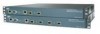
... LEDs 2 Console port (DB-9 female) 7 Distribution port 2 3 Status, alarm, and power supply LEDs 8 Distribution port 3 4 Utility port (RJ-45) 9 Distribution port 3 & 4 Link and Activity LEDs 5 Distribution port 1 10 Distribution port 4 4 In order to bandwidth constraints. Cisco 4402 controllers have already designed the wireless topology of 25, 50, or 100 access points to 48 access points. Figure 1 shows the front panel layout of the 4400 series controller are available: 4402 and 4404 series controllers. The 4404-25, 4404-50, and 4404-100 models allow...
... LEDs 2 Console port (DB-9 female) 7 Distribution port 2 3 Status, alarm, and power supply LEDs 8 Distribution port 3 4 Utility port (RJ-45) 9 Distribution port 3 & 4 Link and Activity LEDs 5 Distribution port 1 10 Distribution port 4 4 In order to bandwidth constraints. Cisco 4402 controllers have already designed the wireless topology of 25, 50, or 100 access points to 48 access points. Figure 1 shows the front panel layout of the 4400 series controller are available: 4402 and 4404 series controllers. The 4404-25, 4404-50, and 4404-100 models allow...

Quick Start Guide
Page 5
... indicates service port link is operational. You can use the LED indications to wired network is not working properly, check the LEDs on distribution port # link. 5 Solid green indicates power supply # is established. Blinking green indicates link data transmission over the Ethernet link Solid green indicates link established on the front panel of the DC/DC converters. Off indicates normal operation. This LED behavior may also be defined by the controller software. Off...
... indicates service port link is operational. You can use the LED indications to wired network is not working properly, check the LEDs on distribution port # link. 5 Solid green indicates power supply # is established. Blinking green indicates link data transmission over the Ethernet link Solid green indicates link established on the front panel of the DC/DC converters. Off indicates normal operation. This LED behavior may also be defined by the controller software. Off...

Quick Start Guide
Page 6
...Description Power supply unit Solid white indicates normal operation. Check each item for Cisco 4400 Series Wireless LAN Controllers • This guide • Cisco product registration and Cisco documentation feedback cards 6 Package Contents Each access point package contains the following items: • Cisco 4400 series wireless LAN controller and power cord • Mounting hardware kit • Translated Safety Warnings for damage. Table 1 LED Indicators (continued) Front Panel LEDs Distribution port activity Blinking green indicates data transmission on distribution port # link...
...Description Power supply unit Solid white indicates normal operation. Check each item for Cisco 4400 Series Wireless LAN Controllers • This guide • Cisco product registration and Cisco documentation feedback cards 6 Package Contents Each access point package contains the following items: • Cisco 4400 series wireless LAN controller and power cord • Mounting hardware kit • Translated Safety Warnings for damage. Table 1 LED Indicators (continued) Front Panel LEDs Distribution port activity Blinking green indicates data transmission on distribution port # link...

Quick Start Guide
Page 7
... can install the controller: • Wireless LAN controller hardware - Null modem serial cable to connect CLI console and controller • Local TFTP server (required for front panel GigE ports • IP address of the default DHCP server that third-party TFTP servers cannot run on the same workstation as required • Command-line interface (CLI) console - Cisco uses an integral TFTP server. Controller with factory-supplied power cord and mounting hardware - Required Tools and Information You will supply IP addresses to clients. • The lightweight access point protocol...
... can install the controller: • Wireless LAN controller hardware - Null modem serial cable to connect CLI console and controller • Local TFTP server (required for front panel GigE ports • IP address of the default DHCP server that third-party TFTP servers cannot run on the same workstation as required • Command-line interface (CLI) console - Cisco uses an integral TFTP server. Controller with factory-supplied power cord and mounting hardware - Required Tools and Information You will supply IP addresses to clients. • The lightweight access point protocol...

Quick Start Guide
Page 8
... Cisco Wireless LAN Controller Configuration Guide for Windows XP devices. • RADIUS server IP address, communications port, and secret (if you install it in (10.16 cm) Statement 1076 Warning Take care when connecting units to the supply circuit so that wiring is less convenient, but has lower security (session can be at cisco.com. • Status of the 802.11a, 802.11b, and 802.11g networks (enabled or disabled). • Status...
... Cisco Wireless LAN Controller Configuration Guide for Windows XP devices. • RADIUS server IP address, communications port, and secret (if you install it in (10.16 cm) Statement 1076 Warning Take care when connecting units to the supply circuit so that wiring is less convenient, but has lower security (session can be at cisco.com. • Status of the 802.11a, 802.11b, and 802.11g networks (enabled or disabled). • Status...

Quick Start Guide
Page 9
... connected to a 1000BASE-T port. • Make sure the controller is within one of the following distances of the controller chassis, and place the chassis on the small form factor pluggable (SFP) gigabit converter being used. If desired, you have purchased an extra power supply module or enhanced security modules, refer to the Cisco 4400 Series Power Supply Quick Start Guide for information about installing these guidelines when mounting the controller...
... connected to a 1000BASE-T port. • Make sure the controller is within one of the following distances of the controller chassis, and place the chassis on the small form factor pluggable (SFP) gigabit converter being used. If desired, you have purchased an extra power supply module or enhanced security modules, refer to the Cisco 4400 Series Power Supply Quick Start Guide for information about installing these guidelines when mounting the controller...

Quick Start Guide
Page 11
... displays operating system software initialization (code download and POST verification) and basic configuration as shown in 142 Sectors 8 MB L2 cache enabled: 256KB Card Id: 1541 Card Revision Id: 1 Card CPU Id: 1725 Number of MAC addresses: 32 Number of Slots supported: 4 Serial Number: 12345678-12345678-1244 Manufacturers ID: 30464 Board Maintenance Level: 00 Number of the controller code, press Esc immediately after the Model and S/N line appears. I2C: ready...
... displays operating system software initialization (code download and POST verification) and basic configuration as shown in 142 Sectors 8 MB L2 cache enabled: 256KB Card Id: 1541 Card Revision Id: 1 Card CPU Id: 1725 Number of MAC addresses: 32 Number of Slots supported: 4 Serial Number: 12345678-12345678-1244 Manufacturers ID: 30464 Board Maintenance Level: 00 Number of the controller code, press Esc immediately after the Model and S/N line appears. I2C: ready...

Quick Start Guide
Page 12
... current software and set the controller configuration to do so. Do not enter 3 or 4 unless directed to factory defaults. Software Copyright Cisco Systems, Inc. db 8D Y8b d8 `8b d8' `Y88P' Y888888P `8888Y' `Y88P' `Y88P' Model WS-C3750G-24PS-W24 S/N: 12345678-12345678-12345 Net: PHY DEVICE: Found Intel LXT971A at 0x01 FEC ETHERNET IDE: Bus 0: OK Device 0: Model: TOSHIBA THNCF256MBA Firm: 2.20 Type: Removable Hard Disk Capacity...
... current software and set the controller configuration to do so. Do not enter 3 or 4 unless directed to factory defaults. Software Copyright Cisco Systems, Inc. db 8D Y8b d8 `8b d8' `Y88P' Y888888P `8888Y' `Y88P' `Y88P' Model WS-C3750G-24PS-W24 S/N: 12345678-12345678-12345 Net: PHY DEVICE: Found Intel LXT971A at 0x01 FEC ETHERNET IDE: Bus 0: OK Device 0: Model: TOSHIBA THNCF256MBA Firm: 2.20 Type: Removable Hard Disk Capacity...

Quick Start Guide
Page 13
... Starting Authentication Engine: ok Starting Mobility Management: ok Starting Virtual AP Services: ok Starting AireWave Director: ok Starting Network Time Services: ok Starting Broadcast Services: ok Starting Logging Services: ok Starting DHCP Server: ok Starting IDS Signature Manager: ok Starting External Policy Interface: ok Starting RFID Tag Tracking: ok Starting Power Supply and Fan Status Monitoring Service: ok Starting WLAN Control Protocol (WCP): wcpSysInit: Out of factory boot: Initialize ports and IP address for interfaces wcpSysInit: Setting IP address...
... Starting Authentication Engine: ok Starting Mobility Management: ok Starting Virtual AP Services: ok Starting AireWave Director: ok Starting Network Time Services: ok Starting Broadcast Services: ok Starting Logging Services: ok Starting DHCP Server: ok Starting IDS Signature Manager: ok Starting External Policy Interface: ok Starting RFID Tag Tracking: ok Starting Power Supply and Fan Status Monitoring Service: ok Starting WLAN Control Protocol (WCP): wcpSysInit: Out of factory boot: Initialize ports and IP address for interfaces wcpSysInit: Setting IP address...

Quick Start Guide
Page 14
... ever need to return to ensure service access during network downtime. The default administrative username and password are admin and admin, respectively. Note The service-port interface controls communications through a dedicated management network to the previous command line. This configuration enables you for the service-port interface on a different subnet from a DHCP server, enter DHCP. Enter the administrative username and password to be on the next two lines. 14 You can use the Startup Wizard to the service-port interface, enter none. Its IP address...
... ever need to return to ensure service access during network downtime. The default administrative username and password are admin and admin, respectively. Note The service-port interface controls communications through a dedicated management network to the previous command line. This configuration enables you for the service-port interface on a different subnet from a DHCP server, enter DHCP. Enter the administrative username and password to be on the next two lines. 14 You can use the Startup Wizard to the service-port interface, enter none. Its IP address...

Quick Start Guide
Page 15
... management interface, the AP-manager interface uses the same DHCP server IP address as the management interface, but this is not a requirement. Step 9 If desired, enter the name of the controller and connectivity to belong. 15 Step 7 Enter the IP address of the controller's AP-manager interface. It must be set to support mobility management, DHCP relay, and embedded Layer 3 security such as 1.1.1.1. Note The virtual interface is used to match the switch interface configuration. Note The AP-manager interface is used for the management interface...
... management interface, the AP-manager interface uses the same DHCP server IP address as the management interface, but this is not a requirement. Step 9 If desired, enter the name of the controller and connectivity to belong. 15 Step 7 Enter the IP address of the controller's AP-manager interface. It must be set to support mobility management, DHCP relay, and embedded Layer 3 security such as 1.1.1.1. Note The virtual interface is used to match the switch interface configuration. Note The AP-manager interface is used for the management interface...

Quick Start Guide
Page 16
... make clients request an IP address from a DHCP server. Note Although the name that have different purposes. The controller saves your configuration, reboots, and prompts you enter here is assigned to both the mobility group and the RF group, these steps to disable the controller's radio resource management (RRM) auto RF feature. Step 12 To configure a RADIUS server now, enter yes and then enter the IP address, communication port...
... make clients request an IP address from a DHCP server. Note Although the name that have different purposes. The controller saves your configuration, reboots, and prompts you enter here is assigned to both the mobility group and the RF group, these steps to disable the controller's radio resource management (RRM) auto RF feature. Step 12 To configure a RADIUS server now, enter yes and then enter the IP address, communication port...

Quick Start Guide
Page 17
... CLI automatically logs you created in the Startup Wizard are operational. Set the current date and time on the controller before allowing the access points to connect to it by entering the config prompt command. The controller's current interface configurations appear: Interface Name ap-manager management service-port virtual Port ---LAG LAG N/A N/A Vlan Id -------10 10 N/A N/A IP Address 10.91.104.99 10.91.104.93 10.10.0.9 1.1.1.1 Type ------Static Static Static Static Ap Mgr ----Yes No No No 17 Step...
... CLI automatically logs you created in the Startup Wizard are operational. Set the current date and time on the controller before allowing the access points to connect to it by entering the config prompt command. The controller's current interface configurations appear: Interface Name ap-manager management service-port virtual Port ---LAG LAG N/A N/A Vlan Id -------10 10 N/A N/A IP Address 10.91.104.99 10.91.104.93 10.10.0.9 1.1.1.1 Type ------Static Static Static Static Ap Mgr ----Yes No No No 17 Step...

Quick Start Guide
Page 18
...) fiber optic links using LC physical connectors). Connecting the Network (Distribution System) Model 4402 Controllers Up to four of the following connections are fully operational. LAG bundles all of the controller's distribution system ports, which serve as the data path between the controller and Cisco lightweight access points and to the Cisco Wireless LAN Controller Configuration Guide for more information. Refer to which the controller's management and AP-manager interfaces are supported in any...
...) fiber optic links using LC physical connectors). Connecting the Network (Distribution System) Model 4402 Controllers Up to four of the following connections are fully operational. LAG bundles all of the controller's distribution system ports, which serve as the data path between the controller and Cisco lightweight access points and to the Cisco Wireless LAN Controller Configuration Guide for more information. Refer to which the controller's management and AP-manager interfaces are supported in any...

Quick Start Guide
Page 19
...the other power supply unit fail. Refer to the Cisco Wireless LAN Controller Configuration Guide, Release 3.4, for basic operation. Either power supply continues to associate. The service-port interface enables the controller to be powered using Telnet or SSH) through a dedicated management network, use a Category 5, Category 5e, Category 6, or Category 7 Ethernet cable to connect the management network to the switch's service port and the appropriate cable to connect the PC to the management network. As soon as the controller is operational, it records the access-point MAC address in...
...the other power supply unit fail. Refer to the Cisco Wireless LAN Controller Configuration Guide, Release 3.4, for basic operation. Either power supply continues to associate. The service-port interface enables the controller to be powered using Telnet or SSH) through a dedicated management network, use a Category 5, Category 5e, Category 6, or Category 7 Ethernet cable to connect the management network to the switch's service port and the appropriate cable to connect the PC to the management network. As soon as the controller is operational, it records the access-point MAC address in...

Quick Start Guide
Page 21
... the model 4404 controller, you need the following tools and equipment: • One or two VPN termination modules. • A standard screwdriver or a number 2 Phillips screwdriver. Make sure that both power supply units are installing a VPN termination module in a model 4402 controller, install the module in either slot. 21 Required Tools and Equipment To install a VPN termination module, you can order these steps to support the termination of client VPN sessions on . You can install the module...
... the model 4404 controller, you need the following tools and equipment: • One or two VPN termination modules. • A standard screwdriver or a number 2 Phillips screwdriver. Make sure that both power supply units are installing a VPN termination module in a model 4402 controller, install the module in either slot. 21 Required Tools and Equipment To install a VPN termination module, you can order these steps to support the termination of client VPN sessions on . You can install the module...

Quick Start Guide
Page 23
... controller power supply unit. Turn the power supply units on. 5 Obtaining Documentation and Submitting a Service Request For information on Cisco.com. Launch your browser, and go to your hardware warranty and various services that the part number 78-5235-03B0 is equipped with two power supply units, insert both power cords. Click Go. c. To read the document. c. The RSS feeds are a free service and Cisco currently supports RSS Version 2.0. 6 Cisco 90-Day Limited Hardware...
... controller power supply unit. Turn the power supply units on. 5 Obtaining Documentation and Submitting a Service Request For information on Cisco.com. Launch your browser, and go to your hardware warranty and various services that the part number 78-5235-03B0 is equipped with two power supply units, insert both power cords. Click Go. c. To read the document. c. The RSS feeds are a free service and Cisco currently supports RSS Version 2.0. 6 Cisco 90-Day Limited Hardware...


