
Hardware Installation Guide
Page 8
... 10/100 and 10/100/1000 Ports 2-6 SFP Module Slots 2-7 SFP Modules 2-7 LEDs 2-8 System LED 2-9 RPS LED 2-9 Master LED 2-10 Port LEDs and Modes 2-10 Rear Panel Description 2-14 StackWise Ports 2-15 Power Connectors 2-16 Internal Power Supply Connector 2-16 Cisco ...RPS Connector 2-16 Console Port 2-17 Management Options 2-18 Network Configurations 2-19 Switch Installation 3-1 Preparing for Installation 3-1 Warnings 3-2 EMC Regulatory Statements 3-4 Catalyst...
... 10/100 and 10/100/1000 Ports 2-6 SFP Module Slots 2-7 SFP Modules 2-7 LEDs 2-8 System LED 2-9 RPS LED 2-9 Master LED 2-10 Port LEDs and Modes 2-10 Rear Panel Description 2-14 StackWise Ports 2-15 Power Connectors 2-16 Internal Power Supply Connector 2-16 Cisco ...RPS Connector 2-16 Console Port 2-17 Management Options 2-18 Network Configurations 2-19 Switch Installation 3-1 Preparing for Installation 3-1 Warnings 3-2 EMC Regulatory Statements 3-4 Catalyst...

Hardware Installation Guide
Page 12
...INDEX Translated Safety Warnings E-1 Attaching the Cisco RPS (model PWR300-AC-RPS-N1) E-1 Attaching the Cisco RPS (model PWR675-AC-RPS-N1) E-2 Installation Warning E-4 Installation Instructions E-5 Jewelry Removal Warning E-6 Stacking the Chassis Warning E-8 Main Disconnecting Device E-10 Grounded Equipment Warning E-11 Installing or ... and Servicing E-19 Redundant Power Supply Connection Warning E-24 Switch Installation Warning E-25 Restricted Area E-27 Ethernet Cable Shielding in Offices E-28 Laser Beam Exposure E-30 Laser Radiation E-31 E-32 Catalyst 3750 Switch Hardware Installation Guide...
...INDEX Translated Safety Warnings E-1 Attaching the Cisco RPS (model PWR300-AC-RPS-N1) E-1 Attaching the Cisco RPS (model PWR675-AC-RPS-N1) E-2 Installation Warning E-4 Installation Instructions E-5 Jewelry Removal Warning E-6 Stacking the Chassis Warning E-8 Main Disconnecting Device E-10 Grounded Equipment Warning E-11 Installing or ... and Servicing E-19 Redundant Power Supply Connection Warning E-24 Switch Installation Warning E-25 Restricted Area E-27 Ethernet Cable Shielding in Offices E-28 Laser Beam Exposure E-30 Laser Radiation E-31 E-32 Catalyst 3750 Switch Hardware Installation Guide...

Hardware Installation Guide
Page 14
... will use the product, provided that the fan and power supply warranty is limited to five (5) years from the announcement of the Return Materials Authorization (RMA) request. The Cisco warranty page appears. c. Cisco reserves the right to refund the purchase price as the... contact the Cisco service and support website for Hardware Cisco or its exclusive warranty remedy. Enter this part number in Adobe Portable Document Format (PDF). Replacement, Repair, or Refund Policy for assistance: http://www.cisco.com/public/Support_root.shtml. Catalyst 3750 Switch Hardware...
... will use the product, provided that the fan and power supply warranty is limited to five (5) years from the announcement of the Return Materials Authorization (RMA) request. The Cisco warranty page appears. c. Cisco reserves the right to refund the purchase price as the... contact the Cisco service and support website for Hardware Cisco or its exclusive warranty remedy. Enter this part number in Adobe Portable Document Format (PDF). Replacement, Repair, or Refund Policy for assistance: http://www.cisco.com/public/Support_root.shtml. Catalyst 3750 Switch Hardware...

Hardware Installation Guide
Page 42
... only full-duplex mode • The Catalyst 3750 switches support stacking. Connection for optional Cisco RPS 300 redundant power system that operates on AC input and supplies backup DC power output to nine switches in half-duplex mode at 10 or 100 Mbps. • Configuration - Catalyst 3750G-24T-24 10/100/1000 Ethernet ports - Catalyst 3750G-12S-12 SFP module slots •...
... only full-duplex mode • The Catalyst 3750 switches support stacking. Connection for optional Cisco RPS 300 redundant power system that operates on AC input and supplies backup DC power output to nine switches in half-duplex mode at 10 or 100 Mbps. • Configuration - Catalyst 3750G-24T-24 10/100/1000 Ethernet ports - Catalyst 3750G-12S-12 SFP module slots •...

Hardware Installation Guide
Page 43
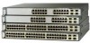
... 19 20 21 22 23 24 23X 14X 24X Catalyst 3750 SERIES 1 2 1 2 1 10/100 ports 2 SFP module ports The 10/100/1000 ports on AC input and supplies backup DC power output to 28. 78-15136-02 Catalyst 3750 Switch Hardware Installation Guide 2-3 Connection for optional Cisco RPS 675 redundant power system that operates on the Catalyst 3750G-24T and 3750G-24TS...
... 19 20 21 22 23 24 23X 14X 24X Catalyst 3750 SERIES 1 2 1 2 1 10/100 ports 2 SFP module ports The 10/100/1000 ports on AC input and supplies backup DC power output to 28. 78-15136-02 Catalyst 3750 Switch Hardware Installation Guide 2-3 Connection for optional Cisco RPS 675 redundant power system that operates on the Catalyst 3750G-24T and 3750G-24TS...

Hardware Installation Guide
Page 49
...in a switch has failed, and the RPS is connected and ready to the 10/100 and 10/100/1000 Ports" section on self-test (POST), see the "Connecting to provide back-up power, if required. If it is not functioning properly. Chapter 2 Product Overview Front... connected but is providing power to another device (redundancy has been allocated to this device). 78-15136-02 Catalyst 3750 Switch Hardware Installation Guide 2-9 Table 2-1 System LED Color Off Green Amber System Status System is functioning properly. Contact Cisco Systems. The internal power supply in a fault condition....
...in a switch has failed, and the RPS is connected and ready to the 10/100 and 10/100/1000 Ports" section on self-test (POST), see the "Connecting to provide back-up power, if required. If it is not functioning properly. Chapter 2 Product Overview Front... connected but is providing power to another device (redundancy has been allocated to this device). 78-15136-02 Catalyst 3750 Switch Hardware Installation Guide 2-9 Table 2-1 System LED Color Off Green Amber System Status System is functioning properly. Contact Cisco Systems. The internal power supply in a fault condition....

Hardware Installation Guide
Page 56
Internal Power Supply Connector The internal power supply is powered through the internal power supply. Use the supplied AC power cord to connect the AC power connector to the RPS receptacle. 2-16 Catalyst 3750 Switch Hardware Installation Guide 78-15136-02 Cisco RPS 300 The Cisco RPS 300 has two output levels: -48V and 12V with a total maximum output power of switches. Warning Attach only...
Internal Power Supply Connector The internal power supply is powered through the internal power supply. Use the supplied AC power cord to connect the AC power connector to the RPS receptacle. 2-16 Catalyst 3750 Switch Hardware Installation Guide 78-15136-02 Cisco RPS 300 The Cisco RPS 300 has two output levels: -48V and 12V with a total maximum output power of switches. Warning Attach only...

Hardware Installation Guide
Page 57
... an RJ-45-to the RPS receptacle. For more information on page B-1. 78-15136-02 Catalyst 3750 Switch Hardware Installation Guide 2-17 Use the supplied RPS connector cable to connect the RPS to the Cisco RPS 675 Redundant Power System Hardware Installation Guide. For console port and adapter pinout information, see the "Connector and...
... an RJ-45-to the RPS receptacle. For more information on page B-1. 78-15136-02 Catalyst 3750 Switch Hardware Installation Guide 2-17 Use the supplied RPS connector cable to connect the RPS to the Cisco RPS 675 Redundant Power System Hardware Installation Guide. For console port and adapter pinout information, see the "Connector and...

Hardware Installation Guide
Page 68
... page 3-8 • Powering On the Switch and Running POST, page 3-10 Connecting a PC or Terminal to the Console Port To connect a PC to the console port, use the supplied RJ-45-to power on page B-6. Six...power the switch and verify that adapter from Cisco. To connect the switch console port to a terminal, you need to provide a RJ-45-to one of the StackWise cable, the 0.5-meter cable is supplied...possible. One cable guide and one black Phillips machine screw for attaching the brackets to the switch (Catalyst 3750-24TS, 3750G-24T, and 3750-48TS switches) - You can order a kit (part ...
... page 3-8 • Powering On the Switch and Running POST, page 3-10 Connecting a PC or Terminal to the Console Port To connect a PC to the console port, use the supplied RJ-45-to power on page B-6. Six...power the switch and verify that adapter from Cisco. To connect the switch console port to a terminal, you need to provide a RJ-45-to one of the StackWise cable, the 0.5-meter cable is supplied...possible. One cable guide and one black Phillips machine screw for attaching the brackets to the switch (Catalyst 3750-24TS, 3750G-24T, and 3750-48TS switches) - You can order a kit (part ...

Hardware Installation Guide
Page 72
...Stack Chapter 3 Switch Installation Planning the Stack If you plan to stack your Cisco supplier. If you don't specify the length of the switch. Make sure that there is supplied by default. For cable numbers, see the "StackWise Ports" section on page ..., read these sections: • Planning Considerations, page 3-12 • Powering Considerations, page 3-13 • Cabling Considerations, page 3-14 • Recommended Cabling Configurations, page 3-15 Planning Considerations Before connecting the Catalyst 3750 switches in a stack, observe these planning considerations: • Size of...
...Stack Chapter 3 Switch Installation Planning the Stack If you plan to stack your Cisco supplier. If you don't specify the length of the switch. Make sure that there is supplied by default. For cable numbers, see the "StackWise Ports" section on page ..., read these sections: • Planning Considerations, page 3-12 • Powering Considerations, page 3-13 • Cabling Considerations, page 3-14 • Recommended Cabling Configurations, page 3-15 Planning Considerations Before connecting the Catalyst 3750 switches in a stack, observe these planning considerations: • Size of...

Hardware Installation Guide
Page 90
... refer to the left or right bracket. 3-30 Catalyst 3750 Switch Hardware Installation Guide 78-15136-02 See the "Connecting to a Power Source" section on page 3-46 to an SFP Module" section on page 1-6. See the "Connecting to the 10/100 and 10/100/1000 Ports" section on page 3-44 and the... "Connecting to complete the installation. To use the CLI, enter commands at the Switch> prompt through the console port by using a terminal program or through the network by using Telnet. Use the supplied black screw,...
... refer to the left or right bracket. 3-30 Catalyst 3750 Switch Hardware Installation Guide 78-15136-02 See the "Connecting to a Power Source" section on page 3-46 to an SFP Module" section on page 1-6. See the "Connecting to the 10/100 and 10/100/1000 Ports" section on page 3-44 and the... "Connecting to complete the installation. To use the CLI, enter commands at the Switch> prompt through the console port by using a terminal program or through the network by using Telnet. Use the supplied black screw,...

Hardware Installation Guide
Page 95
... the Switch on a Wall Installing the Switch Catalyst 3750 SERIES 24X 23X 24 22 23 20 21 18 19 14X 16 17 14 15 13X 13 12X 11X 10 11 12 1X 2X 8 9 67 45 23 1 MODE STASCPKEDEUDPSLTXAMTASRTPRSSYST 1 1 86570 1 User-supplied screws After the switch is mounted on the...Connect to the Console Port" section on page 1-4 and the "Starting the Terminal Emulation Software" section on page 1-6. • Power on page 3-13. 78-15136-02 Catalyst 3750 Switch Hardware Installation Guide 3-35 See the "Connecting to the console port, and start the emulation software. If the switches...
... the Switch on a Wall Installing the Switch Catalyst 3750 SERIES 24X 23X 24 22 23 20 21 18 19 14X 16 17 14 15 13X 13 12X 11X 10 11 12 1X 2X 8 9 67 45 23 1 MODE STASCPKEDEUDPSLTXAMTASRTPRSSYST 1 1 86570 1 User-supplied screws After the switch is mounted on the...Connect to the Console Port" section on page 1-4 and the "Starting the Terminal Emulation Software" section on page 1-6. • Power on page 3-13. 78-15136-02 Catalyst 3750 Switch Hardware Installation Guide 3-35 See the "Connecting to the console port, and start the emulation software. If the switches...
Hardware Installation Guide
Page 153
...between the switch and your switches, refer to a grounded AC outlet. (Optional) If you have a stack, power on page 3-13 for more information. 78-15136-02 Catalyst 3750 Switch Hardware Installation Guide D-9 Step 1 Step 2 Step 3 Start the terminal-emulation program if you have ...stacked your PC or terminal possible. Start a terminal-emulation session. Connect the other end of the supplied AC power cord to the power connector on self-test...
...between the switch and your switches, refer to a grounded AC outlet. (Optional) If you have a stack, power on page 3-13 for more information. 78-15136-02 Catalyst 3750 Switch Hardware Installation Guide D-9 Step 1 Step 2 Step 3 Start the terminal-emulation program if you have ...stacked your PC or terminal possible. Start a terminal-emulation session. Connect the other end of the supplied AC power cord to the power connector on self-test...
Hardware Installation Guide
Page 195
... 10/100 ports B-6 port LEDs 2-10 to 2-12 port modes changing 2-8 LEDs 2-10, 2-11 See also mode button ports 10/100 2-6 10/100/1000 2-3 numbering of 10/100 2-6 numbering of 10/100/1000 2-6 POST LEDs 4-2 results 4-1 running at powerup 1-4 power connecting to 3-10 connectors 2-14, 2-16 specifications A-1 to A-5 power on 3-10 power supply AC power outlet... R rack-mounting 3-18 to 3-36 rear panel clearance 3-6 description 2-14 to 2-17 redundant power supply See RPS regulatory statements, EMC 3-4 removing SFP modules 3-43 to 3-44 78-15136-02 Catalyst 3750 Switch Hardware Installation Guide IN-5
... 10/100 ports B-6 port LEDs 2-10 to 2-12 port modes changing 2-8 LEDs 2-10, 2-11 See also mode button ports 10/100 2-6 10/100/1000 2-3 numbering of 10/100 2-6 numbering of 10/100/1000 2-6 POST LEDs 4-2 results 4-1 running at powerup 1-4 power connecting to 3-10 connectors 2-14, 2-16 specifications A-1 to A-5 power on 3-10 power supply AC power outlet... R rack-mounting 3-18 to 3-36 rear panel clearance 3-6 description 2-14 to 2-17 redundant power supply See RPS regulatory statements, EMC 3-4 removing SFP modules 3-43 to 3-44 78-15136-02 Catalyst 3750 Switch Hardware Installation Guide IN-5

