
Hardware Installation Guide
Page 8
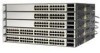
... 2-9 RPS LED 2-9 Master LED 2-10 Port LEDs and Modes 2-10 Rear Panel Description 2-14 StackWise Ports 2-15 Power Connectors 2-16 Internal Power Supply Connector 2-16 Cisco RPS Connector 2-16 Console Port 2-17 Management Options 2-18 Network Configurations 2-19 Switch Installation 3-1 Preparing for Installation 3-1 Warnings 3-2 EMC Regulatory Statements 3-4 Catalyst 3750 Switch Hardware Installation Guide vi 78-15136-02
... 2-9 RPS LED 2-9 Master LED 2-10 Port LEDs and Modes 2-10 Rear Panel Description 2-14 StackWise Ports 2-15 Power Connectors 2-16 Internal Power Supply Connector 2-16 Cisco RPS Connector 2-16 Console Port 2-17 Management Options 2-18 Network Configurations 2-19 Switch Installation 3-1 Preparing for Installation 3-1 Warnings 3-2 EMC Regulatory Statements 3-4 Catalyst 3750 Switch Hardware Installation Guide vi 78-15136-02

Hardware Installation Guide
Page 9
... Attaching Brackets to the Catalyst 3750G-24TS Switch 3-20 Attaching Brackets to the Catalyst 3750-24TS, 3750G-24T, 3750G-12S, and 3750-48TS Switches 3-25 Mounting the Switch in a Rack 3-28 Attaching the Cable Guide 3-30 Wall Mounting 3-32 Attaching the Brackets to the Switch for Wall-Mounting 3-32 Attaching the RPS Connector Cover 3-33 Mounting the...
... Attaching Brackets to the Catalyst 3750G-24TS Switch 3-20 Attaching Brackets to the Catalyst 3750-24TS, 3750G-24T, 3750G-12S, and 3750-48TS Switches 3-25 Mounting the Switch in a Rack 3-28 Attaching the Cable Guide 3-30 Wall Mounting 3-32 Attaching the Brackets to the Switch for Wall-Mounting 3-32 Attaching the RPS Connector Cover 3-33 Mounting the...

Hardware Installation Guide
Page 10
... Specifications A-1 B A P P E N D I X Connector and Cable Specifications B-1 Connector Specifications B-1 10/100/1000 Ports B-1 Connecting to 1000BASE-T Devices B-2 10/100 Ports B-3 SFP Module Ports B-5 Console Port B-6 Cable and Adapter Specifications B-6 Two Twisted-Pair Cable Pinouts B-6 Four Twisted-Pair Cable Pinouts for 10/100 Ports B-7 Four Twisted-Pair Cable Pinouts for 1000BASE-T Ports B-8 Catalyst 3750 Switch Hardware Installation...
... Specifications A-1 B A P P E N D I X Connector and Cable Specifications B-1 Connector Specifications B-1 10/100/1000 Ports B-1 Connecting to 1000BASE-T Devices B-2 10/100 Ports B-3 SFP Module Ports B-5 Console Port B-6 Cable and Adapter Specifications B-6 Two Twisted-Pair Cable Pinouts B-6 Four Twisted-Pair Cable Pinouts for 10/100 Ports B-7 Four Twisted-Pair Cable Pinouts for 1000BASE-T Ports B-8 Catalyst 3750 Switch Hardware Installation...

Hardware Installation Guide
Page 31
Chapter 1 Using Express Setup Figure 1-2 Ethernet Cable Powering On the Switch 89887 Powering On the Switch Complete these steps to power on the switch: Step 1 Connect one end of the AC power cord to the power connector on the switch rear panel, as shown in Figure 1-3. Figure 1-3 Connecting the Power 1 STACK 1 STACK 2 CONSOLE 1.2A-100R>06A-A2T4,IN05GV0-~60 HZ DSCPIENPCPO+IUWF1T2IEESvDRFISO@NUR1MP3RPAAELNYMUOATLE 97176 1 Switch 2 2 AC power cord 78-15136-02 Catalyst 3750 Switch Hardware Installation Guide 1-3
Chapter 1 Using Express Setup Figure 1-2 Ethernet Cable Powering On the Switch 89887 Powering On the Switch Complete these steps to power on the switch: Step 1 Connect one end of the AC power cord to the power connector on the switch rear panel, as shown in Figure 1-3. Figure 1-3 Connecting the Power 1 STACK 1 STACK 2 CONSOLE 1.2A-100R>06A-A2T4,IN05GV0-~60 HZ DSCPIENPCPO+IUWF1T2IEESvDRFISO@NUR1MP3RPAAELNYMUOATLE 97176 1 Switch 2 2 AC power cord 78-15136-02 Catalyst 3750 Switch Hardware Installation Guide 1-3

Hardware Installation Guide
Page 46
... in Appendix B, "Connector and Cable Specifications." When connecting the switch to workstations, servers, routers, and Cisco IP Phones, be sure to use a twisted four-pair, Category 5 cable for connections to a copper 10/100 or 10/100/1000 port on the switch, regardless the type ... the switch port negotiates the best connection (that both devices support and full-duplex transmission if the attached device supports it) and configures itself accordingly. Note On switches running Cisco IOS Release 12.1(14)EA1 or later, you can use a crossover cable. Catalyst 3750 Switch Hardware ...
... in Appendix B, "Connector and Cable Specifications." When connecting the switch to workstations, servers, routers, and Cisco IP Phones, be sure to use a twisted four-pair, Category 5 cable for connections to a copper 10/100 or 10/100/1000 port on the switch, regardless the type ... the switch port negotiates the best connection (that both devices support and full-duplex transmission if the attached device supports it) and configures itself accordingly. Note On switches running Cisco IOS Release 12.1(14)EA1 or later, you can use a crossover cable. Catalyst 3750 Switch Hardware ...

Hardware Installation Guide
Page 47
... slot. SFP Modules The Catalyst 3750 switch uses Gigabit Ethernet SFP modules to your SFP module documentation. 78-15136-02 Catalyst 3750 Switch Hardware Installation Guide 2-7 You use the SFP modules for Gigabit uplink connections to other switches. The Catalyst 3750 models support these Cisco SFP options: • ...providing the uplink interfaces when inserted in the Catalyst 3750 release notes. You can use fiber-optic cables with RJ-45 connectors to connect to a fiber-optic SFP module. You use Category 5 cable with LC or MT-RJ connectors to connect to a copper SFP module....
... slot. SFP Modules The Catalyst 3750 switch uses Gigabit Ethernet SFP modules to your SFP module documentation. 78-15136-02 Catalyst 3750 Switch Hardware Installation Guide 2-7 You use the SFP modules for Gigabit uplink connections to other switches. The Catalyst 3750 models support these Cisco SFP options: • ...providing the uplink interfaces when inserted in the Catalyst 3750 release notes. You can use fiber-optic cables with RJ-45 connectors to connect to a fiber-optic SFP module. You use Category 5 cable with LC or MT-RJ connectors to connect to a copper SFP module....

Hardware Installation Guide
Page 54
Rear Panel Description Chapter 2 Product Overview Rear Panel Description The switch rear panels have an AC power connector, an RPS connector, an RJ-45 console port, and two StackWise ports. (See Figure 2-8 and Figure 2-9.) Figure 2-8 Catalyst 3750-24TS, 3750G-24T, 3750G-12S, and 3750-48TS Rear Panel 86548 STACK 1 STACK 2 CONSOLE 1.6A-100R>09A-A2T0...
Rear Panel Description Chapter 2 Product Overview Rear Panel Description The switch rear panels have an AC power connector, an RPS connector, an RJ-45 console port, and two StackWise ports. (See Figure 2-8 and Figure 2-9.) Figure 2-8 Catalyst 3750-24TS, 3750G-24T, 3750G-12S, and 3750-48TS Rear Panel 86548 STACK 1 STACK 2 CONSOLE 1.6A-100R>09A-A2T0...

Hardware Installation Guide
Page 55
...+IUWF1TI2EESvDRFISO@NUR1MP7RPAaELNYMUOATLE 1 23 4 5 1 StackWise ports 2 RJ-45 console port 3 Fan exhaust 4 AC power connector 5 RPS connector StackWise Ports The Catalyst 3750 switch ships with a 0.5-meter StackWise cable (72-2632-XX CABASY) that you can order these StackWise cables from your Cisco sales representative: • CAB-STACK-50CM= (0.5-meter cable) • CAB-STACK-1M= (1-meter cable...
...+IUWF1TI2EESvDRFISO@NUR1MP7RPAaELNYMUOATLE 1 23 4 5 1 StackWise ports 2 RJ-45 console port 3 Fan exhaust 4 AC power connector 5 RPS connector StackWise Ports The Catalyst 3750 switch ships with a 0.5-meter StackWise cable (72-2632-XX CABASY) that you can order these StackWise cables from your Cisco sales representative: • CAB-STACK-50CM= (0.5-meter cable) • CAB-STACK-1M= (1-meter cable...

Hardware Installation Guide
Page 56
... to connect the RPS to the RPS receptacle. 2-16 Catalyst 3750 Switch Hardware Installation Guide 78-15136-02 Cisco RPS 300 The Cisco RPS 300 has two output levels: -48V and 12V with a total maximum output power of switches. Cisco RPS Connector Specific Cisco RPS modes support specific Catalyst 3750 switches: • Cisco RPS 300 (model PWR300-AC-RPS-N1) supports...
... to connect the RPS to the RPS receptacle. 2-16 Catalyst 3750 Switch Hardware Installation Guide 78-15136-02 Cisco RPS 300 The Cisco RPS 300 has two output levels: -48V and 12V with a total maximum output power of switches. Cisco RPS Connector Specific Cisco RPS modes support specific Catalyst 3750 switches: • Cisco RPS 300 (model PWR300-AC-RPS-N1) supports...

Hardware Installation Guide
Page 57
..., preventing loss of 675W. Use the supplied RPS connector cable to connect the RPS to -DB-25 female DTE adapter. For more information on page B-1. 78-15136-02 Catalyst 3750 Switch Hardware Installation Guide 2-17 The RPS is a redundant power system that adapter from Cisco. The Cisco RPS 675 has two output levels: -48V and...
..., preventing loss of 675W. Use the supplied RPS connector cable to connect the RPS to -DB-25 female DTE adapter. For more information on page B-1. 78-15136-02 Catalyst 3750 Switch Hardware Installation Guide 2-17 The RPS is a redundant power system that adapter from Cisco. The Cisco RPS 675 has two output levels: -48V and...
Hardware Installation Guide
Page 67
... each item for attaching the brackets to the switch (Catalyst 3750G-24TS switch) 78-15136-02 Catalyst 3750 Switch Hardware Installation Guide 3-7 If any item is missing or damaged, contact your Cisco representative or reseller for mounting the switch on a table - Return all packing material...cables. • Airflow around the switch and through the vents is unrestricted. • Temperature around it . Chapter 3 Switch Installation Preparing for Installation Make sure that might be greater than normal room temperature. Rear-panel power connector is within reach of an AC ...
... each item for attaching the brackets to the switch (Catalyst 3750G-24TS switch) 78-15136-02 Catalyst 3750 Switch Hardware Installation Guide 3-7 If any item is missing or damaged, contact your Cisco representative or reseller for mounting the switch on a table - Return all packing material...cables. • Airflow around the switch and through the vents is unrestricted. • Temperature around it . Chapter 3 Switch Installation Preparing for Installation Make sure that might be greater than normal room temperature. Rear-panel power connector is within reach of an AC ...

Hardware Installation Guide
Page 68
... machine screw for attaching the cable guide to a rack - One redundant power system (RPS) connector cover (for Installation Chapter 3 Switch Installation - Four Phillips truss-head screws (for attaching the RPS cover) - StackWise cable: 0.5-meter, 1-meter...switch and verify that adapter from Cisco. The terminal-emulation software-frequently a PC application such as Hyperterminal or Procomm Plus-makes communication between the switch and your PC or terminal possible. You can order a kit (part number ACS-DSBUASYN=) containing that the switch passes POST. Catalyst 3750 Switch...
... machine screw for attaching the cable guide to a rack - One redundant power system (RPS) connector cover (for Installation Chapter 3 Switch Installation - Four Phillips truss-head screws (for attaching the RPS cover) - StackWise cable: 0.5-meter, 1-meter...switch and verify that adapter from Cisco. The terminal-emulation software-frequently a PC application such as Hyperterminal or Procomm Plus-makes communication between the switch and your PC or terminal possible. You can order a kit (part number ACS-DSBUASYN=) containing that the switch passes POST. Catalyst 3750 Switch...

Hardware Installation Guide
Page 69
...8226; 8 data bits • 1 stop bit • No parity • None (flow control) After you have gained access to the switch, you are using a PC or terminal. 78-15136-02 Catalyst 3750 Switch Hardware Installation Guide 3-9 Attach the DB-9 female DTE adapter of the PC or terminal to match these steps to connect... the PC or terminal to the switch: Step 1 Step 2 Step 3 Step 4 Configure the baud rate and character format of the RJ-45-to-DB-9 adapter cable to a PC, or attach an appropriate adapter to -DB-9 adapter cable, insert the RJ-45 connector into the console port, as shown in...
...8226; 8 data bits • 1 stop bit • No parity • None (flow control) After you have gained access to the switch, you are using a PC or terminal. 78-15136-02 Catalyst 3750 Switch Hardware Installation Guide 3-9 Attach the DB-9 female DTE adapter of the PC or terminal to match these steps to connect... the PC or terminal to the switch: Step 1 Step 2 Step 3 Step 4 Configure the baud rate and character format of the RJ-45-to-DB-9 adapter cable to a PC, or attach an appropriate adapter to -DB-9 adapter cable, insert the RJ-45 connector into the console port, as shown in...
Hardware Installation Guide
Page 70
.... Catalyst 3750 Switch Hardware Installation Guide 78-15136-02 To power on the switch, follow these steps: Step 1 Step 2 Make sure that you are connecting devices to the AC power connector on the switch. Preparing for information on connecting to the switch console port. See the "Power Connectors" section on page 2-16, and refer to the Cisco RPS...
.... Catalyst 3750 Switch Hardware Installation Guide 78-15136-02 To power on the switch, follow these steps: Step 1 Step 2 Make sure that you are connecting devices to the AC power connector on the switch. Preparing for information on connecting to the switch console port. See the "Power Connectors" section on page 2-16, and refer to the Cisco RPS...

Hardware Installation Guide
Page 92
... Attaching the 19-inch Brackets for Wall-Mounting, page 3-32 • Attaching the RPS Connector Cover, page 3-33 • Mounting the Switch on a wall, follow the instructions in this section show the Catalyst 3750G-24TS switch as an example. All the Catalyst 3750 switches are wall-mounted following the same procedures. Attaching the Brackets to the...
... Attaching the 19-inch Brackets for Wall-Mounting, page 3-32 • Attaching the RPS Connector Cover, page 3-33 • Mounting the Switch on a wall, follow the instructions in this section show the Catalyst 3750G-24TS switch as an example. All the Catalyst 3750 switches are wall-mounted following the same procedures. Attaching the Brackets to the...

Hardware Installation Guide
Page 93
...-head screws to attach the RPS connector cover to the switch, install an RPS connector cover on the Catalyst 3750G-24TS Switch 86571 STACK 1 STACK 2 CONSOLE [email protected] 1 2 3 1 Phillips pan-head screws 3 RPS connector 2 RPS connector cover 78-15136-02 Catalyst 3750 Switch Hardware Installation Guide 3-33 Figure 3-31 Attaching the RPS Connector Cover on the back of...
...-head screws to attach the RPS connector cover to the switch, install an RPS connector cover on the Catalyst 3750G-24TS Switch 86571 STACK 1 STACK 2 CONSOLE [email protected] 1 2 3 1 Phillips pan-head screws 3 RPS connector 2 RPS connector cover 78-15136-02 Catalyst 3750 Switch Hardware Installation Guide 3-33 Figure 3-31 Attaching the RPS Connector Cover on the back of...

Hardware Installation Guide
Page 94
...-A2T0,IN05GV0-~60 HZ [email protected] 1 2 3 1 Phillips pan-head screws 3 RPS connector 2 RPS connector cover Mounting the Switch on a wall with the front panel facing up . 86572 3-34 Catalyst 3750 Switch Hardware Installation Guide 78-15136-02 Mount the switch with the front panel facing up , as shown in Figure 3-33. Warning To comply...
...-A2T0,IN05GV0-~60 HZ [email protected] 1 2 3 1 Phillips pan-head screws 3 RPS connector 2 RPS connector cover Mounting the Switch on a wall with the front panel facing up . 86572 3-34 Catalyst 3750 Switch Hardware Installation Guide 78-15136-02 Mount the switch with the front panel facing up , as shown in Figure 3-33. Warning To comply...

Hardware Installation Guide
Page 97
Note Always use a Cisco-approved StackWise cable to align the connector correctly. Step 3 Step 4 Use the window in the StackWise cable to connect the switches. Caution Removing and installing the StackWise cable can shorten its useful life. Do not remove and... Switch Installation Connecting StackWise Cable to the StackWise ports: Step 1 Step 2 Remove the dust covers from dust. 78-15136-02 Catalyst 3750 Switch Hardware Installation Guide 3-37 Insert one end of the StackWise cable into the connector of the switch. For configuration information, refer to the switch ...
Note Always use a Cisco-approved StackWise cable to align the connector correctly. Step 3 Step 4 Use the window in the StackWise cable to connect the switches. Caution Removing and installing the StackWise cable can shorten its useful life. Do not remove and... Switch Installation Connecting StackWise Cable to the StackWise ports: Step 1 Step 2 Remove the dust covers from dust. 78-15136-02 Catalyst 3750 Switch Hardware Installation Guide 3-37 Insert one end of the StackWise cable into the connector of the switch. For configuration information, refer to the switch ...

Hardware Installation Guide
Page 98
Also make sure that you need to remove the StackWise cable from the connector, make sure to StackWise Ports Figure 3-34 Inserting the StackWise Cable in a StackWise Port Chapter 3 Switch Installation STACK 1 STACK 2 CONSOLE 86549 When you remove the correct screws from the StackWise port. Connecting StackWise Cable to fully unscrew the screws before removing the connector. See Figure 3-35 for correct removal procedures and Figure 3-36 for incorrect removal procedures. 3-38 Catalyst 3750 Switch Hardware Installation Guide 78-15136-02
Also make sure that you need to remove the StackWise cable from the connector, make sure to StackWise Ports Figure 3-34 Inserting the StackWise Cable in a StackWise Port Chapter 3 Switch Installation STACK 1 STACK 2 CONSOLE 86549 When you remove the correct screws from the StackWise port. Connecting StackWise Cable to fully unscrew the screws before removing the connector. See Figure 3-35 for correct removal procedures and Figure 3-36 for incorrect removal procedures. 3-38 Catalyst 3750 Switch Hardware Installation Guide 78-15136-02

Hardware Installation Guide
Page 101
... wrist strap to your wrist and to a bare metal surface on installing, removing, and cabling the SFP module, refer to the cables, the cable connector, or the optical interfaces in the SFP module. Figure 3-37 SFP Module with a Bale-Clasp Latch 86575 To insert an SFP module into SFP Module... an SFP module that you do not install or remove fiber-optic SFP modules with cables attached because of the SFP module. 78-15136-02 Catalyst 3750 Switch Hardware Installation Guide 3-41 Find the send (TX) and receive (RX) markings that identify the top side of the potential damage to your...
... wrist strap to your wrist and to a bare metal surface on installing, removing, and cabling the SFP module, refer to the cables, the cable connector, or the optical interfaces in the SFP module. Figure 3-37 SFP Module with a Bale-Clasp Latch 86575 To insert an SFP module into SFP Module... an SFP module that you do not install or remove fiber-optic SFP modules with cables attached because of the SFP module. 78-15136-02 Catalyst 3750 Switch Hardware Installation Guide 3-41 Find the send (TX) and receive (RX) markings that identify the top side of the potential damage to your...