
Installation Guide
Page 2
... instructions, it was probably caused by the Cisco equipment or one side or the other of California. This equipment has been tested and found to comply with the instruction manual, may result in the equipment no guarantee that interference will be required to correct any interference to use ... DAMAGES, INCLUDING, WITHOUT LIMITATION, LOST PROFITS OR LOSS OR DAMAGE TO DATA ARISING OUT OF THE USE OR INABILITY TO USE THIS MANUAL, EVEN IF CISCO OR ITS SUPPLIERS HAVE BEEN ADVISED OF THE POSSIBILITY OF SUCH DAMAGES. THE SOFTWARE LICENSE AND LIMITED WARRANTY FOR THE ACCOMPANYING PRODUCT ARE ...
... instructions, it was probably caused by the Cisco equipment or one side or the other of California. This equipment has been tested and found to comply with the instruction manual, may result in the equipment no guarantee that interference will be required to correct any interference to use ... DAMAGES, INCLUDING, WITHOUT LIMITATION, LOST PROFITS OR LOSS OR DAMAGE TO DATA ARISING OUT OF THE USE OR INABILITY TO USE THIS MANUAL, EVEN IF CISCO OR ITS SUPPLIERS HAVE BEEN ADVISED OF THE POSSIBILITY OF SUCH DAMAGES. THE SOFTWARE LICENSE AND LIMITED WARRANTY FOR THE ACCOMPANYING PRODUCT ARE ...
Installation Guide
Page 13
... als u een vertaling van de waarschuwing die bij het apparaat wordt geleverd, wilt raadplegen. BEWAAR DEZE INSTRUCTIES 78-6456-04 Catalyst 3500 Series XL Hardware Installation Guide xiii Warning IMPORTANT SAFETY INSTRUCTIONS This warning symbol means danger. Caution Means reader be familiar with...symbols: Note Means reader take note. Before you might do something that could result in the translated safety warnings that accompanied this manual. Use the statement number provided at the end of the hazards involved with electrical circuitry and be careful. Voordat u aan enige...
... als u een vertaling van de waarschuwing die bij het apparaat wordt geleverd, wilt raadplegen. BEWAAR DEZE INSTRUCTIES 78-6456-04 Catalyst 3500 Series XL Hardware Installation Guide xiii Warning IMPORTANT SAFETY INSTRUCTIONS This warning symbol means danger. Caution Means reader be familiar with...symbols: Note Means reader take note. Before you might do something that could result in the translated safety warnings that accompanied this manual. Use the statement number provided at the end of the hazards involved with electrical circuitry and be careful. Voordat u aan enige...

Installation Guide
Page 45
... IFNOMRARNEUMAOL.T+E3P.3OVW***E@R1S4UAP, PLY DC INPUT +12V***@3A AC power connector RJ-45 console port Redundant power system connector Figure 1-18 Catalyst 3512 and 3524 XL Rear Panel Fans 18964 RATING 100-127/200-240V~ 1.0A/0.5A 50-60HZ AC power connector 78-6456-04... DC INPUTS FOR REMOTE POWER SUPPLY SPECIFIED IN MANUAL. +5V @24A, +12V @.5A RJ-45 console port Redundant power system connector Fans Catalyst 3500 Series XL Hardware Installation Guide 1-21 Chapter 1 Product Overview Rear-Panel Description Rear-Panel Description Switch rear panels have an AC power connector, an...
... IFNOMRARNEUMAOL.T+E3P.3OVW***E@R1S4UAP, PLY DC INPUT +12V***@3A AC power connector RJ-45 console port Redundant power system connector Figure 1-18 Catalyst 3512 and 3524 XL Rear Panel Fans 18964 RATING 100-127/200-240V~ 1.0A/0.5A 50-60HZ AC power connector 78-6456-04... DC INPUTS FOR REMOTE POWER SUPPLY SPECIFIED IN MANUAL. +5V @24A, +12V @.5A RJ-45 console port Redundant power system connector Fans Catalyst 3500 Series XL Hardware Installation Guide 1-21 Chapter 1 Product Overview Rear-Panel Description Rear-Panel Description Switch rear panels have an AC power connector, an...

Installation Guide
Page 46
...200-240V~ 3.5A/1.8A 50-60HZ DC INPUTS FOR REMOTE POWER SUPPLY SPECIFIED IN MANUAL. -48V @3A, +12V @6A CONSOLE AC power connector Redundant power system connector RJ-45 console port Figure 1-20 Catalyst 3548 XL Rear Panel Chapter 1 Product Overview Fans 30293 28012 RATING 100-127/...POWER SUPPLY SPECIFIED IN MANUAL +3.3V @17A, +12 @1.1A CONSOLE AC power connector Fan exhaust RJ-45 console port Redundant power system connector Power Connectors You can provide power to the switch either through the internal power supply or through the Cisco RPS. 1-22 Catalyst 3500 Series XL Hardware...
...200-240V~ 3.5A/1.8A 50-60HZ DC INPUTS FOR REMOTE POWER SUPPLY SPECIFIED IN MANUAL. -48V @3A, +12V @6A CONSOLE AC power connector Redundant power system connector RJ-45 console port Figure 1-20 Catalyst 3548 XL Rear Panel Chapter 1 Product Overview Fans 30293 28012 RATING 100-127/...POWER SUPPLY SPECIFIED IN MANUAL +3.3V @17A, +12 @1.1A CONSOLE AC power connector Fan exhaust RJ-45 console port Redundant power system connector Power Connectors You can provide power to the switch either through the internal power supply or through the Cisco RPS. 1-22 Catalyst 3500 Series XL Hardware...
Installation Guide
Page 63
...to the Catalyst 3524-PWR XL switch: Warning Attach only the Cisco RPS (model... PWR300-AC-RPS-N1) to take appropriate countermeasures. Taiwan U.S. Warning This is in residential environment, it may cause radio frequency interference, under such circumstances, the user may be requested to the RPS receptacle. Statement 100B EMC Regulatory Statements U.S.A. Statement 257 78-6456-04 Catalyst... 3500 Series XL Hardware Installation Guide 2-5 Chapter 2 Installing and Starting Up the Switch Preparing for this product...
...to the Catalyst 3524-PWR XL switch: Warning Attach only the Cisco RPS (model... PWR300-AC-RPS-N1) to take appropriate countermeasures. Taiwan U.S. Warning This is in residential environment, it may cause radio frequency interference, under such circumstances, the user may be requested to the RPS receptacle. Statement 100B EMC Regulatory Statements U.S.A. Statement 257 78-6456-04 Catalyst... 3500 Series XL Hardware Installation Guide 2-5 Chapter 2 Installing and Starting Up the Switch Preparing for this product...
Installation Guide
Page 76
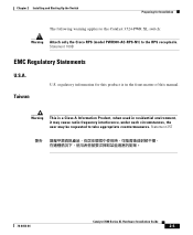
...at the speed of action. Caution It takes a Catalyst 3524-PWR XL 10/100 port up to 10 seconds to initially detect, power, and link to the status mode display, indicating that switch port. Call Cisco Systems immediately if your switch does not pass POST. Connecting devices that do not ...setting is connected. If the attached ports do not autonegotiate or that have their speed and duplex parameters manually set the speed and duplex parameters. Connecting to the 10/100 Ports The switch 10/100 Ethernet ports configure themselves to determine a course of attached devices. If a test fails,...
...at the speed of action. Caution It takes a Catalyst 3524-PWR XL 10/100 port up to 10 seconds to initially detect, power, and link to the status mode display, indicating that switch port. Call Cisco Systems immediately if your switch does not pass POST. Connecting devices that do not ...setting is connected. If the attached ports do not autonegotiate or that have their speed and duplex parameters manually set the speed and duplex parameters. Connecting to the 10/100 Ports The switch 10/100 Ethernet ports configure themselves to determine a course of attached devices. If a test fails,...
Installation Guide
Page 82
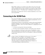
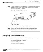
...the supplied rollover cable in the attached adapter. Figure 2-13 Connecting to the Console Port 32709 CONSOLE DC INPUTS FOR REMOTE POWER SUPPLY SPECIFIED IN MANUAL. +5V @24A, +12V @1.0A RJ-45 Console port Step 4 Step 5 Step 6 Rollover cable Attach the supplied RJ-45-to-DB... the terminal. Assigning Switch Information Chapter 2 Installing and Starting Up the Switch Step 3 Using the supplied rollover cable, insert the RJ-45 connector into the console port, as shown in the switch • Using a BOOTP server This section describes each method. 2-24 Catalyst 3500 Series XL Hardware...
...the supplied rollover cable in the attached adapter. Figure 2-13 Connecting to the Console Port 32709 CONSOLE DC INPUTS FOR REMOTE POWER SUPPLY SPECIFIED IN MANUAL. +5V @24A, +12V @1.0A RJ-45 Console port Step 4 Step 5 Step 6 Rollover cable Attach the supplied RJ-45-to-DB... the terminal. Assigning Switch Information Chapter 2 Installing and Starting Up the Switch Step 3 Using the supplied rollover cable, insert the RJ-45 connector into the console port, as shown in the switch • Using a BOOTP server This section describes each method. 2-24 Catalyst 3500 Series XL Hardware...

