Hardware Installation Guide
Page 19
... switches. A feature specific to the Catalyst 3524-PWR XL switch is its ability to provide inline power to Cisco IP Phones. (Phone adapters are not required when connecting to the Catalyst 3524-PWR XL 10/100 switch ports.) Figure 1-1 shows the switch models in different network topologies Features The Catalyst 3500 series XL switches-also referred to as Catalyst 3500 XL switches-are stackable 10/100 Ethernet switches...
... switches. A feature specific to the Catalyst 3524-PWR XL switch is its ability to provide inline power to Cisco IP Phones. (Phone adapters are not required when connecting to the Catalyst 3524-PWR XL 10/100 switch ports.) Figure 1-1 shows the switch models in different network topologies Features The Catalyst 3500 series XL switches-also referred to as Catalyst 3500 XL switches-are stackable 10/100 Ethernet switches...
Hardware Installation Guide
Page 23
... on AC input and supplies DC output to the Catalyst 3512, 3524, and 3548 XL switches • Connection for optional Cisco RPS 300 that operates on AC input and supplies DC output to the Catalyst 3524-PWR XL switch Inline Power (Catalyst 3524-PWR XL switch only) • Ability to provide inline power for Cisco IP Phones from all 24 10/100 Ethernet ports...
... on AC input and supplies DC output to the Catalyst 3512, 3524, and 3548 XL switches • Connection for optional Cisco RPS 300 that operates on AC input and supplies DC output to the Catalyst 3524-PWR XL switch Inline Power (Catalyst 3524-PWR XL switch only) • Ability to provide inline power for Cisco IP Phones from all 24 10/100 Ethernet ports...
Hardware Installation Guide
Page 24
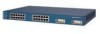
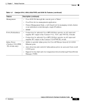
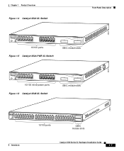
...Catalyst 3500 XL switches have a set of the Catalyst 3512, 3524, 3524-PWR and 3548 XL switches (Figure 1-3, Figure 1-4, Figure 1-5, and Figure 1-6) have 10/100 RJ-45 ports and two 1000BaseX GBIC module slots. Figure 1-2 Catalyst 3508G XL Switch 18966 1 SYSTEM RPS MODE STATUS UTIL DUPLX SPEED 2 3 4 5 6 7 8 GBIC module slots Figure 1-3 Catalyst 3512 XL Switch...10/100 ports 1 2 GBIC module slots 26235 Catalyst 3500 Series XL Hardware Installation Guide 1-6 78-6456-03 The front panel of LEDs and a Mode button. (The Catalyst 3548 XL switch has a Mode label that you press.) These front...
...Catalyst 3500 XL switches have a set of the Catalyst 3512, 3524, 3524-PWR and 3548 XL switches (Figure 1-3, Figure 1-4, Figure 1-5, and Figure 1-6) have 10/100 RJ-45 ports and two 1000BaseX GBIC module slots. Figure 1-2 Catalyst 3508G XL Switch 18966 1 SYSTEM RPS MODE STATUS UTIL DUPLX SPEED 2 3 4 5 6 7 8 GBIC module slots Figure 1-3 Catalyst 3512 XL Switch...10/100 ports 1 2 GBIC module slots 26235 Catalyst 3500 Series XL Hardware Installation Guide 1-6 78-6456-03 The front panel of LEDs and a Mode button. (The Catalyst 3548 XL switch has a Mode label that you press.) These front...
Hardware Installation Guide
Page 25
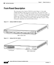
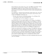
Chapter 1 Product Overview Figure 1-4 Catalyst 3524 XL Switch Front-Panel Description 26237 12 1X 34 56 78 MODE SYSTEM RPS STATUS 2X UTIL DUPLX SPEED 9 10 11 12 11X 12X 13 14 13X 15 16 17 18 19 20 21 22 23 24 23X 14X 24X 10/100 ports Figure 1-5 Catalyst 3524-PWR XL Switch 1 2 GBIC module slots 30291...
Chapter 1 Product Overview Figure 1-4 Catalyst 3524 XL Switch Front-Panel Description 26237 12 1X 34 56 78 MODE SYSTEM RPS STATUS 2X UTIL DUPLX SPEED 9 10 11 12 11X 12X 13 14 13X 15 16 17 18 19 20 21 22 23 24 23X 14X 24X 10/100 ports Figure 1-5 Catalyst 3524-PWR XL Switch 1 2 GBIC module slots 30291...

Hardware Installation Guide
Page 26
...10BaseT-compatible devices such as workstations, Cisco IP Phones, and hubs through standard RJ-45 connectors and Category 3, 4, or 5 cabling • 100BaseTX-compatible devices such as high-speed workstations, Cisco IP Phones, servers, hubs, routers, and other switches through , twisted-pair cable. If...speed that the cable is above port 4, and so on the Catalyst 3512, 3524, 3524-PWR, and 3548 XL switches are grouped in Appendix B, "Connector and Cable Specifications." Ports operating at 100 Mbps. When connecting the switch to any combination of half duplex, full duplex, 10 Mbps,...
...10BaseT-compatible devices such as workstations, Cisco IP Phones, and hubs through standard RJ-45 connectors and Category 3, 4, or 5 cabling • 100BaseTX-compatible devices such as high-speed workstations, Cisco IP Phones, servers, hubs, routers, and other switches through , twisted-pair cable. If...speed that the cable is above port 4, and so on the Catalyst 3512, 3524, 3524-PWR, and 3548 XL switches are grouped in Appendix B, "Connector and Cable Specifications." Ports operating at 100 Mbps. When connecting the switch to any combination of half duplex, full duplex, 10 Mbps,...
Hardware Installation Guide
Page 27
...Catalyst 3548 and 3524-PWR XL switches also support per -port basis, you can control whether or not a Catalyst 3524-PWR XL 10/100 port automatically provides power when a Cisco IP Phone is connected On a per -port priority override. However, the Catalyst 3524-PWR XL 10/100 ports can connect the Cisco IP Phone to a Catalyst 3524-PWR XL...power on the Catalyst 3512, 3524, 3524-PWR, and 3548 XL switches provide protocol support for inline power on the Catalyst 3512, 3524, and 3548 XL switches-must be connected to the Cisco IP Phone. When you select the Never setting for Cisco IP Phones. If...
...Catalyst 3548 and 3524-PWR XL switches also support per -port basis, you can control whether or not a Catalyst 3524-PWR XL 10/100 port automatically provides power when a Cisco IP Phone is connected On a per -port priority override. However, the Catalyst 3524-PWR XL 10/100 ports can connect the Cisco IP Phone to a Catalyst 3524-PWR XL...power on the Catalyst 3512, 3524, 3524-PWR, and 3548 XL switches provide protocol support for inline power on the Catalyst 3512, 3524, and 3548 XL switches-must be connected to the Cisco IP Phone. When you select the Never setting for Cisco IP Phones. If...
Hardware Installation Guide
Page 28
...a stack configuration) to eight GBICs in the Catalyst 3508G XL switch. Refer to the documentation that came with your GBIC module for a GigaStack GBIC-to nine Catalyst 3500 XL switches. Front-Panel Description Chapter 1 Product Overview GBIC Module Slots The Cisco Gigabit Interface Converter (GBIC) module slots support the...creating a 1-Gbps stack configuration of up to -GigaStack GBIC connection is inserted into a GBIC module slot on these switches, but you can install up to two GBICs in the Catalyst 3512, 3524, 3524-PWR and 3548 XL switches and up to other Gigabit Ethernet devices.
...a stack configuration) to eight GBICs in the Catalyst 3508G XL switch. Refer to the documentation that came with your GBIC module for a GigaStack GBIC-to nine Catalyst 3500 XL switches. Front-Panel Description Chapter 1 Product Overview GBIC Module Slots The Cisco Gigabit Interface Converter (GBIC) module slots support the...creating a 1-Gbps stack configuration of up to -GigaStack GBIC connection is inserted into a GBIC module slot on these switches, but you can install up to two GBICs in the Catalyst 3512, 3524, 3524-PWR and 3548 XL switches and up to other Gigabit Ethernet devices.
Hardware Installation Guide
Page 34
... RPS is not installed. Table 1-4 and Table 1-5 list the LED colors and their meanings. Note The Cisco RPS 600 (model PWR600-AC-RPS) supports the Catalyst 3512, 3524, 3548, and 3508 XL switches. If the switch power supply fails, the switch powers down , or a fan on the bottom of the power supplies in the RPS could have...
... RPS is not installed. Table 1-4 and Table 1-5 list the LED colors and their meanings. Note The Cisco RPS 600 (model PWR600-AC-RPS) supports the Catalyst 3512, 3524, 3548, and 3508 XL switches. If the switch power supply fails, the switch powers down , or a fan on the bottom of the power supplies in the RPS could have...
Hardware Installation Guide
Page 35
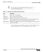
...-Panel Description Note The Cisco RPS 300 (model PWR300-AC-RPS) supports the Catalyst 3524-PWR XL switch. RPS is lost. The switch is backing up another switch in the RPS could have failed. RPS is operating on the Cisco RPS 300, refer to the Cisco Redundant Power System 300... Hardware Installation Guide. 78-6456-03 Catalyst 3500 Series XL Hardware Installation ...
...-Panel Description Note The Cisco RPS 300 (model PWR300-AC-RPS) supports the Catalyst 3524-PWR XL switch. RPS is lost. The switch is backing up another switch in the RPS could have failed. RPS is operating on the Cisco RPS 300, refer to the Cisco Redundant Power System 300... Hardware Installation Guide. 78-6456-03 Catalyst 3500 Series XL Hardware Installation ...
Hardware Installation Guide
Page 37
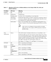
Port is operating at 1000 Mbps. 78-6456-03 Catalyst 3500 Series XL Hardware Installation Guide 1-19 Note After a port is reconfigured, the port LED can affect connectivity, and errors such as STP checks the switch for possible loops. If the LED to 30 seconds as excessive collisions,...SPEED (speed) Green Off Green 10/100 ports Off Green 1000BaseX ports Off Green The LEDs display backplane utilization on the Catalyst 3508, 3512, 3524, and 3548 XL Switches Port Mode STATUS (port status) LED Color Off Solid green Flashing green Alternating green-amber Solid amber Meaning No link. ...
Port is operating at 1000 Mbps. 78-6456-03 Catalyst 3500 Series XL Hardware Installation Guide 1-19 Note After a port is reconfigured, the port LED can affect connectivity, and errors such as STP checks the switch for possible loops. If the LED to 30 seconds as excessive collisions,...SPEED (speed) Green Off Green 10/100 ports Off Green 1000BaseX ports Off Green The LEDs display backplane utilization on the Catalyst 3508, 3512, 3524, and 3548 XL Switches Port Mode STATUS (port status) LED Color Off Solid green Flashing green Alternating green-amber Solid amber Meaning No link. ...
Hardware Installation Guide
Page 38
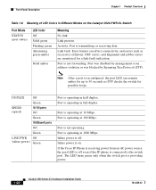
...is operating at 100 Mbps. The LED turns green only when the switch port is not forwarding. Port is providing power. 1-20 Catalyst 3500 Series XL Hardware Installation Guide 78-6456-03 Port is on the Catalyst 3524-PWR XL Switch Port Mode STATUS (port status) LED Color Off Solid green Flashing ... or receiving data. If the Cisco IP Phone is receiving power from an AC power source, the port LED is connected to 30 seconds as excessive collisions, CRC errors, and alignment and jabber errors are monitored for up to the switch port. Error frames can remain amber...
...is operating at 100 Mbps. The LED turns green only when the switch port is not forwarding. Port is providing power. 1-20 Catalyst 3500 Series XL Hardware Installation Guide 78-6456-03 Port is on the Catalyst 3524-PWR XL Switch Port Mode STATUS (port status) LED Color Off Solid green Flashing ... or receiving data. If the Cisco IP Phone is receiving power from an AC power source, the port LED is connected to 30 seconds as excessive collisions, CRC errors, and alignment and jabber errors are monitored for up to the switch port. Error frames can remain amber...
Hardware Installation Guide
Page 39
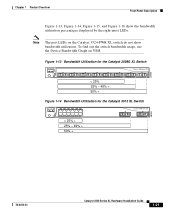
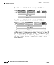
... usage, use the Device Bandwidth Graph on the Catalyst 3524-PWR XL switch do not show bandwidth utilization. Figure 1-13 Bandwidth Utilization for the Catalyst 3508G XL Switch 1 MODE SYSTEM RPS STATUS UTIL DUPLX SPEED 2 3 4 5 Catalyst 3500 XL 6 7 8 < 25% 25% - 49% + 50% + Figure 1-14 Bandwidth Utilization for the Catalyst 3512 XL Switch MODE SYSTEM RPS STATUS UTIL DUPLX SPEED 12 1X 34...
... usage, use the Device Bandwidth Graph on the Catalyst 3524-PWR XL switch do not show bandwidth utilization. Figure 1-13 Bandwidth Utilization for the Catalyst 3508G XL Switch 1 MODE SYSTEM RPS STATUS UTIL DUPLX SPEED 2 3 4 5 Catalyst 3500 XL 6 7 8 < 25% 25% - 49% + 50% + Figure 1-14 Bandwidth Utilization for the Catalyst 3512 XL Switch MODE SYSTEM RPS STATUS UTIL DUPLX SPEED 12 1X 34...
Hardware Installation Guide
Page 40
... Installation Guide 78-6456-03 Front-Panel Description Chapter 1 Product Overview 22007 Figure 1-15 Bandwidth Utilization for the Catalyst 3524 XL Switch MODE SYSTEM RPS STATUS UTIL DUPLX SPEED 12 1X 34 56 78 9 10 11 12 11X 2X 12X 13 14 15 16 13X 17 18 ...19 20 21 22 23 24 15X 14X 16X < 25% + 25% - 49% + 50% + Catalyst 3500 XL 1 2 Figure 1-16 Bandwidth Utilization for the Catalyst 3548 XL Switch 28366 SYSTEM RPS STATUS UTIL DUPLX SPEED MODE 12 1X 3 24 56 78 9 10 11 12 13 14 15 16 15X...
... Installation Guide 78-6456-03 Front-Panel Description Chapter 1 Product Overview 22007 Figure 1-15 Bandwidth Utilization for the Catalyst 3524 XL Switch MODE SYSTEM RPS STATUS UTIL DUPLX SPEED 12 1X 34 56 78 9 10 11 12 11X 2X 12X 13 14 15 16 13X 17 18 ...19 20 21 22 23 24 15X 14X 16X < 25% + 25% - 49% + 50% + Catalyst 3500 XL 1 2 Figure 1-16 Bandwidth Utilization for the Catalyst 3548 XL Switch 28366 SYSTEM RPS STATUS UTIL DUPLX SPEED MODE 12 1X 3 24 56 78 9 10 11 12 13 14 15 16 15X...
Hardware Installation Guide
Page 41
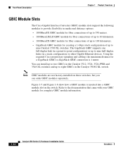
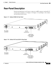
....T+E3P.3OVW***E@R1S4UAP, PLY DC INPUT +12V***@3A AC power connector RJ-45 console port Redundant power system connector Figure 1-18 Catalyst 3512 and 3524 XL Rear Panel Fans 18964 RATING 100-127/200-240V~ 1.0A/0.5A 50-60HZ AC power connector 78-6456-03 CONSOLE DC INPUTS... MANUAL. +5V @24A, +12V @.5A RJ-45 console port Redundant power system connector Fans Catalyst 3500 Series XL Hardware Installation Guide 1-23 Chapter 1 Product Overview Rear-Panel Description Rear-Panel Description Switch rear panels have an AC power connector, an RPS connector, and an RJ-45 console port ...
....T+E3P.3OVW***E@R1S4UAP, PLY DC INPUT +12V***@3A AC power connector RJ-45 console port Redundant power system connector Figure 1-18 Catalyst 3512 and 3524 XL Rear Panel Fans 18964 RATING 100-127/200-240V~ 1.0A/0.5A 50-60HZ AC power connector 78-6456-03 CONSOLE DC INPUTS... MANUAL. +5V @24A, +12V @.5A RJ-45 console port Redundant power system connector Fans Catalyst 3500 Series XL Hardware Installation Guide 1-23 Chapter 1 Product Overview Rear-Panel Description Rear-Panel Description Switch rear panels have an AC power connector, an RPS connector, and an RJ-45 console port ...

Hardware Installation Guide
Page 43
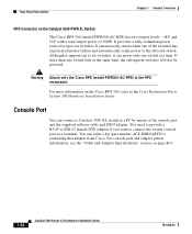
Cisco RPS Connector Specific Cisco RPS models support specific Catalyst 3500 XL switches: • Cisco RPS 600 (model PWR600-AC-RPS)-Supports the Catalyst 3512, 3524, 3548, and 3508 XL switches • Cisco RPS 300 (model PWR300-AC-RPS)-Supports the Catalyst 3524-PWR XL switch RPS Connector on the Catalyst 3508, 3512, 3524, and 3548 XL Switches The Cisco RPS 600 (model PWR600-AC-RPS) provides a quasi-redundant power source...
Cisco RPS Connector Specific Cisco RPS models support specific Catalyst 3500 XL switches: • Cisco RPS 600 (model PWR600-AC-RPS)-Supports the Catalyst 3512, 3524, 3548, and 3508 XL switches • Cisco RPS 300 (model PWR300-AC-RPS)-Supports the Catalyst 3524-PWR XL switch RPS Connector on the Catalyst 3508, 3512, 3524, and 3548 XL Switches The Cisco RPS 600 (model PWR600-AC-RPS) provides a quasi-redundant power source...
Hardware Installation Guide
Page 44
..., see the "Cable and Adapter Specifications" section on page B-4. 1-26 Catalyst 3500 Series XL Hardware Installation Guide 78-6456-03 Rear-Panel Description Chapter 1 Product Overview RPS Connector on the Catalyst 3524-PWR XL Switch The Cisco RPS 300 (model PWR300-AC-RPS) has two output levels: -48V ...and 12V with a total output power of the switches has experienced power failure and automatically sends power to the affected switch. You need to provide a...
..., see the "Cable and Adapter Specifications" section on page B-4. 1-26 Catalyst 3500 Series XL Hardware Installation Guide 78-6456-03 Rear-Panel Description Chapter 1 Product Overview RPS Connector on the Catalyst 3524-PWR XL Switch The Cisco RPS 300 (model PWR300-AC-RPS) has two output levels: -48V ...and 12V with a total output power of the switches has experienced power failure and automatically sends power to the affected switch. You need to provide a...
Hardware Installation Guide
Page 52
... serves as illustrated, or into multiple clusters, as a single point for 802.1p/Q QoS to give forwarding priority to switches other than the Catalyst 3524-PWR XL switches receive power from their PCs. Using the Cisco Cluster Management Suite, you can place, receive, and control calls from an AC power source. The gigabit connections to a server...
... serves as illustrated, or into multiple clusters, as a single point for 802.1p/Q QoS to give forwarding priority to switches other than the Catalyst 3524-PWR XL switches receive power from their PCs. Using the Cisco Cluster Management Suite, you can place, receive, and control calls from an AC power source. The gigabit connections to a server...

Hardware Installation Guide
Page 53
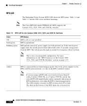
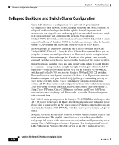
... in full duplex). Figure 1-23 Collapsed Backbone and Switch Cluster Configuration Gigabit servers Cisco CallManager Catalyst 4908G-L3 switch Cisco 2600 router 1 Gbps (2 Gbps full duplex) Catalyst 3500 XL and 2900 XL GigaStack cluster Catalyst 2900 XL, 1900, and 2820 cluster 200 Mbps Fast EtherChannel (400 Mbps full duplex Fast EtherChannel) Catalyst 3524-PWR XL GigaStack cluster IP IP AC power source Workstations...
... in full duplex). Figure 1-23 Collapsed Backbone and Switch Cluster Configuration Gigabit servers Cisco CallManager Catalyst 4908G-L3 switch Cisco 2600 router 1 Gbps (2 Gbps full duplex) Catalyst 3500 XL and 2900 XL GigaStack cluster Catalyst 2900 XL, 1900, and 2820 cluster 200 Mbps Fast EtherChannel (400 Mbps full duplex Fast EtherChannel) Catalyst 3524-PWR XL GigaStack cluster IP IP AC power source Workstations...
Hardware Installation Guide
Page 60
... 2-4 78-6456-03 Preparing for this product is in the front matter of lightning activity. The following warning applies to the Catalyst 3508, 3512, 3524, and 3548 XL switches: Warning Attach only the Cisco RPS (model PWR600-AC-RPS) to the RPS receptacle. Warning Ultimate disposal of this product should be handled according to the...
... 2-4 78-6456-03 Preparing for this product is in the front matter of lightning activity. The following warning applies to the Catalyst 3508, 3512, 3524, and 3548 XL switches: Warning Attach only the Cisco RPS (model PWR600-AC-RPS) to the RPS receptacle. Warning Ultimate disposal of this product should be handled according to the...
Hardware Installation Guide
Page 91
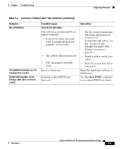
... indicated by no link at both ends: • A crossover cable was used when a straight-through cables, see which POST test failed. 78-6456-03 Catalyst 3500 Series XL Hardware Installation Guide 3-5 Nonfatal or fatal POST error detected. Possible Cause Incorrect or bad cable. Incorrect baud rate. Resolution • For the correct pinouts... for LED to 9600 baud. straight-through was required, or vice-versa. • The cable is amber on the management console. Unreadable characters on the Catalyst 3508, 3512, or 3524 XL switch. Reset the emulation software to turn green.
... indicated by no link at both ends: • A crossover cable was used when a straight-through cables, see which POST test failed. 78-6456-03 Catalyst 3500 Series XL Hardware Installation Guide 3-5 Nonfatal or fatal POST error detected. Possible Cause Incorrect or bad cable. Incorrect baud rate. Resolution • For the correct pinouts... for LED to 9600 baud. straight-through was required, or vice-versa. • The cable is amber on the management console. Unreadable characters on the Catalyst 3508, 3512, or 3524 XL switch. Reset the emulation software to turn green.


