
Hardware Installation Guide
Page 3
... ix Audience ix Purpose ix Conventions ix Related Publications xv Obtaining Documentation xvii Cisco.com xvii Documentation CD-ROM xvii Ordering Documentation xvii Documentation Feedback xviii Obtaining Technical Assistance xviii Cisco TAC Website xviii Opening a TAC Case xviii TAC Case Priority Definitions xix .../100/1000 Ports 1-8 100BASE-FX and 1000BASE-SX Ports 1-9 LRE Port 1-9 GBIC Module Ports 1-10 SFP Module Slots 1-11 SFP Modules 1-11 LEDs 1-13 System LED 1-16 RPS LED 1-16 Port Mode and Port Status LEDs 1-16 CONTENTS OL-6156-01 Catalyst 2950 Switch Hardware Installation Guide iii
... ix Audience ix Purpose ix Conventions ix Related Publications xv Obtaining Documentation xvii Cisco.com xvii Documentation CD-ROM xvii Ordering Documentation xvii Documentation Feedback xviii Obtaining Technical Assistance xviii Cisco TAC Website xviii Opening a TAC Case xviii TAC Case Priority Definitions xix .../100/1000 Ports 1-8 100BASE-FX and 1000BASE-SX Ports 1-9 LRE Port 1-9 GBIC Module Ports 1-10 SFP Module Slots 1-11 SFP Modules 1-11 LEDs 1-13 System LED 1-16 RPS LED 1-16 Port Mode and Port Status LEDs 1-16 CONTENTS OL-6156-01 Catalyst 2950 Switch Hardware Installation Guide iii
Hardware Installation Guide
Page 4
...1-23 Cisco RPS Connector 1-23 Console Port 1-24 Management Options 1-24 Installation 2-1 Preparing for Installation 2-1 Warnings 2-1 Installation Guidelines 2-4 Verifying Package Contents 2-5 Verifying Switch Operation 2-6 Installing the Switch 2-7 Installing the Switch in a Rack 2-7 Attaching the Brackets to the Switch 2-8 Mounting the Switch in...the Switch to a Wall 2-18 Installing the Optional AC Ground Kit for Catalyst 2950 Switches 2-19 Installing the GBIC Modules 2-22 Installing and Removing SFP Modules 2-23 Installing SFP Modules into SFP Module Slots 2-23 Removing SFP Modules from SFP ...
...1-23 Cisco RPS Connector 1-23 Console Port 1-24 Management Options 1-24 Installation 2-1 Preparing for Installation 2-1 Warnings 2-1 Installation Guidelines 2-4 Verifying Package Contents 2-5 Verifying Switch Operation 2-6 Installing the Switch 2-7 Installing the Switch in a Rack 2-7 Attaching the Brackets to the Switch 2-8 Mounting the Switch in...the Switch to a Wall 2-18 Installing the Optional AC Ground Kit for Catalyst 2950 Switches 2-19 Installing the GBIC Modules 2-22 Installing and Removing SFP Modules 2-23 Installing SFP Modules into SFP Module Slots 2-23 Removing SFP Modules from SFP ...

Hardware Installation Guide
Page 5
...to 1000BASE-T GBIC Module Ports 2-36 Connecting to GigaStack GBIC Module Ports 2-37 Connecting to SFP Modules 2-38 Connecting to Fiber-Optic SFP Modules 2-38 Connecting to 1000BASE-T SFP Modules 2-39 Where to Go Next 2-40 Troubleshooting 3-1 Understanding POST Results 3-1 Diagnosing Problems ...Port B-3 100BASE-FX and 1000BASE-SX Ports B-4 1000BASE-X GBIC Module Ports B-4 1000BASE-T GBIC Module Ports B-4 GigaStack GBIC Module Ports B-4 SFP Module Ports B-5 Console Port B-5 Identifying a Crossover Cable B-5 Cable and Adapter Specifications B-6 Two Twisted-Pair Cable Pinouts B-6 Four Twisted-Pair ...
...to 1000BASE-T GBIC Module Ports 2-36 Connecting to GigaStack GBIC Module Ports 2-37 Connecting to SFP Modules 2-38 Connecting to Fiber-Optic SFP Modules 2-38 Connecting to 1000BASE-T SFP Modules 2-39 Where to Go Next 2-40 Troubleshooting 3-1 Understanding POST Results 3-1 Diagnosing Problems ...Port B-3 100BASE-FX and 1000BASE-SX Ports B-4 1000BASE-X GBIC Module Ports B-4 1000BASE-T GBIC Module Ports B-4 GigaStack GBIC Module Ports B-4 SFP Module Ports B-5 Console Port B-5 Identifying a Crossover Cable B-5 Cable and Adapter Specifications B-6 Two Twisted-Pair Cable Pinouts B-6 Four Twisted-Pair ...

Hardware Installation Guide
Page 22
...Catalyst 2950ST-24 LRE switch-24 LRE ports, 2 10/100/1000 Ethernet ports, and 2 SFP module slots. (Two of the four uplink ports are active at one time.) Note See the Catalyst 2950 LRE switch release notes for a list of supported SFP modules for the Catalyst 2950 LRE switches. - Catalyst 2950ST-24 LRE 997 switch-24...- Features Chapter 1 Overview - Catalyst 2950SX-24 switch-24 10/100 Ethernet ports and 2 1000BASE-SX ports - On Catalyst 2950G-12-EI, 2950G-24-EI, 2950G-24-EI-DC, and 2950G-48-EI switches, support for errors on the Catalyst 2950T-24 switch, autonegotiates the speed and supports ...
...Catalyst 2950ST-24 LRE switch-24 LRE ports, 2 10/100/1000 Ethernet ports, and 2 SFP module slots. (Two of the four uplink ports are active at one time.) Note See the Catalyst 2950 LRE switch release notes for a list of supported SFP modules for the Catalyst 2950 LRE switches. - Catalyst 2950ST-24 LRE 997 switch-24...- Features Chapter 1 Overview - Catalyst 2950SX-24 switch-24 10/100 Ethernet ports and 2 1000BASE-SX ports - On Catalyst 2950G-12-EI, 2950G-24-EI, 2950G-24-EI-DC, and 2950G-48-EI switches, support for errors on the Catalyst 2950T-24 switch, autonegotiates the speed and supports ...
Hardware Installation Guide
Page 25
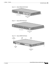
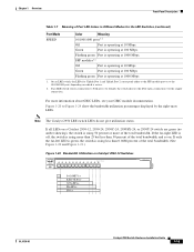
... 8 9 10 11 12 11X 2X 12X 13X 13 14 15 16 17 18 19 20 21 22 23 24 23X 14X 24X 10/100 ports 1 Catalyst 2950 SERIES 2 GBIC module slots Figure 1-7 Catalyst 2950G-48-EI Switch SYST RPS STAT UTIL DUPLX SPEED MODE 1 1X 2X 23 45 67 8 9 10 11 12 13 14... 22 23 24 25 26 27 28 29 30 31 32 16X 18X 33 31X 33X 34 35 36 37 38 39 40 41 42 43 44 45 46 47 48 47X 32X 34X 48X 10/100 ports Catalyst 2950 SERIES 1 2 GBIC module slots Figure 1-8 Catalyst 2950ST-8 LRE Switch Power LRE connector port SFP ports...
... 8 9 10 11 12 11X 2X 12X 13X 13 14 15 16 17 18 19 20 21 22 23 24 23X 14X 24X 10/100 ports 1 Catalyst 2950 SERIES 2 GBIC module slots Figure 1-7 Catalyst 2950G-48-EI Switch SYST RPS STAT UTIL DUPLX SPEED MODE 1 1X 2X 23 45 67 8 9 10 11 12 13 14... 22 23 24 25 26 27 28 29 30 31 32 16X 18X 33 31X 33X 34 35 36 37 38 39 40 41 42 43 44 45 46 47 48 47X 32X 34X 48X 10/100 ports Catalyst 2950 SERIES 1 2 GBIC module slots Figure 1-8 Catalyst 2950ST-8 LRE Switch Power LRE connector port SFP ports...
Hardware Installation Guide
Page 26
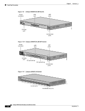
...14 15 16 17 18 19 20 21 22 23 24 Catalyst 2950 SERIES LRE 1 2 1 2 10/100/1000 ports Figure 1-10 Catalyst 2950ST-24 LRE 997 Switch Power connector LRE port SFP ports - ++ A INPCUUTR:RE3N6T- B 72 V ...:2-1 A - SYST RPS STAT SPEED MODE CONSOLE 1 2 3 4 5 6 7 8 9 10 11 12 Console port DC ground lug 13 14 15 16 17 18 19 20 21 22 23 24 Catalyst 2950 SERIES LRE 997 1 2 1 2 DC ground lug 10/100/1000 ports Figure 1-11 Catalyst 2950SX-24 Switch...
...14 15 16 17 18 19 20 21 22 23 24 Catalyst 2950 SERIES LRE 1 2 1 2 10/100/1000 ports Figure 1-10 Catalyst 2950ST-24 LRE 997 Switch Power connector LRE port SFP ports - ++ A INPCUUTR:RE3N6T- B 72 V ...:2-1 A - SYST RPS STAT SPEED MODE CONSOLE 1 2 3 4 5 6 7 8 9 10 11 12 Console port DC ground lug 13 14 15 16 17 18 19 20 21 22 23 24 Catalyst 2950 SERIES LRE 997 1 2 1 2 DC ground lug 10/100/1000 ports Figure 1-11 Catalyst 2950SX-24 Switch...
Hardware Installation Guide
Page 29
...24 Cisco LRE CPE devices through structured or unstructured wiring, such as LRE traffic, the LRE port must be used. The splitter routes LRE data (high-frequency) and voice (low-frequency) traffic from a 100BASE-FX port on the same Catalyst 2950ST-8 LRE or 2950ST-24 LRE switch. See the "SFP ...Module Slots" section on page 1-11 for each consisting of up to the patch panel through a PBX switch, a non-homologated POTS splitter, such as two logical ports, each...
...24 Cisco LRE CPE devices through structured or unstructured wiring, such as LRE traffic, the LRE port must be used. The splitter routes LRE data (high-frequency) and voice (low-frequency) traffic from a 100BASE-FX port on the same Catalyst 2950ST-8 LRE or 2950ST-24 LRE switch. See the "SFP ...Module Slots" section on page 1-11 for each consisting of up to the patch panel through a PBX switch, a non-homologated POTS splitter, such as two logical ports, each...

Hardware Installation Guide
Page 31
...-length specifications on Uplink Port 1. These transceiver modules are up to 1000BASE-T SFP modules. When determining where to place the switch, be connecting to both, in the Catalyst 2950 LRE switch release notes. For example, you connect to the fiber-optic port on Uplink... fiber-optic SFP module connections. You use Ethernet SFP modules to establish uplink connections to fiber-optic SFP modules. Chapter 1 Overview Front-Panel Description SFP Module Slots On the Catalyst 2950 LRE switch, the SFP module slots support the SFP modules listed in default operation, the SFP module port...
...-length specifications on Uplink Port 1. These transceiver modules are up to 1000BASE-T SFP modules. When determining where to place the switch, be connecting to both, in the Catalyst 2950 LRE switch release notes. For example, you connect to the fiber-optic port on Uplink... fiber-optic SFP module connections. You use Ethernet SFP modules to establish uplink connections to fiber-optic SFP modules. Chapter 1 Overview Front-Panel Description SFP Module Slots On the Catalyst 2950 LRE switch, the SFP module slots support the SFP modules listed in default operation, the SFP module port...

Hardware Installation Guide
Page 32
... the interface in the link to 100 km)2 1. Using an ordinary patch cord with a Cisco-approved module. the distance depends on the Catalyst 2950 LRE switch. Use only Cisco-approved SFP modules on the fiber quality, the number of single-mode fiber cable, you are using dispersion-shifted SMF or low-attenuation SMF; For more...
... the interface in the link to 100 km)2 1. Using an ordinary patch cord with a Cisco-approved module. the distance depends on the Catalyst 2950 LRE switch. Use only Cisco-approved SFP modules on the fiber quality, the number of single-mode fiber cable, you are using dispersion-shifted SMF or low-attenuation SMF; For more...
Hardware Installation Guide
Page 39
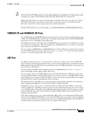
... all LEDs on a Catalyst 2950-12, 2950-24, 2950C-24, 2950SX-24, or 2950T-24 switch are green (no amber showing), the switch is using more than 25 but less than 0.0488 percent of the total bandwidth. (See Figure 1-20 and Figure 1-21.) Figure 1-20 Bandwidth Utilization on Catalyst 2950-12 Switches SYST RPS STAT UTIL ... depending on which is active. 2. Green Port is operating at 100 Mbps. Figure 1-20 to both ports, by the right-most LEDs. SFP modules1 2 Off Port is operating at 10 Mbps Green Port is operating at 100 Mbps Flashing green Port is operating at 1000 Mbps 1. If...
... all LEDs on a Catalyst 2950-12, 2950-24, 2950C-24, 2950SX-24, or 2950T-24 switch are green (no amber showing), the switch is using more than 25 but less than 0.0488 percent of the total bandwidth. (See Figure 1-20 and Figure 1-21.) Figure 1-20 Bandwidth Utilization on Catalyst 2950-12 Switches SYST RPS STAT UTIL ... depending on which is active. 2. Green Port is operating at 100 Mbps. Figure 1-20 to both ports, by the right-most LEDs. SFP modules1 2 Off Port is operating at 10 Mbps Green Port is operating at 100 Mbps Flashing green Port is operating at 1000 Mbps 1. If...

Hardware Installation Guide
Page 47
... Port, page 2-30 • Connecting to GBIC Module Ports, page 2-35 • Connecting to SFP Modules, page 2-38 • Where to the RPS receptacle. Warning Attach only the Cisco Redundant Power Supply (RPS) (model PWR300-AC-RPS-N1) to Go Next, page 2-40 Preparing ...Contents, page 2-5 Warnings For translations of these warnings in several languages, see the Regulatory Compliance and Safety Information for the Catalyst 2950 Switch. Statement 100B OL-6156-01 Catalyst 2950 Switch Hardware Installation Guide 2-1 Installation CH A P T E R 2 This chapter describes how to install your...
... Port, page 2-30 • Connecting to GBIC Module Ports, page 2-35 • Connecting to SFP Modules, page 2-38 • Where to the RPS receptacle. Warning Attach only the Cisco Redundant Power Supply (RPS) (model PWR300-AC-RPS-N1) to Go Next, page 2-40 Preparing ...Contents, page 2-5 Warnings For translations of these warnings in several languages, see the Regulatory Compliance and Safety Information for the Catalyst 2950 Switch. Statement 100B OL-6156-01 Catalyst 2950 Switch Hardware Installation Guide 2-1 Installation CH A P T E R 2 This chapter describes how to install your...
Hardware Installation Guide
Page 69
... that is absolutely necessary. You can shorten its useful life. Each SFP module has an internal serial EEPROM that has a bale-clasp latch. Refer to identify and validate that the Catalyst 2950 LRE switch supports. This encoding provides a way for Cisco to Table 1-2 for cable stipulations for reliable communications, the cable must not exceed...
... that is absolutely necessary. You can shorten its useful life. Each SFP module has an internal serial EEPROM that has a bale-clasp latch. Refer to identify and validate that the Catalyst 2950 LRE switch supports. This encoding provides a way for Cisco to Table 1-2 for cable stipulations for reliable communications, the cable must not exceed...

Hardware Installation Guide
Page 70
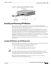
...(TX or RX). Note On some SFP modules, the send and receive (TX and RX) markings might be replaced by arrows that identify the top side of the SFP module. Step 3 Step 4 Align the SFP module in the rear of the slot. 2-24 Catalyst 2950 Switch Hardware Installation Guide OL-6156-01 Insert... the SFP module into the slot until you feel the connector on the module snap ...
...(TX or RX). Note On some SFP modules, the send and receive (TX and RX) markings might be replaced by arrows that identify the top side of the SFP module. Step 3 Step 4 Align the SFP module in the rear of the slot. 2-24 Catalyst 2950 Switch Hardware Installation Guide OL-6156-01 Insert... the SFP module into the slot until you feel the connector on the module snap ...

Hardware Installation Guide
Page 71
... parallel direction. Step 3 Step 4 For fiber-optic SFP modules, insert a dust plug into an SFP Module Slot 19 20 21 22 23 24 Catalyst 2950 LRE SERIES 1 2 1 2 81564 Step 5 For fiber-optic SFP modules, remove the dust plugs from the SFP module optical ports and store them for later use a ...or MT-RJ cable connector into the SFP module. • For copper SFP modules, insert the RJ-45 cable connector into the SFP module. OL-6156-01 Catalyst 2950 Switch Hardware Installation Guide 2-25 Removing SFP Modules from SFP Module Slots To remove an SFP module from the fiber-optic cable until ...
... parallel direction. Step 3 Step 4 For fiber-optic SFP modules, insert a dust plug into an SFP Module Slot 19 20 21 22 23 24 Catalyst 2950 LRE SERIES 1 2 1 2 81564 Step 5 For fiber-optic SFP modules, remove the dust plugs from the SFP module optical ports and store them for later use a ...or MT-RJ cable connector into the SFP module. • For copper SFP modules, insert the RJ-45 cable connector into the SFP module. OL-6156-01 Catalyst 2950 Switch Hardware Installation Guide 2-25 Removing SFP Modules from SFP Module Slots To remove an SFP module from the fiber-optic cable until ...

Hardware Installation Guide
Page 72
...a small, flat-blade screwdriver or other protective environment. 2-26 Catalyst 2950 Switch Hardware Installation Guide OL-6156-01 Installing and Removing SFP Modules Chapter 2 Installation Figure 2-32 Using the Mylar Tab Latch to Remove an SFP Module from a Slot 19 20 21 22 23 24 Catalyst 2950 SERIES LRE 1 2 1 2 81565 • If the... to grip the ridge on the wedge to free the locking pin, and use your index finger to open it from an SFP Module Slot 19 20 21 22 23 24 Catalyst 2950 SERIES LRE 1 2 1 2 81566 • If the module has a bale-clasp latch, pull the bale out and ...
...a small, flat-blade screwdriver or other protective environment. 2-26 Catalyst 2950 Switch Hardware Installation Guide OL-6156-01 Installing and Removing SFP Modules Chapter 2 Installation Figure 2-32 Using the Mylar Tab Latch to Remove an SFP Module from a Slot 19 20 21 22 23 24 Catalyst 2950 SERIES LRE 1 2 1 2 81565 • If the... to grip the ridge on the wedge to free the locking pin, and use your index finger to open it from an SFP Module Slot 19 20 21 22 23 24 Catalyst 2950 SERIES LRE 1 2 1 2 81566 • If the module has a bale-clasp latch, pull the bale out and ...
Hardware Installation Guide
Page 73
... in full-duplex mode. Within each consisting of the connection. Caution The Catalyst 2950G-24-EI-DC or Catalyst 2950ST-24 LRE 997 switch is suitable only for both ends of a copper 10/100/1000 port and a fiber-optic SFP module slot, respectively. See the "SFP Module Slots" section on page 1-11 for more than two connections...
... in full-duplex mode. Within each consisting of the connection. Caution The Catalyst 2950G-24-EI-DC or Catalyst 2950ST-24 LRE 997 switch is suitable only for both ends of a copper 10/100/1000 port and a fiber-optic SFP module slot, respectively. See the "SFP Module Slots" section on page 1-11 for more than two connections...

Hardware Installation Guide
Page 84
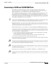
...in the target device. Note See the Catalyst 2950 LRE release notes for loops. Connecting to Fiber-Optic SFP Modules Follow these steps to connect a fiber-optic cable to an SFP module: Caution Do not remove the rubber plugs from the SFP module port or the rubber caps from ... Chapter 3, "Troubleshooting," for future use. Insert the other cable end into the SFP module port (see the "Installing and Removing SFP Modules" section on fiber-optic SFP modules. The LED turns green when the switch and the target device have an established link. For instructions about 30 seconds, and...
...in the target device. Note See the Catalyst 2950 LRE release notes for loops. Connecting to Fiber-Optic SFP Modules Follow these steps to connect a fiber-optic cable to an SFP module: Caution Do not remove the rubber plugs from the SFP module port or the rubber caps from ... Chapter 3, "Troubleshooting," for future use. Insert the other cable end into the SFP module port (see the "Installing and Removing SFP Modules" section on fiber-optic SFP modules. The LED turns green when the switch and the target device have an established link. For instructions about 30 seconds, and...

Hardware Installation Guide
Page 85
... normal board and component handling procedures. The LED turns green when the switch and the target device have an established link. OL-6156-01 Catalyst 2950 Switch Hardware Installation Guide 2-39 Figure 2-44 Connecting to a 1000BASE-T SFP Module 19 20 21 22 23 24 Catalyst 2950 SERIES LRE 1 2 1 2 97631 RJ-45 cable Step 2 Step 3 Insert the...
... normal board and component handling procedures. The LED turns green when the switch and the target device have an established link. OL-6156-01 Catalyst 2950 Switch Hardware Installation Guide 2-39 Figure 2-44 Connecting to a 1000BASE-T SFP Module 19 20 21 22 23 24 Catalyst 2950 SERIES LRE 1 2 1 2 97631 RJ-45 cable Step 2 Step 3 Insert the...

Hardware Installation Guide
Page 88
... port and the attached device exceeds 328 feet (100 meters). • Reduce cable length to your repeater documentation for SFP cabling guidelines. STP2 checking for port status LED to turn green. Catalyst 2950 Switch Hardware Installation Guide 3-2 OL-6156-01 Diagnosing Problems Chapter 3 Troubleshooting Table 3-1 Common Problems and Solutions Symptom Poor performance or...
... port and the attached device exceeds 328 feet (100 meters). • Reduce cable length to your repeater documentation for SFP cabling guidelines. STP2 checking for port status LED to turn green. Catalyst 2950 Switch Hardware Installation Guide 3-2 OL-6156-01 Diagnosing Problems Chapter 3 Troubleshooting Table 3-1 Common Problems and Solutions Symptom Poor performance or...

Hardware Installation Guide
Page 89
Switch not recognizing a GBIC module. Refer to your GBIC module documentation for possible loops. For more information. If the fan has failed, call Cisco Systems. • Use the show env fan privileged EXEC command. Unreadable characters on page B-6. • ...LED is amber. Reset the terminal-emulation software to turn green. Switch not recognizing an SFP module. Refer to your SFP module documentation for port status LED to 9600 baud. OL-6156-01 Catalyst 2950 Switch Hardware Installation Guide 3-3 Chapter 3 Troubleshooting Diagnosing Problems Table 3-1 Common...
Switch not recognizing a GBIC module. Refer to your GBIC module documentation for possible loops. For more information. If the fan has failed, call Cisco Systems. • Use the show env fan privileged EXEC command. Unreadable characters on page B-6. • ...LED is amber. Reset the terminal-emulation software to turn green. Switch not recognizing an SFP module. Refer to your SFP module documentation for port status LED to 9600 baud. OL-6156-01 Catalyst 2950 Switch Hardware Installation Guide 3-3 Chapter 3 Troubleshooting Diagnosing Problems Table 3-1 Common...
