
Hardware Installation Guide
Page 8
... In the event of a discontinuance of product manufacture, the Cisco warranty support is limited to five (5) years. Company product purchased from Cisco, contact your Cisco Sales and Service Representative. Replacement, Repair, or Refund Policy for Hardware Cisco or its service center will use the product, provided that ... you purchased the product directly from Company telephone number Product model number Product serial number Maintenance contract number Catalyst 2950 Switch Hardware Installation Guide viii OL-6156-01 Actual delivery times can vary, depending on the customer location.
... In the event of a discontinuance of product manufacture, the Cisco warranty support is limited to five (5) years. Company product purchased from Cisco, contact your Cisco Sales and Service Representative. Replacement, Repair, or Refund Policy for Hardware Cisco or its service center will use the product, provided that ... you purchased the product directly from Company telephone number Product model number Product serial number Maintenance contract number Catalyst 2950 Switch Hardware Installation Guide viii OL-6156-01 Actual delivery times can vary, depending on the customer location.

Hardware Installation Guide
Page 30
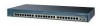
Front-Panel Description Chapter 1 Overview For limitations and restrictions when you are using a non-Cisco approved CWDM GBIC module, remove the module from the switch, and replace it with POTS Splitters" section on page 2-31. For more information about these modules: • 1000BASE.... Note If you use a POTS splitter with the Catalyst 2950 LRE switches and Cisco LRE CPE, see the "Limitations and Restrictions with a Cisco-approved module. For more information about the Cisco LRE CPE devices, see your Cisco sales representative. GBIC Module Ports The GBIC module slots support...
Front-Panel Description Chapter 1 Overview For limitations and restrictions when you are using a non-Cisco approved CWDM GBIC module, remove the module from the switch, and replace it with POTS Splitters" section on page 2-31. For more information about these modules: • 1000BASE.... Note If you use a POTS splitter with the Catalyst 2950 LRE switches and Cisco LRE CPE, see the "Limitations and Restrictions with a Cisco-approved module. For more information about the Cisco LRE CPE devices, see your Cisco sales representative. GBIC Module Ports The GBIC module slots support...

Hardware Installation Guide
Page 31
...front of supported SFP modules. The SFP modules support nominal wavelengths from the switch to connected devices are inserted into SFP module slots on the front panel and are field-replaceable. OL-6156-01 Catalyst 2950 Switch Hardware Installation Guide 1-11 Note By using the media-type {sfp | rj45... Ethernet SFP modules to establish uplink connections to either the SFP module port or the 10/100/1000 port. See the Catalyst 2950 LRE switch release notes for reliable communications, the cable must match the wave-length specifications on the other . For example, you can...
...front of supported SFP modules. The SFP modules support nominal wavelengths from the switch to connected devices are inserted into SFP module slots on the front panel and are field-replaceable. OL-6156-01 Catalyst 2950 Switch Hardware Installation Guide 1-11 Note By using the media-type {sfp | rj45... Ethernet SFP modules to establish uplink connections to either the SFP module port or the 10/100/1000 port. See the Catalyst 2950 LRE switch release notes for reliable communications, the cable must match the wave-length specifications on the other . For example, you can...

Hardware Installation Guide
Page 32
... documentation. 1-12 Catalyst 2950 Switch Hardware Installation Guide OL-6156-01 If the serial number, the vendor name or ID, security code, or CRC is required. Note When using a non-Cisco approved SFP module, remove the module from the switch, and replace it with MMF,... overloading the receiver. A mode-conditioning patch cord is invalid, the switch places the interface in the switch, the switch software reads the EEPROM to 100 km)2 1. the distance depends on the Catalyst 2950 LRE switch. Front-Panel Description Chapter 1 Overview Table 1-2 Fiber-Optic SFP Module...
... documentation. 1-12 Catalyst 2950 Switch Hardware Installation Guide OL-6156-01 If the serial number, the vendor name or ID, security code, or CRC is required. Note When using a non-Cisco approved SFP module, remove the module from the switch, and replace it with MMF,... overloading the receiver. A mode-conditioning patch cord is invalid, the switch places the interface in the switch, the switch software reads the EEPROM to 100 km)2 1. the distance depends on the Catalyst 2950 LRE switch. Front-Panel Description Chapter 1 Overview Table 1-2 Fiber-Optic SFP Module...

Hardware Installation Guide
Page 49
...and can cause severe bodily injury and equipment damage. Statement 1051 Warning The Catalyst 2950G-24-EI-DC contains no field-replaceable units (FRUs). Statement 121D OL-6156-01 Catalyst 2950 Switch Hardware Installation Guide 2-3 Ensure that is connected to earth ground during normal... to be grounded. Statement 121C Warning The Catalyst 2950ST-24 LRE 997 contains no field-replaceable units (FRUs). Metal objects will heat up . For information about obtaining service for this unit, contact your reseller or Cisco sales representative. Chapter 2 Installation Preparing for ...
...and can cause severe bodily injury and equipment damage. Statement 1051 Warning The Catalyst 2950G-24-EI-DC contains no field-replaceable units (FRUs). Statement 121D OL-6156-01 Catalyst 2950 Switch Hardware Installation Guide 2-3 Ensure that is connected to earth ground during normal... to be grounded. Statement 121C Warning The Catalyst 2950ST-24 LRE 997 contains no field-replaceable units (FRUs). Metal objects will heat up . For information about obtaining service for this unit, contact your reseller or Cisco sales representative. Chapter 2 Installation Preparing for ...
Hardware Installation Guide
Page 69
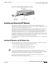
... Installation Guide 2-23 Determine which type of SFP modules that the Catalyst 2950 LRE switch supports. Each port must not exceed the stipulated cable length. This encoding provides a way for Cisco to install and remove small-form-factor pluggable (SFP) modules. Do not remove and ...cable stipulations for their installation and extraction. You can shorten its useful life. Use only Cisco SFP modules on the front of latches for SFP module connections. These field-replaceable modules provide the uplink interfaces. Each SFP module has an internal serial EEPROM that the SFP...
... Installation Guide 2-23 Determine which type of SFP modules that the Catalyst 2950 LRE switch supports. Each port must not exceed the stipulated cable length. This encoding provides a way for Cisco to install and remove small-form-factor pluggable (SFP) modules. Do not remove and ...cable stipulations for their installation and extraction. You can shorten its useful life. Use only Cisco SFP modules on the front of latches for SFP module connections. These field-replaceable modules provide the uplink interfaces. Each SFP module has an internal serial EEPROM that the SFP...

Hardware Installation Guide
Page 70
... SFP module into place in front of the SFP module. Note On some SFP modules, the send and receive (TX and RX) markings might be replaced by arrows that identify the top side of the slot opening. Insert the SFP module into the slot until you feel the connector on the... and to a bare metal surface on the chassis. Step 2 Find the send (TX) and receive (RX) markings that show the direction of the slot. 2-24 Catalyst 2950 Switch Hardware Installation Guide OL-6156-01 Step 3 Step 4 Align the SFP module in the rear of the connection, either send or receive (TX or RX).
... SFP module into place in front of the SFP module. Note On some SFP modules, the send and receive (TX and RX) markings might be replaced by arrows that identify the top side of the slot opening. Insert the SFP module into the slot until you feel the connector on the... and to a bare metal surface on the chassis. Step 2 Find the send (TX) and receive (RX) markings that show the direction of the slot. 2-24 Catalyst 2950 Switch Hardware Installation Guide OL-6156-01 Step 3 Step 4 Align the SFP module in the rear of the connection, either send or receive (TX or RX).

Hardware Installation Guide
Page 89
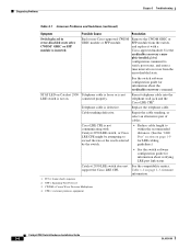
...If the fan has failed, call Cisco Systems. • Use the show env fan privileged EXEC command. Switch not recognizing an SFP module. Reset the terminal-emulation software to display the switch boot loader. Unreadable characters on page B-6. • Replace it with a tested good cable. ...-through cables, see the switch software configuration guide. • Check if the fan has failed by using the show post privileged EXEC command to your GBIC module documentation for port status LED to turn green. OL-6156-01 Catalyst 2950 Switch Hardware Installation Guide 3-3
...If the fan has failed, call Cisco Systems. • Use the show env fan privileged EXEC command. Switch not recognizing an SFP module. Reset the terminal-emulation software to display the switch boot loader. Unreadable characters on page B-6. • Replace it with a tested good cable. ...-through cables, see the switch software configuration guide. • Check if the fan has failed by using the show post privileged EXEC command to your GBIC module documentation for port status LED to turn green. OL-6156-01 Catalyst 2950 Switch Hardware Installation Guide 3-3
Hardware Installation Guide
Page 90
... global configuration command to verify port status, and enter a time interval to recover from the switch, and replace it with Catalyst 2950 LRE switch, or Cisco LRE CPE might be attempting to exceed the rate or the reach selected by the switch. • Reduce cable length to within the recommended distances. (See the "LRE Port" section...
... global configuration command to verify port status, and enter a time interval to recover from the switch, and replace it with Catalyst 2950 LRE switch, or Cisco LRE CPE might be attempting to exceed the rate or the reach selected by the switch. • Reduce cable length to within the recommended distances. (See the "LRE Port" section...

Hardware Installation Guide
Page 111
... areas. Preparing for this unit, contact your reseller or Cisco sales representative. Statement 1017 Warning Ethernet cables must comply with local and national electrical codes. C A P P E N D I X Connecting to DC Power To connect the Catalyst 2950G-24-EI-DC or Catalyst 2950ST-24 LRE 997 switch to remove or replace any components. Statement 171 Caution Installation of the equipment...
... areas. Preparing for this unit, contact your reseller or Cisco sales representative. Statement 1017 Warning Ethernet cables must comply with local and national electrical codes. C A P P E N D I X Connecting to DC Power To connect the Catalyst 2950G-24-EI-DC or Catalyst 2950ST-24 LRE 997 switch to remove or replace any components. Statement 171 Caution Installation of the equipment...

Hardware Installation Guide
Page 114
...replace this range, the switch might not operate properly or might be installed with all power is removed from -36 to the OFF position, and tape the switch handle of the circuit breaker in the OFF position. Statement 196 Caution You must be damaged. Caution The switch must connect the Catalyst 2950G-24-EI-DC or Catalyst... 2950ST-24 LRE 997 switch only to 15 lbf-in this equipment. CONSOLE Appendix C Connecting to DC Power 65295...
...replace this range, the switch might not operate properly or might be installed with all power is removed from -36 to the OFF position, and tape the switch handle of the circuit breaker in the OFF position. Statement 196 Caution You must be damaged. Caution The switch must connect the Catalyst 2950G-24-EI-DC or Catalyst... 2950ST-24 LRE 997 switch only to 15 lbf-in this equipment. CONSOLE Appendix C Connecting to DC Power 65295...