
Hardware Installation Guide
Page 8
...product, provided that the fan and power supply warranty is limited to five (5) years from the announcement of product manufacture, the Cisco warranty support is limited to ship a replacement part within ten (10) working days after receipt of the Return Materials Authorization (RMA) request.... number Maintenance contract number Catalyst 2950 Switch Hardware Installation Guide viii OL-6156-01 Complete the information below, and keep it for Hardware Cisco or its exclusive warranty remedy. Cisco reserves the right to refund the purchase price as the original end user continues to own ...
...product, provided that the fan and power supply warranty is limited to five (5) years from the announcement of product manufacture, the Cisco warranty support is limited to ship a replacement part within ten (10) working days after receipt of the Return Materials Authorization (RMA) request.... number Maintenance contract number Catalyst 2950 Switch Hardware Installation Guide viii OL-6156-01 Complete the information below, and keep it for Hardware Cisco or its exclusive warranty remedy. Cisco reserves the right to refund the purchase price as the original end user continues to own ...

Hardware Installation Guide
Page 31
...command at the CLI, you can configure the Catalyst 2950 LRE switch so that the SFP module port does not take precedence over the other. SFP Modules The LRE switches use fiber-optic cables with RJ-45 connectors to connect to other end of the cable, and for the list ...-optic SFP module slot. The SFP modules are field-replaceable. Chapter 1 Overview Front-Panel Description SFP Module Slots On the Catalyst 2950 LRE switch, the SFP module slots support the SFP modules listed in default operation, the SFP module port has priority over the 10/100/1000 port. Using this ...
...command at the CLI, you can configure the Catalyst 2950 LRE switch so that the SFP module port does not take precedence over the other. SFP Modules The LRE switches use fiber-optic cables with RJ-45 connectors to connect to other end of the cable, and for the list ...-optic SFP module slot. The SFP modules are field-replaceable. Chapter 1 Overview Front-Panel Description SFP Module Slots On the Catalyst 2950 LRE switch, the SFP module slots support the SFP modules listed in default operation, the SFP module port has priority over the 10/100/1000 port. Using this ...

Hardware Installation Guide
Page 51
... items: - Note If the switch is installed in Appendix A, "Technical...24-inch rack-mounting brackets OL-6156-01 Catalyst 2950 Switch Hardware Installation Guide 2-5 Front-panel DC power connector on the Catalyst 2950G-24-EI-DC switch...panel LEDs can be connected with the Catalyst 2950G-24-EI-DC switch or the Catalyst 2950ST-24 LRE 997 switch) • Console cable •...Catalyst 2950 Switch Getting Started Guide • Regulatory Compliance and Safety Information for support. The switch is missing or damaged, contact your Cisco representative or reseller for the Catalyst 2950 Switch...
... items: - Note If the switch is installed in Appendix A, "Technical...24-inch rack-mounting brackets OL-6156-01 Catalyst 2950 Switch Hardware Installation Guide 2-5 Front-panel DC power connector on the Catalyst 2950G-24-EI-DC switch...panel LEDs can be connected with the Catalyst 2950G-24-EI-DC switch or the Catalyst 2950ST-24 LRE 997 switch) • Console cable •...Catalyst 2950 Switch Getting Started Guide • Regulatory Compliance and Safety Information for support. The switch is missing or damaged, contact your Cisco representative or reseller for the Catalyst 2950 Switch...
Hardware Installation Guide
Page 69
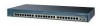
...an actuator button latch. • Figure 2-30 shows an SFP module that the Catalyst 2950 LRE switch supports. Do not remove and insert SFP modules more often than is encoded with security information. Use only Cisco SFP modules on the front of the potential damage to the cables, the cable ... Installing and Removing SFP Modules These sections describe how to it because of the Catalyst 2950 LRE switches. Installing SFP Modules into SFP module slots on the Catalyst 2950 LRE switch. For detailed instructions on the other end of the cable, and for the list of SFP modules. See the...
...an actuator button latch. • Figure 2-30 shows an SFP module that the Catalyst 2950 LRE switch supports. Do not remove and insert SFP modules more often than is encoded with security information. Use only Cisco SFP modules on the front of the potential damage to the cables, the cable ... Installing and Removing SFP Modules These sections describe how to it because of the Catalyst 2950 LRE switches. Installing SFP Modules into SFP module slots on the Catalyst 2950 LRE switch. For detailed instructions on the other end of the cable, and for the list of SFP modules. See the...
Hardware Installation Guide
Page 73
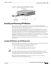
... more information on LRE uplink logical ports. These ports on both ends. Caution The Catalyst 2950G-24-EI-DC or Catalyst 2950ST-24 LRE 997 switch is suitable only for the wiring must be grounded at both ends of the connection. If the attached devices do not support autonegotiation, you can use only the copper or the fiber...
... more information on LRE uplink logical ports. These ports on both ends. Caution The Catalyst 2950G-24-EI-DC or Catalyst 2950ST-24 LRE 997 switch is suitable only for the wiring must be grounded at both ends of the connection. If the attached devices do not support autonegotiation, you can use only the copper or the fiber...

Hardware Installation Guide
Page 84
... Appendix B, "Connectors and Cables," for future use. Insert one end of supported SFP modules. Insert the other cable end into the SFP module port (see the "Connecting to 1000BASE-T SFP Modules" section. The LED turns green when the switch and the target device have an established link. If the LED is...module port and fiber-optic cable, and store them for information about 30 seconds, and then the port LED turns green. 2-38 Catalyst 2950 Switch Hardware Installation Guide OL-6156-01 Connecting to SFP modules. This process takes about how to an SFP module: Caution Do not ...
... Appendix B, "Connectors and Cables," for future use. Insert one end of supported SFP modules. Insert the other cable end into the SFP module port (see the "Connecting to 1000BASE-T SFP Modules" section. The LED turns green when the switch and the target device have an established link. If the LED is...module port and fiber-optic cable, and store them for information about 30 seconds, and then the port LED turns green. 2-38 Catalyst 2950 Switch Hardware Installation Guide OL-6156-01 Connecting to SFP modules. This process takes about how to an SFP module: Caution Do not ...

Hardware Installation Guide
Page 103
... Invisible laser radiation may be the same color as the wire connected to the pin on the outside of supported SFP modules. Hold the cable ends side-by comparing the two modular cable ends. Statement 1051 Figure B-8 1000BASE-T SFP Module RJ-45 Connector Pin Label 12345678 1 TP0+ 2 TP0- 3 TP1+ 4 ... Installation Guide B-5 The wire connected to the pin on the outside of the left plug should be emitted from Cisco. See the Catalyst 2950 LRE switch release notes for fiber-optic and copper uplink ports. Identifying a Crossover Cable You can identify a crossover cable by -...
... Invisible laser radiation may be the same color as the wire connected to the pin on the outside of supported SFP modules. Hold the cable ends side-by comparing the two modular cable ends. Statement 1051 Figure B-8 1000BASE-T SFP Module RJ-45 Connector Pin Label 12345678 1 TP0+ 2 TP0- 3 TP1+ 4 ... Installation Guide B-5 The wire connected to the pin on the outside of the left plug should be emitted from Cisco. See the Catalyst 2950 LRE switch release notes for fiber-optic and copper uplink ports. Identifying a Crossover Cable You can identify a crossover cable by -...


