Hardware Installation Guide
Page 2
.... • Move the equipment to this manual generates and may radiate radio-frequency energy. In that is on circuits controlled by using one or more of this document or Website are on a different circuit from the television or radio. • Plug the equipment... operated in a commercial environment. All rights reserved. If it was probably caused by the Cisco equipment or one side or the other company. (0406R) Catalyst 2950 Switch Hardware Installation Guide Copyright © 2004 Cisco Systems, Inc. This equipment has been tested and found to comply with FCC requirements for ...
.... • Move the equipment to this manual generates and may radiate radio-frequency energy. In that is on circuits controlled by using one or more of this document or Website are on a different circuit from the television or radio. • Plug the equipment... operated in a commercial environment. All rights reserved. If it was probably caused by the Cisco equipment or one side or the other company. (0406R) Catalyst 2950 Switch Hardware Installation Guide Copyright © 2004 Cisco Systems, Inc. This equipment has been tested and found to comply with FCC requirements for ...

Hardware Installation Guide
Page 7
...warranty information about your hardware warranty and various services that the part number 78-5235-02F0 is highlighted. Catalyst 2950 Switch Hardware Installation Guide vii Enter this URL: http://www.cisco.com/univercd/cc/td/doc/es_inpck/cetrans.htm The Warranties and License Agreements page appears. 2. The... the PDF icon to download and print the document in which you can use during the warranty period. Click Go. You can download the reader from the Information Packet appears. Cisco Limited Lifetime Hardware Warranty Terms OL-6156-01 There are special terms applicable...
...warranty information about your hardware warranty and various services that the part number 78-5235-02F0 is highlighted. Catalyst 2950 Switch Hardware Installation Guide vii Enter this URL: http://www.cisco.com/univercd/cc/td/doc/es_inpck/cetrans.htm The Warranties and License Agreements page appears. 2. The... the PDF icon to download and print the document in which you can use during the warranty period. Click Go. You can download the reader from the Information Packet appears. Cisco Limited Lifetime Hardware Warranty Terms OL-6156-01 There are special terms applicable...

Hardware Installation Guide
Page 8
...after receipt of the Return Materials Authorization (RMA) request. Cisco Limited Lifetime Hardware Warranty Terms Duration of Hardware Warranty A Cisco product hardware warranty is supported for as long as its service center will use the product, provided that the fan and power supply ...warranty is limited to five (5) years from Company telephone number Product model number Product serial number Maintenance contract number Catalyst 2950 Switch...
...after receipt of the Return Materials Authorization (RMA) request. Cisco Limited Lifetime Hardware Warranty Terms Duration of Hardware Warranty A Cisco product hardware warranty is supported for as long as its service center will use the product, provided that the fan and power supply ...warranty is limited to five (5) years from Company telephone number Product model number Product serial number Maintenance contract number Catalyst 2950 Switch...

Hardware Installation Guide
Page 9
... guide describes the hardware features of the switch, explains how to as the switch. OL-6156-01 Catalyst 2950 Switch Hardware Installation Guide ix Conventions Command descriptions use by the switch. Preface Audience This guide is for the networking or computer technician responsible for installing a Catalyst 2950 switch, hereafter referred to install a switch, and provides troubleshooting information and specifications.
... guide describes the hardware features of the switch, explains how to as the switch. OL-6156-01 Catalyst 2950 Switch Hardware Installation Guide ix Conventions Command descriptions use by the switch. Preface Audience This guide is for the networking or computer technician responsible for installing a Catalyst 2950 switch, hereafter referred to install a switch, and provides troubleshooting information and specifications.

Hardware Installation Guide
Page 10
...in the translated safety warnings that could cause bodily injury. Tilanne voi aiheuttaa ruumiillisia vammoja. CONSERVEZ CES INFORMATIONS Catalyst 2950 Switch Hardware Installation Guide x OL-6156-01 Conventions Preface Caution Means reader be familiar with electrical circuitry and be ... of the hazards involved with standard practices for preventing accidents. Warning IMPORTANT SAFETY INSTRUCTIONS This warning symbol means danger. Use the statement number provided at the end of data. BEWAAR DEZE INSTRUCTIES Varoitus TÄRKEITÄ TURVALLISUUSOHJEITA Täm&#...
...in the translated safety warnings that could cause bodily injury. Tilanne voi aiheuttaa ruumiillisia vammoja. CONSERVEZ CES INFORMATIONS Catalyst 2950 Switch Hardware Installation Guide x OL-6156-01 Conventions Preface Caution Means reader be familiar with electrical circuitry and be ... of the hazards involved with standard practices for preventing accidents. Warning IMPORTANT SAFETY INSTRUCTIONS This warning symbol means danger. Use the statement number provided at the end of data. BEWAAR DEZE INSTRUCTIES Varoitus TÄRKEITÄ TURVALLISUUSOHJEITA Täm&#...
Hardware Installation Guide
Page 18
.... xviii Catalyst 2950 Switch Hardware Installation Guide OL-6156-01 Obtaining Technical Assistance Preface Documentation Feedback You can submit comments by using these recommendations, your case will be assigned to a Cisco TAC engineer. The Cisco TAC website is down or severely degraded) or if you describe your production network is available 24 hours a day, 365 days...
.... xviii Catalyst 2950 Switch Hardware Installation Guide OL-6156-01 Obtaining Technical Assistance Preface Documentation Feedback You can submit comments by using these recommendations, your case will be assigned to a Cisco TAC engineer. The Cisco TAC website is down or severely degraded) or if you describe your production network is available 24 hours a day, 365 days...

Hardware Installation Guide
Page 19
... Publications and Information To open a case by telephone, use one of the following numbers: Asia-Pacific: +61 2 8446 7411 (Australia: 1 800 805 227) EMEA: +32 2 704 55 55 USA: 1 800 553-2447 For a complete listing of Cisco TAC contacts, go /iqmagazine OL-6156-01 Catalyst 2950 Switch Hardware Installation Guide xix Priority 3 (P3)-Operational...
... Publications and Information To open a case by telephone, use one of the following numbers: Asia-Pacific: +61 2 8446 7411 (Australia: 1 800 805 227) EMEA: +32 2 704 55 55 USA: 1 800 553-2447 For a complete listing of Cisco TAC contacts, go /iqmagazine OL-6156-01 Catalyst 2950 Switch Hardware Installation Guide xix Priority 3 (P3)-Operational...
Hardware Installation Guide
Page 21
... connection procedures for both AC- Catalyst 2950-24 switch-24 10/100 Ethernet ports - Figure 1-1 through Figure 1-12 show how you can use switches with the CLI-Based Setup Program." Also covered in your network. Features The Catalyst 2950 switches are stackable. Some switch models can use to create switch stacks by using Gigastack GBICs. All models of the switch are cluster-capable, but...
... connection procedures for both AC- Catalyst 2950-24 switch-24 10/100 Ethernet ports - Figure 1-1 through Figure 1-12 show how you can use switches with the CLI-Based Setup Program." Also covered in your network. Features The Catalyst 2950 switches are stackable. Some switch models can use to create switch stacks by using Gigastack GBICs. All models of the switch are cluster-capable, but...

Hardware Installation Guide
Page 23
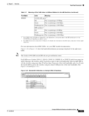
... "Power Connectors" section on page 1-24. In Table 1-1, Yes means that uses AC input and supplies DC output to the switch - Table 1-1 LRE Switch and CPE Compatibility Matrix LRE Devices Catalyst 2950ST-8 LRE Cisco 575 LRE Yes CPE Cisco 576 LRE 997 No CPE Cisco 585 LRE Yes CPE Catalyst 2950ST-24 LRE Catalyst 2950ST-24 LRE 997 Yes No No Yes...
... "Power Connectors" section on page 1-24. In Table 1-1, Yes means that uses AC input and supplies DC output to the switch - Table 1-1 LRE Switch and CPE Compatibility Matrix LRE Devices Catalyst 2950ST-8 LRE Cisco 575 LRE Yes CPE Cisco 576 LRE 997 No CPE Cisco 585 LRE Yes CPE Catalyst 2950ST-24 LRE Catalyst 2950ST-24 LRE 997 Yes No No Yes...
Hardware Installation Guide
Page 27
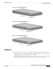
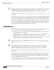
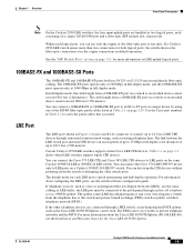
OL-6156-01 Catalyst 2950 Switch Hardware Installation Guide 1-7 The ports can use RJ-45 connectors and twisted-pair cabling. Chapter 1 Overview Figure 1-12 Catalyst 2950T-24 Switch Front-Panel Description 47337 SYST RPS STAT UTIL DUPLX SPEED MODE 1x 2x 3x 4x 5x 6x 7x 8x 9x 10x 11x 10Base-T /... 100Base-TX 12x 13x 14x 15x 16x 17x 18x 19x 20x 21x 22x 23x Catalyst 2950 SERIES 24x 10/100/100Base-T 1 2 10/100 ports 10/100/1000 ports Figure 1-13 Catalyst 2950SX-48-SI Switch 97630 SYST RPS STAT UTIL DUPLX SPEED MODE 1 1X 2X 23 45 67 8 9 10 11...
OL-6156-01 Catalyst 2950 Switch Hardware Installation Guide 1-7 The ports can use RJ-45 connectors and twisted-pair cabling. Chapter 1 Overview Figure 1-12 Catalyst 2950T-24 Switch Front-Panel Description 47337 SYST RPS STAT UTIL DUPLX SPEED MODE 1x 2x 3x 4x 5x 6x 7x 8x 9x 10x 11x 10Base-T /... 100Base-TX 12x 13x 14x 15x 16x 17x 18x 19x 20x 21x 22x 23x Catalyst 2950 SERIES 24x 10/100/100Base-T 1 2 10/100 ports 10/100/1000 ports Figure 1-13 Catalyst 2950SX-48-SI Switch 97630 SYST RPS STAT UTIL DUPLX SPEED MODE 1 1X 2X 23 45 67 8 9 10 11...
Hardware Installation Guide
Page 28
... 1000BASE-T devices, such as high-speed workstations, servers, hubs, routers, and other switches, through standard RJ-45 connectors and four twisted-pair, Category 5 cabling. For information on the Catalyst 2950T-24 switch can connect to an attached device cannot exceed 328 feet (100 meters). The ports ... only in any combination of the attached device and advertises its own capabilities. When connecting the switch to the "Identifying a Crossover Cable" section on Catalyst 2950T-24, Catalyst 2950T-48-SI, and Catalyst 2950 LRE switches use a twisted-pair straight-through cable.
... 1000BASE-T devices, such as high-speed workstations, servers, hubs, routers, and other switches, through standard RJ-45 connectors and four twisted-pair, Category 5 cabling. For information on the Catalyst 2950T-24 switch can connect to an attached device cannot exceed 328 feet (100 meters). The ports ... only in any combination of the attached device and advertises its own capabilities. When connecting the switch to the "Identifying a Crossover Cable" section on Catalyst 2950T-24, Catalyst 2950T-48-SI, and Catalyst 2950 LRE switches use a twisted-pair straight-through cable.
Hardware Installation Guide
Page 29
...autosensing and half-duplex operation. Table 1-1 on a Catalyst 2950ST-24 LRE 997 switch. You can be connected to an attached device cannot exceed 1804 feet (550 meters). The default mode for both use the same cabling as the Cisco LRE 48 POTS Splitter, can hot swap the CPE...disrupting the other telephone services are bundled as two logical ports, each logical port, you need. Use the Cisco part numbers in Table 2-1 on page 2-29. Certain Catalyst 2950 LRE switches support certain Cisco LRE CPE devices. The splitter routes LRE data (high-frequency) and voice (low-frequency) ...
...autosensing and half-duplex operation. Table 1-1 on a Catalyst 2950ST-24 LRE 997 switch. You can be connected to an attached device cannot exceed 1804 feet (550 meters). The default mode for both use the same cabling as the Cisco LRE 48 POTS Splitter, can hot swap the CPE...disrupting the other telephone services are bundled as two logical ports, each logical port, you need. Use the Cisco part numbers in Table 2-1 on page 2-29. Certain Catalyst 2950 LRE switches support certain Cisco LRE CPE devices. The splitter routes LRE data (high-frequency) and voice (low-frequency) ...

Hardware Installation Guide
Page 30
... is inserted in an error-disabled state. For more information about homologated POTS splitters, contact your GBIC module documentation. 1-10 Catalyst 2950 Switch Hardware Installation Guide OL-6156-01 Using the required Cisco proprietary signaling and cabling, the GigaStack GBIC-to other Gigabit Ethernet devices. The GigaStack GBIC supports one full-duplex link (in...
... is inserted in an error-disabled state. For more information about homologated POTS splitters, contact your GBIC module documentation. 1-10 Catalyst 2950 Switch Hardware Installation Guide OL-6156-01 Using the required Cisco proprietary signaling and cabling, the GigaStack GBIC-to other Gigabit Ethernet devices. The GigaStack GBIC supports one full-duplex link (in...

Hardware Installation Guide
Page 31
... connect to 328 feet (100 meters). • Table 1-2 lists the cable specifications for the list of the Catalyst 2950 LRE switches. SFP Modules The LRE switches use fiber-optic cables with RJ-45 connectors to connect to 1550 nanometers (nm). Chapter 1 Overview Front-Panel Description...media-type {sfp | rj45 | auto-select} command, see the switch command reference. You use Ethernet SFP modules to establish uplink connections to both, in the Catalyst 2950 LRE switch release notes. See the Catalyst 2950 LRE switch release notes for 1000BASE-SX, 1000BASE-LX, and 1000BASE-ZX fiber...
... connect to 328 feet (100 meters). • Table 1-2 lists the cable specifications for the list of the Catalyst 2950 LRE switches. SFP Modules The LRE switches use fiber-optic cables with RJ-45 connectors to connect to 1550 nanometers (nm). Chapter 1 Overview Front-Panel Description...media-type {sfp | rj45 | auto-select} command, see the switch command reference. You use Ethernet SFP modules to establish uplink connections to both, in the Catalyst 2950 LRE switch release notes. See the Catalyst 2950 LRE switch release notes for 1000BASE-SX, 1000BASE-LX, and 1000BASE-ZX fiber...

Hardware Installation Guide
Page 32
...serial number, the vendor name or ID, security code, or CRC is invalid, the switch places the interface in an elevated bit error rate (BER). Using an ordinary patch cord with a Cisco-approved module. When the fiber-optic cable span is inserted in the link to 62 ...end of the link. Note When using dispersion-shifted SMF or low-attenuation SMF; For more information about these SFP modules, see your SFP module documentation. 1-12 Catalyst 2950 Switch Hardware Installation Guide OL-6156-01 the distance depends on the Catalyst 2950 LRE switch. Front-Panel Description Chapter 1 ...
...serial number, the vendor name or ID, security code, or CRC is invalid, the switch places the interface in an elevated bit error rate (BER). Using an ordinary patch cord with a Cisco-approved module. When the fiber-optic cable span is inserted in the link to 62 ...end of the link. Note When using dispersion-shifted SMF or low-attenuation SMF; For more information about these SFP modules, see your SFP module documentation. 1-12 Catalyst 2950 Switch Hardware Installation Guide OL-6156-01 the distance depends on the Catalyst 2950 LRE switch. Front-Panel Description Chapter 1 ...

Hardware Installation Guide
Page 33
... GUI management applications-the Network Assistant application for multiple switches and the device manager for a single switch. The switch software configuration guide describes how to use to select the port mode also varies by model. Figure 1-15 LEDs on Catalyst 2950-12, 2950-24, 2950C-24, 2950SX-24, and 2950T-24 Switches RPS LED Port status LEDs System LED Port mode...
... GUI management applications-the Network Assistant application for multiple switches and the device manager for a single switch. The switch software configuration guide describes how to use to select the port mode also varies by model. Figure 1-15 LEDs on Catalyst 2950-12, 2950-24, 2950C-24, 2950SX-24, and 2950T-24 Switches RPS LED Port status LEDs System LED Port mode...

Hardware Installation Guide
Page 37
.... Port was powered on a logarithmic scale. Green and amber See Figure 1-20 to 30 seconds while STP checks the switch for possible loops. The bandwidth in use by management, an address violation, or Spanning Tree Protocol (STP). Port is the default mode. Alternating green-amber Link ... remain amber for up to Figure 1-24 for the non-LRE switches. DUPLX Off Port is operating in half duplex. (half or full duplex) Green Port is operating in Different Modes for a link-fault indication. OL-6156-01 Catalyst 2950 Switch Hardware Installation Guide 1-17 SPEED Port speed...
.... Port was powered on a logarithmic scale. Green and amber See Figure 1-20 to 30 seconds while STP checks the switch for possible loops. The bandwidth in use by management, an address violation, or Spanning Tree Protocol (STP). Port is the default mode. Alternating green-amber Link ... remain amber for up to Figure 1-24 for the non-LRE switches. DUPLX Off Port is operating in half duplex. (half or full duplex) Green Port is operating in Different Modes for a link-fault indication. OL-6156-01 Catalyst 2950 Switch Hardware Installation Guide 1-17 SPEED Port speed...
Hardware Installation Guide
Page 39
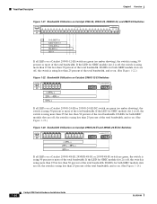
...Port is operating at 1000 Mbps. Green Port is operating at 1000 Mbps 1. If all LEDs on a Catalyst 2950-12, 2950-24, 2950C-24, 2950SX-24, or 2950T-24 switch are green (no amber showing), the switch is using 50 percent or more of the total bandwidth, and so on. If the far-right LED is off,... the switch is using less than 50 percent of the total bandwidth. Flashing green Port is operating at 10 ...
...Port is operating at 1000 Mbps. Green Port is operating at 1000 Mbps 1. If all LEDs on a Catalyst 2950-12, 2950-24, 2950C-24, 2950SX-24, or 2950T-24 switch are green (no amber showing), the switch is using 50 percent or more of the total bandwidth, and so on. If the far-right LED is off,... the switch is using less than 50 percent of the total bandwidth. Flashing green Port is operating at 10 ...
Hardware Installation Guide
Page 40
... percent of the total bandwidth. If the LED for GBIC module slot 2 is off , the switch is using more of the total bandwidth. Front-Panel Description Chapter 1 Overview Figure 1-21 Bandwidth Utilization on Catalyst 2950-24, 2950C-24, 2950SX-24, and 2950T-24 Switches SYST RPS STAT UTIL DUPLX SPEED MODE 1x 2x 3x 4x 5x 6x 7x 8x...
... percent of the total bandwidth. If the LED for GBIC module slot 2 is off , the switch is using more of the total bandwidth. Front-Panel Description Chapter 1 Overview Figure 1-21 Bandwidth Utilization on Catalyst 2950-24, 2950C-24, 2950SX-24, and 2950T-24 Switches SYST RPS STAT UTIL DUPLX SPEED MODE 1x 2x 3x 4x 5x 6x 7x 8x...

Hardware Installation Guide
Page 42
... Installation Guide OL-6156-01 Other than for the Catalyst 2950G-24-EI-DC and the Catalyst 2950ST-24 LRE 997 switches, use the supplied AC power cord to connect the AC power connector to a switch by using the AC internal power supply, the DC-input power source, or the Cisco RPS. Internal Power Supply Connector The internal AC...
... Installation Guide OL-6156-01 Other than for the Catalyst 2950G-24-EI-DC and the Catalyst 2950ST-24 LRE 997 switches, use the supplied AC power cord to connect the AC power connector to a switch by using the AC internal power supply, the DC-input power source, or the Cisco RPS. Internal Power Supply Connector The internal AC...


