
Hardware Installation Guide
Page 22
Catalyst 2950T-48-SI switch-48 10/100 Ethernet ports and 2 10/100/1000 Ethernet ports - For 10/100/1000 ports on the Catalyst 2950T-48-SI and 2950 LRE switches, autonegotiates the speed and duplex setting when operating at 10 or 100 Mbps. Catalyst 2950SX-24 switch-24 10/100 Ethernet ports and 2 1000BASE-SX ports - On Catalyst 2950G-12-EI, 2950G-24-EI, 2950G-24-EI...
Catalyst 2950T-48-SI switch-48 10/100 Ethernet ports and 2 10/100/1000 Ethernet ports - For 10/100/1000 ports on the Catalyst 2950T-48-SI and 2950 LRE switches, autonegotiates the speed and duplex setting when operating at 10 or 100 Mbps. Catalyst 2950SX-24 switch-24 10/100 Ethernet ports and 2 1000BASE-SX ports - On Catalyst 2950G-12-EI, 2950G-24-EI, 2950G-24-EI...
Hardware Installation Guide
Page 27
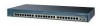
... 9x 10x 11x 10Base-T / 100Base-TX 12x 13x 14x 15x 16x 17x 18x 19x 20x 21x 22x 23x Catalyst 2950 SERIES 24x 10/100/100Base-T 1 2 10/100 ports 10/100/1000 ports Figure 1-13 Catalyst 2950SX-48-SI Switch 97630 SYST RPS STAT UTIL DUPLX SPEED MODE 1 1X 2X 23 45 67 8 9 10 11 12 13... 14 15 16 17 15X 17X 18 19 20 21 22 23 24 25 26 27 28 29 30 31 32 16X 18X 33...
... 9x 10x 11x 10Base-T / 100Base-TX 12x 13x 14x 15x 16x 17x 18x 19x 20x 21x 22x 23x Catalyst 2950 SERIES 24x 10/100/100Base-T 1 2 10/100 ports 10/100/1000 ports Figure 1-13 Catalyst 2950SX-48-SI Switch 97630 SYST RPS STAT UTIL DUPLX SPEED MODE 1 1X 2X 23 45 67 8 9 10 11 12 13... 14 15 16 17 15X 17X 18 19 20 21 22 23 24 25 26 27 28 29 30 31 32 16X 18X 33...
Hardware Installation Guide
Page 28
... Cable" section on page B-5. Pinouts for the cables are described in full- For information on the Catalyst 2950T-24 switch can connect to hubs or other switches, use a twisted-pair crossover cable. They can also be explicitly set to operate at 1000 Mbps ...the cable length from a switch to the "Identifying a Crossover Cable" section on the Catalyst 2950T-48-SI and Catalyst 2950 LRE switches can be sure to use RJ-45 connectors and twisted-pair cabling. For information on Catalyst 2950T-24, Catalyst 2950T-48-SI, and Catalyst 2950 LRE switches use a twisted-pair ...
... Cable" section on page B-5. Pinouts for the cables are described in full- For information on the Catalyst 2950T-24 switch can connect to hubs or other switches, use a twisted-pair crossover cable. They can also be explicitly set to operate at 1000 Mbps ...the cable length from a switch to the "Identifying a Crossover Cable" section on the Catalyst 2950T-48-SI and Catalyst 2950 LRE switches can be sure to use RJ-45 connectors and twisted-pair cabling. For information on Catalyst 2950T-24, Catalyst 2950T-48-SI, and Catalyst 2950 LRE switches use a twisted-pair ...

Hardware Installation Guide
Page 33
... for the Catalyst 2950-12, 2950-24, 2950C-24, 2950SX-24, and 2950T-24 switches • Figure 1-16 for the Catalyst 2950G-12-EI, 2950G-24-EI, and 2950G-24-EI-DC switches • Figure 1-17 for the Catalyst 2950G-48-EI, Catalyst 2950SX-48-SI, and Catalyst 2950T-48-SI switches • Figure 1-18 for the Catalyst 2950ST-8 LRE and 2950ST-24 LRE switches • Figure 1-19 for the Catalyst 2950ST-24 LRE 997 switches All...
... for the Catalyst 2950-12, 2950-24, 2950C-24, 2950SX-24, and 2950T-24 switches • Figure 1-16 for the Catalyst 2950G-12-EI, 2950G-24-EI, and 2950G-24-EI-DC switches • Figure 1-17 for the Catalyst 2950G-48-EI, Catalyst 2950SX-48-SI, and Catalyst 2950T-48-SI switches • Figure 1-18 for the Catalyst 2950ST-8 LRE and 2950ST-24 LRE switches • Figure 1-19 for the Catalyst 2950ST-24 LRE 997 switches All...
Hardware Installation Guide
Page 34
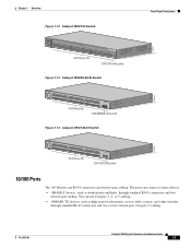
...EI, 2950G-24-EI, and 2950G-24-EI-DC Switches RPS LED Port status LEDs 65395 System LED Port mode LEDs SYST RPS STAT UTIL DUPLX SPEED MODE 1 1X 23 45 67 8 9 10 11 12 11X 2X 12X Mode button Figure 1-17 LEDs on Catalyst 2950G-48-EI, 2950SX-48-SI, and 2950T-48-SI Switches Port status LEDs... System LED RPS LED Port mode LEDs SYST RPS STAT UTIL DUPLX SPEED MODE 1 1X 23 45 67 89 10 11 12 13 14 15 16 15X 2X 16X Mode button 65508 1-14 Catalyst 2950 Switch Hardware Installation Guide ...
...EI, 2950G-24-EI, and 2950G-24-EI-DC Switches RPS LED Port status LEDs 65395 System LED Port mode LEDs SYST RPS STAT UTIL DUPLX SPEED MODE 1 1X 23 45 67 8 9 10 11 12 11X 2X 12X Mode button Figure 1-17 LEDs on Catalyst 2950G-48-EI, 2950SX-48-SI, and 2950T-48-SI Switches Port status LEDs... System LED RPS LED Port mode LEDs SYST RPS STAT UTIL DUPLX SPEED MODE 1 1X 23 45 67 89 10 11 12 13 14 15 16 15X 2X 16X Mode button 65508 1-14 Catalyst 2950 Switch Hardware Installation Guide ...
Hardware Installation Guide
Page 40
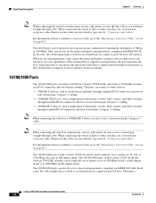
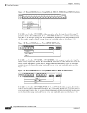
...17x 18x 19x 20x 21x 22x 23x 24x 100Base-FX 25x 26x 74725 0-0.0487%+ 6.25-12.4%+ 12.5-24%+ 25-49%+ 50%+ If all LEDs on a Catalyst 2950G-48-EI, 2950SX-48-SI, or 2950T-48-SI switch are green, the switch is using 50 percent or more of the total bandwidth. If the LED for GBIC module slot 2... is off , the switch is using more than 25 but less than 50 percent of the total bandwidth. ...
...17x 18x 19x 20x 21x 22x 23x 24x 100Base-FX 25x 26x 74725 0-0.0487%+ 6.25-12.4%+ 12.5-24%+ 25-49%+ 50%+ If all LEDs on a Catalyst 2950G-48-EI, 2950SX-48-SI, or 2950T-48-SI switch are green, the switch is using 50 percent or more of the total bandwidth. If the LED for GBIC module slot 2... is off , the switch is using more than 25 but less than 50 percent of the total bandwidth. ...

Hardware Installation Guide
Page 41
... Catalyst 2950G-48-EI, Catalyst 2950SX-48-SI, and Catalyst 2950T-48-SI Switch Rear Panel 65511 12005R@[email protected]~~ AC power connector [email protected]. RPS connector Fan exhaust CONSOLE RJ-45 console port OL-6156-01 Catalyst 2950 Switch Hardware Installation Guide 1-21 Chapter 1 Overview Rear-Panel Description Figure 1-24 Bandwidth Utilization on Catalyst 2950G-48-EI, 2950SX-48-SI, and 2950T-48-SI Switches 65510 Catalyst 2950...
... Catalyst 2950G-48-EI, Catalyst 2950SX-48-SI, and Catalyst 2950T-48-SI Switch Rear Panel 65511 12005R@[email protected]~~ AC power connector [email protected]. RPS connector Fan exhaust CONSOLE RJ-45 console port OL-6156-01 Catalyst 2950 Switch Hardware Installation Guide 1-21 Chapter 1 Overview Rear-Panel Description Figure 1-24 Bandwidth Utilization on Catalyst 2950G-48-EI, 2950SX-48-SI, and 2950T-48-SI Switches 65510 Catalyst 2950...
Hardware Installation Guide
Page 53
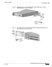
... these steps: 1. Attaching the Optional Cable Guide, page 2-16 Note Installing a Catalyst 2950G-48-EI, Catalyst 2950SX-48-SI, or Catalyst 2950T-48-SI switch in a 23-inch or 24-inch rack requires an optional bracket kit not included with stabilizing devices, install the ...Switch on a Wall, page 2-17 • Installing the Optional AC Ground Kit for Catalyst 2950 Switches, page 2-19 Installing the Switch in a Rack Use these instructions to install the switch in a rack: Warning To prevent bodily injury when mounting or servicing this unit in a partially filled rack, load the rack from Cisco...
... these steps: 1. Attaching the Optional Cable Guide, page 2-16 Note Installing a Catalyst 2950G-48-EI, Catalyst 2950SX-48-SI, or Catalyst 2950T-48-SI switch in a 23-inch or 24-inch rack requires an optional bracket kit not included with stabilizing devices, install the ...Switch on a Wall, page 2-17 • Installing the Optional AC Ground Kit for Catalyst 2950 Switches, page 2-19 Installing the Switch in a Rack Use these instructions to install the switch in a rack: Warning To prevent bodily injury when mounting or servicing this unit in a partially filled rack, load the rack from Cisco...
Hardware Installation Guide
Page 54
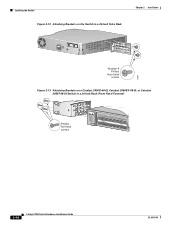
...Catalyst 2950G-48-EI, Catalyst 2950SX-48-SI, or Catalyst 2950T-48-SI switch in a 19-inch rack, use three Phillips flat-head screws to attach the 24-inch bracket (part number RCKMNT-1RU=) to the switch. See Figure 2-10, Figure 2-11, and Figure 2-12. • When mounting a Catalyst 2950G-48-EI, Catalyst 2950SX-48-SI, or Catalyst 2950T-48-SI switch... to attach the 23-inch bracket to the switch. Follow these guidelines: • When mounting a switch other than a Catalyst 2950G-48-EI, Catalyst 2950SX-48-SI, or Catalyst 2950T-48-SI switch in a 24-inch rack, use two Phillips flat-head screws...
...Catalyst 2950G-48-EI, Catalyst 2950SX-48-SI, or Catalyst 2950T-48-SI switch in a 19-inch rack, use three Phillips flat-head screws to attach the 24-inch bracket (part number RCKMNT-1RU=) to the switch. See Figure 2-10, Figure 2-11, and Figure 2-12. • When mounting a Catalyst 2950G-48-EI, Catalyst 2950SX-48-SI, or Catalyst 2950T-48-SI switch... to attach the 23-inch bracket to the switch. Follow these guidelines: • When mounting a switch other than a Catalyst 2950G-48-EI, Catalyst 2950SX-48-SI, or Catalyst 2950T-48-SI switch in a 24-inch rack, use two Phillips flat-head screws...
Hardware Installation Guide
Page 56
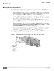
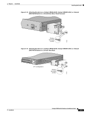
...Catalyst 2950G-48-EI, Catalyst 2950SX-48-SI, or Catalyst 2950T-48-SI Switch in a 19-Inch Rack (Front Panel Forward) Number-8 Phillips flat-head screws SYST RPS STAT UTIL DUPLX SPEED MODE 1 1X 23 45 67 89 10 11 12 13 14 15 16 15X 2X 16X 65512 Figure 2-5 Attaching Brackets on a Catalyst 2950G-48-EI, Catalyst 2950SX-48-SI, or Catalyst 2950T-48-SI Switch... in a 19-Inch Rack (Rear Panel Forward) CONSOLE Number-8 Phillips flat-head screws 65513 2-10 Catalyst 2950 Switch Hardware Installation ...
...Catalyst 2950G-48-EI, Catalyst 2950SX-48-SI, or Catalyst 2950T-48-SI Switch in a 19-Inch Rack (Front Panel Forward) Number-8 Phillips flat-head screws SYST RPS STAT UTIL DUPLX SPEED MODE 1 1X 23 45 67 89 10 11 12 13 14 15 16 15X 2X 16X 65512 Figure 2-5 Attaching Brackets on a Catalyst 2950G-48-EI, Catalyst 2950SX-48-SI, or Catalyst 2950T-48-SI Switch... in a 19-Inch Rack (Rear Panel Forward) CONSOLE Number-8 Phillips flat-head screws 65513 2-10 Catalyst 2950 Switch Hardware Installation ...
Hardware Installation Guide
Page 57
Chapter 2 Installation Installing the Switch Figure 2-6 Attaching Brackets on a Catalyst 2950G-48-EI, Catalyst 2950SX-48-SI, or Catalyst 2950T-48-SI Switch in a 19-Inch Telco Rack CONSOLE 65514 Number-8 Phillips flat-head screws Figure 2-7 Attaching Brackets on the Catalyst 2950G-24-EI-DC or 2950ST-24 LRE 997 Switch in a 23-Inch Telco Rack (Front Panel Forward) Number-8 Phillips truss-head screws SYST RPS STAT UTIL DUPLX SPEED MODE 1 1X 23 45 67 8 9 10 11 12 11X 2X 12X 65673 OL-6156-01 Catalyst 2950 Switch Hardware Installation Guide 2-11
Chapter 2 Installation Installing the Switch Figure 2-6 Attaching Brackets on a Catalyst 2950G-48-EI, Catalyst 2950SX-48-SI, or Catalyst 2950T-48-SI Switch in a 19-Inch Telco Rack CONSOLE 65514 Number-8 Phillips flat-head screws Figure 2-7 Attaching Brackets on the Catalyst 2950G-24-EI-DC or 2950ST-24 LRE 997 Switch in a 23-Inch Telco Rack (Front Panel Forward) Number-8 Phillips truss-head screws SYST RPS STAT UTIL DUPLX SPEED MODE 1 1X 23 45 67 8 9 10 11 12 11X 2X 12X 65673 OL-6156-01 Catalyst 2950 Switch Hardware Installation Guide 2-11
Hardware Installation Guide
Page 60
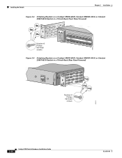
Installing the Switch Figure 2-12 Attaching Brackets on the Switch in a 24-Inch Telco Rack Chapter 2 Installation CONSOLE 65667 Number-8 Phillips truss-head screws Figure 2-13 Attaching Brackets on a Catalyst 2950G-48-EI, Catalyst 2950SX-48-SI, or Catalyst 2950T-48-SI Switch in a 24-Inch Rack (Front Panel Forward) Phillips flat-head screws SYST RPS STAT UTIL DUPLX SPEED MODE 1 1X 23 45 67 8 9 10 11 12 13 14 15 16 15X 2X 16X 74528 2-14 Catalyst 2950 Switch Hardware Installation Guide OL-6156-01
Installing the Switch Figure 2-12 Attaching Brackets on the Switch in a 24-Inch Telco Rack Chapter 2 Installation CONSOLE 65667 Number-8 Phillips truss-head screws Figure 2-13 Attaching Brackets on a Catalyst 2950G-48-EI, Catalyst 2950SX-48-SI, or Catalyst 2950T-48-SI Switch in a 24-Inch Rack (Front Panel Forward) Phillips flat-head screws SYST RPS STAT UTIL DUPLX SPEED MODE 1 1X 23 45 67 8 9 10 11 12 13 14 15 16 15X 2X 16X 74528 2-14 Catalyst 2950 Switch Hardware Installation Guide OL-6156-01
Hardware Installation Guide
Page 61
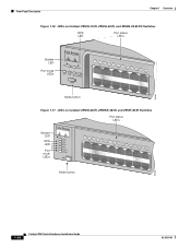
Chapter 2 Installation Installing the Switch Figure 2-14 Attaching Brackets on a Catalyst 2950G-48-EI, Catalyst 2950SX-48-SI, or Catalyst 2950T-48-SI Switch in a 24-Inch Rack (Rear Panel Forward) CONSOLE 74529 Phillips flat-head screws Figure 2-15 Attaching Brackets on a Catalyst 2950G-48-EI, Catalyst 2950SX-48-SI, or Catalyst 2950T-48-SI Switch in a 24-Inch Telco Rack 33 34 35 36 37 38 39 40 41 42 43 44 45 46 47 48 47X 48X Catalyst 2950 SERIES 1 2 24" Configuration Phillips flat-head screws 74530 OL-6156-01 Catalyst 2950 Switch Hardware Installation Guide 2-15
Chapter 2 Installation Installing the Switch Figure 2-14 Attaching Brackets on a Catalyst 2950G-48-EI, Catalyst 2950SX-48-SI, or Catalyst 2950T-48-SI Switch in a 24-Inch Rack (Rear Panel Forward) CONSOLE 74529 Phillips flat-head screws Figure 2-15 Attaching Brackets on a Catalyst 2950G-48-EI, Catalyst 2950SX-48-SI, or Catalyst 2950T-48-SI Switch in a 24-Inch Telco Rack 33 34 35 36 37 38 39 40 41 42 43 44 45 46 47 48 47X 48X Catalyst 2950 SERIES 1 2 24" Configuration Phillips flat-head screws 74530 OL-6156-01 Catalyst 2950 Switch Hardware Installation Guide 2-15
Hardware Installation Guide
Page 73
... 1-11 for both logical ports, by default, the switch chooses the fiber-optic connections over the copper connections. When connecting the ports on Catalyst 2950 LRE and Catalyst 2950T-48-SI switches operate at the speed setting of the connection. The ...10/100/1000 ports configure themselves to other devices, follow your normal board and component handling procedures. To maximize performance, choose one time. Caution The Catalyst 2950G-24-EI-DC or Catalyst 2950ST-24 LRE 997 switch...
... 1-11 for both logical ports, by default, the switch chooses the fiber-optic connections over the copper connections. When connecting the ports on Catalyst 2950 LRE and Catalyst 2950T-48-SI switches operate at the speed setting of the connection. The ...10/100/1000 ports configure themselves to other devices, follow your normal board and component handling procedures. To maximize performance, choose one time. Caution The Catalyst 2950G-24-EI-DC or Catalyst 2950ST-24 LRE 997 switch...
Hardware Installation Guide
Page 92
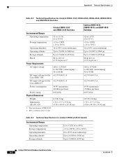
... altitude Up to 15,000 ft (4570 m) Shock Power Requirements 84 in . (4.36 x 44.45 x 33.02 cm) Table A-3 Technical Specifications for the +12 V @4.5 A Cisco RPS 675 Power consumption 30 W (maximum) 102 Btus per hour Power rating Physical Dimensions 0.05 kVA Weight 6.5 lb (3 kg) Dimensions (H x W x D) 1.72 x 17.5 ...Up to 10,000 ft (3000 m) Up to 15,000 ft (4570 m) 84 in . (4.36 x 44.45 x 24.18 cm) 1. RPS = redundant power system Catalyst 2950G-48-EI, 2950SX-48-SI, and 2950T-48-SI Switches 32 to 113°F (0 to 45°C) -13 to 158°F (-25 to 70°C) 10 to 85% (...
... altitude Up to 15,000 ft (4570 m) Shock Power Requirements 84 in . (4.36 x 44.45 x 33.02 cm) Table A-3 Technical Specifications for the +12 V @4.5 A Cisco RPS 675 Power consumption 30 W (maximum) 102 Btus per hour Power rating Physical Dimensions 0.05 kVA Weight 6.5 lb (3 kg) Dimensions (H x W x D) 1.72 x 17.5 ...Up to 10,000 ft (3000 m) Up to 15,000 ft (4570 m) 84 in . (4.36 x 44.45 x 24.18 cm) 1. RPS = redundant power system Catalyst 2950G-48-EI, 2950SX-48-SI, and 2950T-48-SI Switches 32 to 113°F (0 to 45°C) -13 to 158°F (-25 to 70°C) 10 to 85% (...
Hardware Installation Guide
Page 100
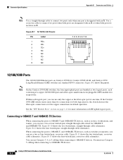
...a fiber-optic small form-factor pluggable (SFP) module slot, respectively. If the Catalyst 2950 LRE switch senses more information on Catalyst 2950T-24, Catalyst 2950T-48-SI, and Catalyst 2950 Long-Reach Ethernet (LRE) switches use a two or four twisted-pair, straight-through cable schematics. Figure B-10 ...or four twisted-pair, crossover cable. Use a crossover cable to 10BASE-T- Figure B-2 shows the pinout. Note On the Catalyst 2950 LRE switches, the four input uplink ports are designated with an X. Figure B-12 shows the four twisted-pair, straight-through cable...
...a fiber-optic small form-factor pluggable (SFP) module slot, respectively. If the Catalyst 2950 LRE switch senses more information on Catalyst 2950T-24, Catalyst 2950T-48-SI, and Catalyst 2950 Long-Reach Ethernet (LRE) switches use a two or four twisted-pair, straight-through cable schematics. Figure B-10 ...or four twisted-pair, crossover cable. Use a crossover cable to 10BASE-T- Figure B-2 shows the pinout. Note On the Catalyst 2950 LRE switches, the four input uplink ports are designated with an X. Figure B-12 shows the four twisted-pair, straight-through cable...

