
Hardware Installation Guide
Page 22
..., it supports only full-duplex mode. - Catalyst 2950SX-24 switch-24 10/100 Ethernet ports and 2 1000BASE-SX ports - For 10/100 ports, autonegotiates the speed and duplex settings - When the switch is running at 10 or 100 Mbps. Supports 8192 MAC addresses - For 10/100/1000 ports on the Catalyst 2950T-24 switch, autonegotiates the speed and supports only...
..., it supports only full-duplex mode. - Catalyst 2950SX-24 switch-24 10/100 Ethernet ports and 2 1000BASE-SX ports - For 10/100 ports, autonegotiates the speed and duplex settings - When the switch is running at 10 or 100 Mbps. Supports 8192 MAC addresses - For 10/100/1000 ports on the Catalyst 2950T-24 switch, autonegotiates the speed and supports only...
Hardware Installation Guide
Page 27
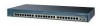
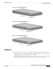
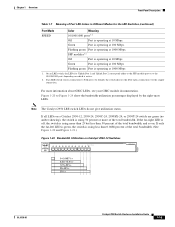
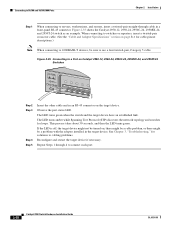
The ports can use RJ-45 connectors and twisted-pair cabling. OL-6156-01 Catalyst 2950 Switch Hardware Installation Guide 1-7 Chapter 1 Overview Figure 1-12 Catalyst 2950T-24 Switch Front-Panel Description 47337 SYST RPS STAT UTIL DUPLX SPEED MODE 1x 2x 3x 4x 5x 6x 7x 8x 9x 10x 11x 10Base-T... / 100Base-TX 12x 13x 14x 15x 16x 17x 18x 19x 20x 21x 22x 23x Catalyst 2950 SERIES 24x 10/100/100Base-T 1 2 10/100 ports 10/100/1000 ports Figure 1-13 Catalyst 2950SX-48-SI Switch 97630 SYST RPS STAT UTIL DUPLX SPEED MODE 1 1X 2X 23 45 67 8 9 10...
The ports can use RJ-45 connectors and twisted-pair cabling. OL-6156-01 Catalyst 2950 Switch Hardware Installation Guide 1-7 Chapter 1 Overview Figure 1-12 Catalyst 2950T-24 Switch Front-Panel Description 47337 SYST RPS STAT UTIL DUPLX SPEED MODE 1x 2x 3x 4x 5x 6x 7x 8x 9x 10x 11x 10Base-T... / 100Base-TX 12x 13x 14x 15x 16x 17x 18x 19x 20x 21x 22x 23x Catalyst 2950 SERIES 24x 10/100/100Base-T 1 2 10/100 ports 10/100/1000 ports Figure 1-13 Catalyst 2950SX-48-SI Switch 97630 SYST RPS STAT UTIL DUPLX SPEED MODE 1 1X 2X 23 45 67 8 9 10...
Hardware Installation Guide
Page 28
... be explicitly set to the "Identifying a Crossover Cable" section on Catalyst 2950T-24, Catalyst 2950T-48-SI, and Catalyst 2950 LRE switches use a twisted-pair crossover cable. In all cases, the cable length from a switch to hubs or other switches, use RJ-45 connectors and twisted-pair cabling. If the attached ...through cable. For information on how to identify a crossover cable, go to the "Identifying a Crossover Cable" section on the Catalyst 2950T-24 switch can be set to operate at 10 or 100 Mbps in full-duplex mode. When set for the cables are described in Appendix...
... be explicitly set to the "Identifying a Crossover Cable" section on Catalyst 2950T-24, Catalyst 2950T-48-SI, and Catalyst 2950 LRE switches use a twisted-pair crossover cable. In all cases, the cable length from a switch to hubs or other switches, use RJ-45 connectors and twisted-pair cabling. If the attached ...through cable. For information on how to identify a crossover cable, go to the "Identifying a Crossover Cable" section on the Catalyst 2950T-24 switch can be set to operate at 10 or 100 Mbps in full-duplex mode. When set for the cables are described in Appendix...

Hardware Installation Guide
Page 33
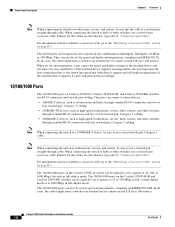
... you use to monitor individual switches and switch clusters. Figure 1-15 LEDs on Catalyst 2950-12, 2950-24, 2950C-24, 2950SX-24, and 2950T-24 Switches RPS LED Port status LEDs System...Catalyst 2950-12, 2950-24, 2950C-24, 2950SX-24, and 2950T-24 switches • Figure 1-16 for the Catalyst 2950G-12-EI, 2950G-24-EI, and 2950G-24-EI-DC switches • Figure 1-17 for the Catalyst 2950G-48-EI, Catalyst 2950SX-48-SI, and Catalyst 2950T-48-SI switches • Figure 1-18 for the Catalyst 2950ST-8 LRE and 2950ST-24 LRE switches • Figure 1-19 for the Catalyst 2950ST-24 LRE 997 switches...
... you use to monitor individual switches and switch clusters. Figure 1-15 LEDs on Catalyst 2950-12, 2950-24, 2950C-24, 2950SX-24, and 2950T-24 Switches RPS LED Port status LEDs System...Catalyst 2950-12, 2950-24, 2950C-24, 2950SX-24, and 2950T-24 switches • Figure 1-16 for the Catalyst 2950G-12-EI, 2950G-24-EI, and 2950G-24-EI-DC switches • Figure 1-17 for the Catalyst 2950G-48-EI, Catalyst 2950SX-48-SI, and Catalyst 2950T-48-SI switches • Figure 1-18 for the Catalyst 2950ST-8 LRE and 2950ST-24 LRE switches • Figure 1-19 for the Catalyst 2950ST-24 LRE 997 switches...
Hardware Installation Guide
Page 34
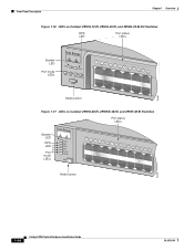
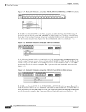
..., 2950G-24-EI, and 2950G-24-EI-DC Switches RPS LED Port status LEDs 65395 System LED Port mode LEDs SYST RPS STAT UTIL DUPLX SPEED MODE 1 1X 23 45 67 8 9 10 11 12 11X 2X 12X Mode button Figure 1-17 LEDs on Catalyst 2950G-48-EI, 2950SX-48-SI, and 2950T-48-SI Switches Port status... LEDs System LED RPS LED Port mode LEDs SYST RPS STAT UTIL DUPLX SPEED MODE 1 1X 23 45 67 89 10 11 12 13 14 15 16 15X 2X 16X Mode button 65508 1-14 Catalyst 2950 Switch Hardware Installation Guide...
..., 2950G-24-EI, and 2950G-24-EI-DC Switches RPS LED Port status LEDs 65395 System LED Port mode LEDs SYST RPS STAT UTIL DUPLX SPEED MODE 1 1X 23 45 67 8 9 10 11 12 11X 2X 12X Mode button Figure 1-17 LEDs on Catalyst 2950G-48-EI, 2950SX-48-SI, and 2950T-48-SI Switches Port status... LEDs System LED RPS LED Port mode LEDs SYST RPS STAT UTIL DUPLX SPEED MODE 1 1X 23 45 67 89 10 11 12 13 14 15 16 15X 2X 16X Mode button 65508 1-14 Catalyst 2950 Switch Hardware Installation Guide...
Hardware Installation Guide
Page 39
... Port is operating at 1000 Mbps. If all LEDs on a Catalyst 2950-12, 2950-24, 2950C-24, 2950SX-24, or 2950T-24 switch are green (no amber showing), the switch is operating at 10 Mbps. Figure 1-20 to Figure 1-24 show the bandwidth utilization percentages displayed by default, the switch chooses the fiber-optic connection over the copper connection. Note The...
... Port is operating at 1000 Mbps. If all LEDs on a Catalyst 2950-12, 2950-24, 2950C-24, 2950SX-24, or 2950T-24 switch are green (no amber showing), the switch is operating at 10 Mbps. Figure 1-20 to Figure 1-24 show the bandwidth utilization percentages displayed by default, the switch chooses the fiber-optic connection over the copper connection. Note The...
Hardware Installation Guide
Page 40
... using more than 25 but less than 50 percent of the total bandwidth. Front-Panel Description Chapter 1 Overview Figure 1-21 Bandwidth Utilization on Catalyst 2950-24, 2950C-24, 2950SX-24, and 2950T-24 Switches SYST RPS STAT UTIL DUPLX SPEED MODE 1x 2x 3x 4x 5x 6x 7x 8x 10Base-T / 100Base-TX 9x 10x 11x 12x 13x 14x...
... using more than 25 but less than 50 percent of the total bandwidth. Front-Panel Description Chapter 1 Overview Figure 1-21 Bandwidth Utilization on Catalyst 2950-24, 2950C-24, 2950SX-24, and 2950T-24 Switches SYST RPS STAT UTIL DUPLX SPEED MODE 1x 2x 3x 4x 5x 6x 7x 8x 10Base-T / 100Base-TX 9x 10x 11x 12x 13x 14x...

Hardware Installation Guide
Page 41
... Fan exhaust CONSOLE RJ-45 console port OL-6156-01 Catalyst 2950 Switch Hardware Installation Guide 1-21 Chapter 1 Overview Rear-Panel Description Figure 1-24 Bandwidth Utilization on Catalyst 2950G-48-EI, 2950SX-48-SI, and 2950T-48-SI Switches 65510 Catalyst 2950 12 1X 3 24 56 78 9 10 11 12 13 14 15 16 15X... 17 18 17X 19 20 21 22 23 24 25 26 27 28 29 31 31 ...
... Fan exhaust CONSOLE RJ-45 console port OL-6156-01 Catalyst 2950 Switch Hardware Installation Guide 1-21 Chapter 1 Overview Rear-Panel Description Figure 1-24 Bandwidth Utilization on Catalyst 2950G-48-EI, 2950SX-48-SI, and 2950T-48-SI Switches 65510 Catalyst 2950 12 1X 3 24 56 78 9 10 11 12 13 14 15 16 15X... 17 18 17X 19 20 21 22 23 24 25 26 27 28 29 31 31 ...
Hardware Installation Guide
Page 53
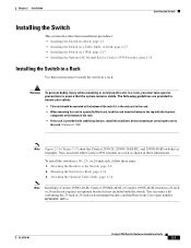
...; When mounting this unit in a partially filled rack, load the rack from Cisco (part number RCKMNT-1RU=). Attaching the Optional Cable Guide, page 2-16 Note Installing a Catalyst 2950G-48-EI, Catalyst 2950SX-48-SI, or Catalyst 2950T-48-SI switch in a 23-inch or 24-inch rack requires an optional bracket kit not included with stabilizing devices, install...
...; When mounting this unit in a partially filled rack, load the rack from Cisco (part number RCKMNT-1RU=). Attaching the Optional Cable Guide, page 2-16 Note Installing a Catalyst 2950G-48-EI, Catalyst 2950SX-48-SI, or Catalyst 2950T-48-SI switch in a 23-inch or 24-inch rack requires an optional bracket kit not included with stabilizing devices, install...
Hardware Installation Guide
Page 54
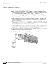
... number RCKMNT-1RU=) to the opposite side of the switch. or 24-inch bracket to the switch. See Figure 2-7, Figure 2-8, and Figure 2-9. • When mounting a switch other than a Catalyst 2950G-48-EI, Catalyst 2950SX-48-SI, or Catalyst 2950T-48-SI switch in a 24-inch rack, use depend on the Switch in a 24-inch rack, use two Phillips flat-head screws to the...
... number RCKMNT-1RU=) to the opposite side of the switch. or 24-inch bracket to the switch. See Figure 2-7, Figure 2-8, and Figure 2-9. • When mounting a switch other than a Catalyst 2950G-48-EI, Catalyst 2950SX-48-SI, or Catalyst 2950T-48-SI switch in a 24-inch rack, use depend on the Switch in a 24-inch rack, use two Phillips flat-head screws to the...
Hardware Installation Guide
Page 57
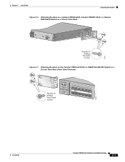
Chapter 2 Installation Installing the Switch Figure 2-6 Attaching Brackets on a Catalyst 2950G-48-EI, Catalyst 2950SX-48-SI, or Catalyst 2950T-48-SI Switch in a 19-Inch Telco Rack CONSOLE 65514 Number-8 Phillips flat-head screws Figure 2-7 Attaching Brackets on the Catalyst 2950G-24-EI-DC or 2950ST-24 LRE 997 Switch in a 23-Inch Telco Rack (Front Panel Forward) Number-8 Phillips truss-head screws SYST RPS STAT UTIL DUPLX SPEED MODE 1 1X 23 45 67 8 9 10 11 12 11X 2X 12X 65673 OL-6156-01 Catalyst 2950 Switch Hardware Installation Guide 2-11
Chapter 2 Installation Installing the Switch Figure 2-6 Attaching Brackets on a Catalyst 2950G-48-EI, Catalyst 2950SX-48-SI, or Catalyst 2950T-48-SI Switch in a 19-Inch Telco Rack CONSOLE 65514 Number-8 Phillips flat-head screws Figure 2-7 Attaching Brackets on the Catalyst 2950G-24-EI-DC or 2950ST-24 LRE 997 Switch in a 23-Inch Telco Rack (Front Panel Forward) Number-8 Phillips truss-head screws SYST RPS STAT UTIL DUPLX SPEED MODE 1 1X 23 45 67 8 9 10 11 12 11X 2X 12X 65673 OL-6156-01 Catalyst 2950 Switch Hardware Installation Guide 2-11
Hardware Installation Guide
Page 60
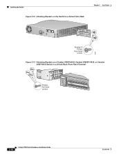
Installing the Switch Figure 2-12 Attaching Brackets on the Switch in a 24-Inch Telco Rack Chapter 2 Installation CONSOLE 65667 Number-8 Phillips truss-head screws Figure 2-13 Attaching Brackets on a Catalyst 2950G-48-EI, Catalyst 2950SX-48-SI, or Catalyst 2950T-48-SI Switch in a 24-Inch Rack (Front Panel Forward) Phillips flat-head screws SYST RPS STAT UTIL DUPLX SPEED MODE 1 1X 23 45 67 8 9 10 11 12 13 14 15 16 15X 2X 16X 74528 2-14 Catalyst 2950 Switch Hardware Installation Guide OL-6156-01
Installing the Switch Figure 2-12 Attaching Brackets on the Switch in a 24-Inch Telco Rack Chapter 2 Installation CONSOLE 65667 Number-8 Phillips truss-head screws Figure 2-13 Attaching Brackets on a Catalyst 2950G-48-EI, Catalyst 2950SX-48-SI, or Catalyst 2950T-48-SI Switch in a 24-Inch Rack (Front Panel Forward) Phillips flat-head screws SYST RPS STAT UTIL DUPLX SPEED MODE 1 1X 23 45 67 8 9 10 11 12 13 14 15 16 15X 2X 16X 74528 2-14 Catalyst 2950 Switch Hardware Installation Guide OL-6156-01
Hardware Installation Guide
Page 61
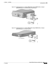
Chapter 2 Installation Installing the Switch Figure 2-14 Attaching Brackets on a Catalyst 2950G-48-EI, Catalyst 2950SX-48-SI, or Catalyst 2950T-48-SI Switch in a 24-Inch Rack (Rear Panel Forward) CONSOLE 74529 Phillips flat-head screws Figure 2-15 Attaching Brackets on a Catalyst 2950G-48-EI, Catalyst 2950SX-48-SI, or Catalyst 2950T-48-SI Switch in a 24-Inch Telco Rack 33 34 35 36 37 38 39 40 41 42 43 44 45 46 47 48 47X 48X Catalyst 2950 SERIES 1 2 24" Configuration Phillips flat-head screws 74530 OL-6156-01 Catalyst 2950 Switch Hardware Installation Guide 2-15
Chapter 2 Installation Installing the Switch Figure 2-14 Attaching Brackets on a Catalyst 2950G-48-EI, Catalyst 2950SX-48-SI, or Catalyst 2950T-48-SI Switch in a 24-Inch Rack (Rear Panel Forward) CONSOLE 74529 Phillips flat-head screws Figure 2-15 Attaching Brackets on a Catalyst 2950G-48-EI, Catalyst 2950SX-48-SI, or Catalyst 2950T-48-SI Switch in a 24-Inch Telco Rack 33 34 35 36 37 38 39 40 41 42 43 44 45 46 47 48 47X 48X Catalyst 2950 SERIES 1 2 24" Configuration Phillips flat-head screws 74530 OL-6156-01 Catalyst 2950 Switch Hardware Installation Guide 2-15
Hardware Installation Guide
Page 73
...port and a fiber-optic SFP module slot, respectively. Caution The Catalyst 2950G-24-EI-DC or Catalyst 2950ST-24 LRE 997 switch is suitable only for both ends. or full-duplex mode. When connecting the ports on Catalyst 2950T-24 switches operate at 10, 100, or 1000 Mbps in either half- These... ports on the Catalyst 2950G-24-EI-DC and Catalyst 2950ST-24 LRE 997 switches to other devices, follow your normal board and component handling procedures...
...port and a fiber-optic SFP module slot, respectively. Caution The Catalyst 2950G-24-EI-DC or Catalyst 2950ST-24 LRE 997 switch is suitable only for both ends. or full-duplex mode. When connecting the ports on Catalyst 2950T-24 switches operate at 10, 100, or 1000 Mbps in either half- These... ports on the Catalyst 2950G-24-EI-DC and Catalyst 2950ST-24 LRE 997 switches to other devices, follow your normal board and component handling procedures...
Hardware Installation Guide
Page 74
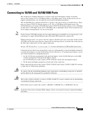
...solutions to cabling problems. Reconfigure and restart the target device if necessary. Figure 2-35 Connecting to a Port on Catalyst 2950-12, 2950-24, 2950C-24, 2950SX-24, and 2950T-24 Switches SYST RPS STAT UTIL DUPLX SPEED MODE 1x 2x 3x 4x 5x 45576 Step 2 Step 3 Step 4 Step...to use a four twisted-pair, Category 5 cable. See Chapter 3, "Troubleshooting," for loops. Figure 2-35 shows the Catalyst 2950-12, 2950-24, 2950C-24, 2950SX-24, and 2950T-24 switch as an example. Connecting to 10/100 and 10/100/1000 Ports Chapter 2 Installation Step 1 When connecting to servers, ...
...solutions to cabling problems. Reconfigure and restart the target device if necessary. Figure 2-35 Connecting to a Port on Catalyst 2950-12, 2950-24, 2950C-24, 2950SX-24, and 2950T-24 Switches SYST RPS STAT UTIL DUPLX SPEED MODE 1x 2x 3x 4x 5x 45576 Step 2 Step 3 Step 4 Step...to use a four twisted-pair, Category 5 cable. See Chapter 3, "Troubleshooting," for loops. Figure 2-35 shows the Catalyst 2950-12, 2950-24, 2950C-24, 2950SX-24, and 2950T-24 switch as an example. Connecting to 10/100 and 10/100/1000 Ports Chapter 2 Installation Step 1 When connecting to servers, ...

Hardware Installation Guide
Page 91
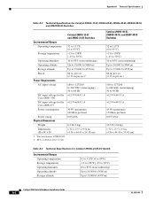
... Table A-10 lists the regulatory agency approval only for the switches other than the Catalyst 2950 Long-Reach Ethernet (LRE) switches. Table A-1 Technical Specifications for Catalyst 2950-12, 2950-24, 2950C-24, 2950SX-24, and 2950T-24 Switches Environmental Ranges Operating temperature 32 to 113°F (0 to... agency approvals for the Catalyst 2950 switches. A A P P E N D I X Technical Specifications OL-6156-01 Table A-1 through Table A-5 list the technical specifications for the Catalyst 2950 LRE switches. Table A-6 lists the technical specifications for the Cisco RPS 675 +12 V...
... Table A-10 lists the regulatory agency approval only for the switches other than the Catalyst 2950 Long-Reach Ethernet (LRE) switches. Table A-1 Technical Specifications for Catalyst 2950-12, 2950-24, 2950C-24, 2950SX-24, and 2950T-24 Switches Environmental Ranges Operating temperature 32 to 113°F (0 to... agency approvals for the Catalyst 2950 switches. A A P P E N D I X Technical Specifications OL-6156-01 Table A-1 through Table A-5 list the technical specifications for the Catalyst 2950 LRE switches. Table A-6 lists the technical specifications for the Cisco RPS 675 +12 V...
Hardware Installation Guide
Page 92
... A Cisco RPS 675 Power consumption 30 W (maximum) 102 Btus per hour 0.075 kVA 10.5 lb (4.8 kg) 1.72 x 17.5 x 13 in. (4.36 x 44.45 x 33.02 cm) Table A-3 Technical Specifications for Catalyst 2950G-12-EI, 2950G-24-EI, 2950G-48-EI, 2950SX-48-SI, and 2950T-48-SI Switches Catalyst 2950G-12-EI and 2950G-24-EI Switches Environmental...Up to 10,000 ft (3000 m) Storage altitude Up to 15,000 ft (4570 m) 84 in. RPS = redundant power system Catalyst 2950G-48-EI, 2950SX-48-SI, and 2950T-48-SI Switches 32 to 113°F (0 to 45°C) -13 to 158°F (-25 to 70°C) 10 to 85% (noncondensing)...
... A Cisco RPS 675 Power consumption 30 W (maximum) 102 Btus per hour 0.075 kVA 10.5 lb (4.8 kg) 1.72 x 17.5 x 13 in. (4.36 x 44.45 x 33.02 cm) Table A-3 Technical Specifications for Catalyst 2950G-12-EI, 2950G-24-EI, 2950G-48-EI, 2950SX-48-SI, and 2950T-48-SI Switches Catalyst 2950G-12-EI and 2950G-24-EI Switches Environmental...Up to 10,000 ft (3000 m) Storage altitude Up to 15,000 ft (4570 m) 84 in. RPS = redundant power system Catalyst 2950G-48-EI, 2950SX-48-SI, and 2950T-48-SI Switches 32 to 113°F (0 to 45°C) -13 to 158°F (-25 to 70°C) 10 to 85% (noncondensing)...
Hardware Installation Guide
Page 100
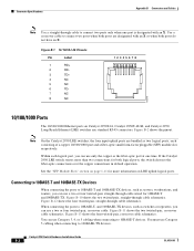
... a copper 10/100/1000 port and a fiber-optic small form-factor pluggable (SFP) module slot, respectively. If the Catalyst 2950 LRE switch senses more information on LRE uplink logical ports. Connecting to 10BASE-T and 100BASE-TX Devices When connecting the ports to 10BASE... the four twisted-pair, crossover cable schematics. Figure B-2 shows the pinout. See the "SFP Module Slots" section on Catalyst 2950T-24, Catalyst 2950T-48-SI, and Catalyst 2950 Long-Reach Ethernet (LRE) switches use a two or four twisted-pair, crossover cable. You must use Category 3, 4, or 5 cabling when connecting to...
... a copper 10/100/1000 port and a fiber-optic small form-factor pluggable (SFP) module slot, respectively. If the Catalyst 2950 LRE switch senses more information on LRE uplink logical ports. Connecting to 10BASE-T and 100BASE-TX Devices When connecting the ports to 10BASE... the four twisted-pair, crossover cable schematics. Figure B-2 shows the pinout. See the "SFP Module Slots" section on Catalyst 2950T-24, Catalyst 2950T-48-SI, and Catalyst 2950 Long-Reach Ethernet (LRE) switches use a two or four twisted-pair, crossover cable. You must use Category 3, 4, or 5 cabling when connecting to...

Hardware Installation Guide
Page 106
...+ 2 TP03 TP1+ 6 TP1- 4 TP2+ 5 TP27 TP3+ 8 TP3- 4 TP2+ 5 TP27 TP3+ 8 TP3- 65274 RJ-21 Cable Pinouts Table B-1 lists the RJ-21 cable pinouts on Catalyst 2950T-24 switches, Catalyst 2950 LRE switches, and 1000BASE-T GBIC module ports. Router or PC 1 TP1+ 2 TP13 TPO+ 6 TPO- 4 TP2+ 5 TP27 TP3+ 8 TP3- 4 TP3+ 5 TP37 TP2+ 8 TP2- 65272 Figure B-15 Four...
...+ 2 TP03 TP1+ 6 TP1- 4 TP2+ 5 TP27 TP3+ 8 TP3- 4 TP2+ 5 TP27 TP3+ 8 TP3- 65274 RJ-21 Cable Pinouts Table B-1 lists the RJ-21 cable pinouts on Catalyst 2950T-24 switches, Catalyst 2950 LRE switches, and 1000BASE-T GBIC module ports. Router or PC 1 TP1+ 2 TP13 TPO+ 6 TPO- 4 TP2+ 5 TP27 TP3+ 8 TP3- 4 TP3+ 5 TP37 TP2+ 8 TP2- 65272 Figure B-15 Four...
