
Hardware Installation Guide
Page 43
...-AC-US= DC Power Connector The Catalyst 2950G-24-EI-DC and Catalyst 2950ST-24 LRE 997 switches have an internal DC-power converter. Cisco RPS Connector Specific Cisco RPS models support specific Catalyst 2950 switches: • Cisco RPS 300 (model PWR300-AC-RPS-N1) • Cisco RPS 675 (model PWR675-AC-RPS-N1=) Cisco RPS 300 The Cisco RPS 300 has two output levels: -48...
...-AC-US= DC Power Connector The Catalyst 2950G-24-EI-DC and Catalyst 2950ST-24 LRE 997 switches have an internal DC-power converter. Cisco RPS Connector Specific Cisco RPS models support specific Catalyst 2950 switches: • Cisco RPS 300 (model PWR300-AC-RPS-N1) • Cisco RPS 675 (model PWR675-AC-RPS-N1=) Cisco RPS 300 The Cisco RPS 300 has two output levels: -48...
Hardware Installation Guide
Page 44
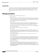
...with Cisco Network Assistant guide and the Network Assistant online help. • Device Manager You can use Network Assistant to perform basic switch configuration and monitoring. For more information, see the "Cable and Adapter Specifications" section on page B-6. Management Options Catalyst 2950 switches ...go to Appendix D, "Configuring the Switch with your network, you need a web browser to the console port on your desktop; To launch the Device Manager, enter the switch IP address in your SNMP application. 1-24 Catalyst 2950 Switch Hardware Installation Guide OL-6156-01
...with Cisco Network Assistant guide and the Network Assistant online help. • Device Manager You can use Network Assistant to perform basic switch configuration and monitoring. For more information, see the "Cable and Adapter Specifications" section on page B-6. Management Options Catalyst 2950 switches ...go to Appendix D, "Configuring the Switch with your network, you need a web browser to the console port on your desktop; To launch the Device Manager, enter the switch IP address in your SNMP application. 1-24 Catalyst 2950 Switch Hardware Installation Guide OL-6156-01

Hardware Installation Guide
Page 51
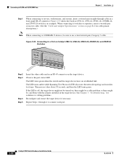
...specifications vary. Front-panel LEDs can be connected with the Catalyst 2950G-24-EI-DC switch or the Catalyst 2950ST-24 LRE 997 switch) • Console cable • Mounting kit containing these conditions: - If any item is within reach of an AC power outlet. - The switch is shipped with these items: • Catalyst 2950 Switch... around it might be greater than the LRE switches is missing or damaged, contact your Cisco representative or reseller for support. Note If the switch is installed in Appendix A, "Technical Specifications." • Clearance to Telcordia GR-1089-CORE...
...specifications vary. Front-panel LEDs can be connected with the Catalyst 2950G-24-EI-DC switch or the Catalyst 2950ST-24 LRE 997 switch) • Console cable • Mounting kit containing these conditions: - If any item is within reach of an AC power outlet. - The switch is shipped with these items: • Catalyst 2950 Switch... around it might be greater than the LRE switches is missing or damaged, contact your Cisco representative or reseller for support. Note If the switch is installed in Appendix A, "Technical Specifications." • Clearance to Telcordia GR-1089-CORE...
Hardware Installation Guide
Page 74
... Specifications" section on the target device. Figure 2-35 shows the Catalyst 2950-12, 2950-24, 2950C-24, 2950SX-24, and 2950T-24 switch as an example. The LED turns amber while Spanning Tree Protocol (STP) discovers the network topology and searches for loops. If the LED is off, the target device might not be turned on Catalyst 2950-12, 2950-24, 2950C-24, 2950SX-24, and 2950T-24 Switches...
... Specifications" section on the target device. Figure 2-35 shows the Catalyst 2950-12, 2950-24, 2950C-24, 2950SX-24, and 2950T-24 switch as an example. The LED turns amber while Spanning Tree Protocol (STP) discovers the network topology and searches for loops. If the LED is off, the target device might not be turned on Catalyst 2950-12, 2950-24, 2950C-24, 2950SX-24, and 2950T-24 Switches...
Hardware Installation Guide
Page 77
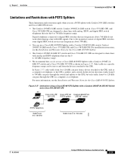
...CPE, such as shown in a specific frequency range can be sent to and from 0 to 120 kHz can pass through the CPE to a computer or a telephone. In the reverse direction, traffic from 0 to 700 kHz can pass through the switch and splitter to the CPE, but... with POTS Splitters These limitations and restrictions apply when you use a POTS splitter with Catalyst 2950 LRE switches and Cisco LRE CPE devices: • The Catalyst 2950ST-8 LRE switch, Catalyst 2950ST-24 LRE switch, Cisco 575 LRE CPE, and Cisco 585 LRE CPE are designed to share lines with analog and ISDN telephones that use ...
...CPE, such as shown in a specific frequency range can be sent to and from 0 to 120 kHz can pass through the CPE to a computer or a telephone. In the reverse direction, traffic from 0 to 700 kHz can pass through the switch and splitter to the CPE, but... with POTS Splitters These limitations and restrictions apply when you use a POTS splitter with Catalyst 2950 LRE switches and Cisco LRE CPE devices: • The Catalyst 2950ST-8 LRE switch, Catalyst 2950ST-24 LRE switch, Cisco 575 LRE CPE, and Cisco 585 LRE CPE are designed to share lines with analog and ISDN telephones that use ...

Hardware Installation Guide
Page 91
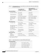
... approvals for the Cisco RPS 675 +12 V @4.5 A Power consumption 30 W (maximum) 102 Btus per hour Power rating Physical Dimensions 0.05 kVA Weight 6.5 lb (3 kg) Dimensions (H x W x D) 1.72 x 17.5 x 9.52 in . Table A-1 Technical Specifications for the Catalyst 2950 switches. A A P P E N D I X Technical Specifications OL-6156-01 Table A-1 through Table A-5 list the technical specifications for Catalyst 2950-12, 2950-24, 2950C-24, 2950SX-24, and 2950T-24 Switches Environmental Ranges Operating...
... approvals for the Cisco RPS 675 +12 V @4.5 A Power consumption 30 W (maximum) 102 Btus per hour Power rating Physical Dimensions 0.05 kVA Weight 6.5 lb (3 kg) Dimensions (H x W x D) 1.72 x 17.5 x 9.52 in . Table A-1 Technical Specifications for the Catalyst 2950 switches. A A P P E N D I X Technical Specifications OL-6156-01 Table A-1 through Table A-5 list the technical specifications for Catalyst 2950-12, 2950-24, 2950C-24, 2950SX-24, and 2950T-24 Switches Environmental Ranges Operating...
Hardware Installation Guide
Page 92
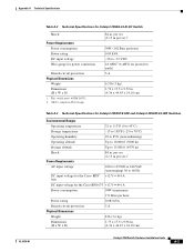
... 10,000 ft (3000 m) Up to 15,000 ft (4570 m) Catalyst 2950 Switch Hardware Installation Guide A-2 OL-6156-01 This switch meets ASTM D3332. 2. RPS = redundant power system Catalyst 2950G-48-EI, 2950SX-48-SI, and 2950T-48-SI Switches 32 to 113°F (0 to 45°C) -13 to 158°...Cisco RPS 675 Power consumption 30 W (maximum) 102 Btus per hour 0.075 kVA 10.5 lb (4.8 kg) 1.72 x 17.5 x 13 in. (4.36 x 44.45 x 33.02 cm) Table A-3 Technical Specifications for Catalyst 2950G-12-EI, 2950G-24-EI, 2950G-48-EI, 2950SX-48-SI, and 2950T-48-SI Switches Catalyst 2950G-12-EI and 2950G-24-EI Switches...
... 10,000 ft (3000 m) Up to 15,000 ft (4570 m) Catalyst 2950 Switch Hardware Installation Guide A-2 OL-6156-01 This switch meets ASTM D3332. 2. RPS = redundant power system Catalyst 2950G-48-EI, 2950SX-48-SI, and 2950T-48-SI Switches 32 to 113°F (0 to 45°C) -13 to 158°...Cisco RPS 675 Power consumption 30 W (maximum) 102 Btus per hour 0.075 kVA 10.5 lb (4.8 kg) 1.72 x 17.5 x 13 in. (4.36 x 44.45 x 33.02 cm) Table A-3 Technical Specifications for Catalyst 2950G-12-EI, 2950G-24-EI, 2950G-48-EI, 2950SX-48-SI, and 2950T-48-SI Switches Catalyst 2950G-12-EI and 2950G-24-EI Switches...
Hardware Installation Guide
Page 93
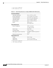
... = American Wire Gauge 84 in . (4.36 x 44.45 x 24.18 cm) Catalyst 2950 Switch Hardware Installation Guide A-3 per sec (2.13 m per sec)1 Power Requirements AC input voltage DC input voltage for the Cisco RPS2 300 100 to 127/200 to 240 VAC (autoranging) 50 to...Dimensions Weight Dimensions (H x W x D) 1. This switch meets ASTM D3332. 2. Appendix A Technical Specifications OL-6156-01 Table A-3 Technical Specifications for Catalyst 2950G-24-EI-DC Switch Shock Power Requirements Power consumption Power rating DC input voltage Wire gauge for the Cisco RPS 675 +12 V @4 A Power consumption 50W...
... = American Wire Gauge 84 in . (4.36 x 44.45 x 24.18 cm) Catalyst 2950 Switch Hardware Installation Guide A-3 per sec (2.13 m per sec)1 Power Requirements AC input voltage DC input voltage for the Cisco RPS2 300 100 to 127/200 to 240 VAC (autoranging) 50 to...Dimensions Weight Dimensions (H x W x D) 1. This switch meets ASTM D3332. 2. Appendix A Technical Specifications OL-6156-01 Table A-3 Technical Specifications for Catalyst 2950G-24-EI-DC Switch Shock Power Requirements Power consumption Power rating DC input voltage Wire gauge for the Cisco RPS 675 +12 V @4 A Power consumption 50W...
Hardware Installation Guide
Page 94
... Physical Dimensions Weight Dimensions (H x W x D) 1. RPS = redundant power system Table A-5 Technical Specifications for Catalyst-2950ST-24 997 LRE Switches Environmental Ranges Operating temperature Storage temperature Operating humidity Operating altitude Storage altitude Shock Power Requirements Power consumption Power ...9.96 in . This switch meets ASTM D3332. 2. This switch meets ASTM D3332. 2. per sec (2.13 m per sec)1 50W (maximum) 171 Btus per hour 0.083 kVA -36 to 15,000 ft (4570 m) 84 in . (4.36 x 44.45 x 24.18 cm) Catalyst 2950 Switch Hardware Installation Guide A-4...
... Physical Dimensions Weight Dimensions (H x W x D) 1. RPS = redundant power system Table A-5 Technical Specifications for Catalyst-2950ST-24 997 LRE Switches Environmental Ranges Operating temperature Storage temperature Operating humidity Operating altitude Storage altitude Shock Power Requirements Power consumption Power ...9.96 in . This switch meets ASTM D3332. 2. This switch meets ASTM D3332. 2. per sec (2.13 m per sec)1 50W (maximum) 171 Btus per hour 0.083 kVA -36 to 15,000 ft (4570 m) 84 in . (4.36 x 44.45 x 24.18 cm) Catalyst 2950 Switch Hardware Installation Guide A-4...
Hardware Installation Guide
Page 95
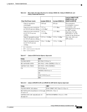
... pluggable 3. Optical transmitter power -20 to -14 dBm for 50/125-micron cabling Catalyst 2950SX-24 850 nm -13.5 dBm -12.5 dBm -9.5 to -4 dBm 1. Appendix A Technical Specifications Table A-6 Fiber-Optic Port Specifications for Catalyst 2950C-24, Catalyst 2950SX-24, and Catalyst 2950 LRE Switches Fiber-Port Power Levels Catalyst 2950C-24 Optical transmitter wavelength 1300 nm1 Optical receiver sensitivity -33.5 to for 50/125-micron...
... pluggable 3. Optical transmitter power -20 to -14 dBm for 50/125-micron cabling Catalyst 2950SX-24 850 nm -13.5 dBm -12.5 dBm -9.5 to -4 dBm 1. Appendix A Technical Specifications Table A-6 Fiber-Optic Port Specifications for Catalyst 2950C-24, Catalyst 2950SX-24, and Catalyst 2950 LRE Switches Fiber-Port Power Levels Catalyst 2950C-24 Optical transmitter wavelength 1300 nm1 Optical receiver sensitivity -33.5 to for 50/125-micron...

Hardware Installation Guide
Page 96
Appendix A Technical Specifications Table A-8 Catalyst 2950ST-8 LRE and 2950ST-24 LRE Switch Agency Approvals (continued) Safety EMC TUV-GS to EN60950 with Amendments EN 55024:..., and Short Voltage Interruptions AS/NZS 3548, Class A BSMI, Class A VCCI, Class A MIC Mark Table A-9 Catalyst 2950ST-24 LRE 997 Switch Agency Approvals Safety EMC UL/CSA 60950, 3rd edition USA CFR47, FCC, Part 15, Class A IEC 60950 with Amendments...11/IEC1000-4-11: Immunity to Voltage Dips, Voltage Variations, and Short Voltage Interruptions Catalyst 2950 Switch Hardware Installation Guide A-6 OL-6156-01
Appendix A Technical Specifications Table A-8 Catalyst 2950ST-8 LRE and 2950ST-24 LRE Switch Agency Approvals (continued) Safety EMC TUV-GS to EN60950 with Amendments EN 55024:..., and Short Voltage Interruptions AS/NZS 3548, Class A BSMI, Class A VCCI, Class A MIC Mark Table A-9 Catalyst 2950ST-24 LRE 997 Switch Agency Approvals Safety EMC UL/CSA 60950, 3rd edition USA CFR47, FCC, Part 15, Class A IEC 60950 with Amendments...11/IEC1000-4-11: Immunity to Voltage Dips, Voltage Variations, and Short Voltage Interruptions Catalyst 2950 Switch Hardware Installation Guide A-6 OL-6156-01

Hardware Installation Guide
Page 97
Appendix A Technical Specifications Table A-10 Catalyst 2950G-24-EI-DC Switch Agency Approvals NEBS Bellcore GR-1089-CORE Bellcore GR-63-CORE Bellcore SR-3580 Level 3 OL-6156-01 Catalyst 2950 Switch Hardware Installation Guide A-7
Appendix A Technical Specifications Table A-10 Catalyst 2950G-24-EI-DC Switch Agency Approvals NEBS Bellcore GR-1089-CORE Bellcore GR-63-CORE Bellcore SR-3580 Level 3 OL-6156-01 Catalyst 2950 Switch Hardware Installation Guide A-7
Hardware Installation Guide
Page 100
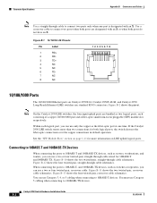
If the Catalyst 2950 LRE switch senses more information on Catalyst 2950T-24, Catalyst 2950T-48-SI, and Catalyst 2950 Long-Reach Ethernet (LRE) switches use Category 5 cabling when connecting to 100BASE-TX devices. Connecting to 10BASE-T and 100BASE-TX Devices When connecting... straight-through cable wired for more than two connections for both ports are bundled as switches or repeaters, you can use Category 3, 4, or 5 cabling when connecting to 10BASE-T devices. Connector Specifications Appendix B Connectors and Cables Note Use a straight-through cable to connect two ports ...
If the Catalyst 2950 LRE switch senses more information on Catalyst 2950T-24, Catalyst 2950T-48-SI, and Catalyst 2950 Long-Reach Ethernet (LRE) switches use Category 5 cabling when connecting to 100BASE-TX devices. Connecting to 10BASE-T and 100BASE-TX Devices When connecting... straight-through cable wired for more than two connections for both ports are bundled as switches or repeaters, you can use Category 3, 4, or 5 cabling when connecting to 10BASE-T devices. Connector Specifications Appendix B Connectors and Cables Note Use a straight-through cable to connect two ports ...

Hardware Installation Guide
Page 101
...pair, Category 5 cable when connecting to a 1000BASE-T device. Each LRE port uses two pins. Because the Catalyst 2950ST-24 LRE and Catalyst 2950ST-24 LRE 997 switches use 48 pins, pin 25 on the top row and pin 50 on the bottom row are not used The...1 97734 OL-6156-01 50 34 26 Catalyst 2950 Switch Hardware Installation Guide B-3 When connecting the ports to other devices, such as switches or repeaters, you must use a four twisted-pair, Category 5, crossover cable. Appendix B Connectors and Cables Connector Specifications Connecting to 1000BASE-T Devices When connecting the ...
...pair, Category 5 cable when connecting to a 1000BASE-T device. Each LRE port uses two pins. Because the Catalyst 2950ST-24 LRE and Catalyst 2950ST-24 LRE 997 switches use 48 pins, pin 25 on the top row and pin 50 on the bottom row are not used The...1 97734 OL-6156-01 50 34 26 Catalyst 2950 Switch Hardware Installation Guide B-3 When connecting the ports to other devices, such as switches or repeaters, you must use a four twisted-pair, Category 5, crossover cable. Appendix B Connectors and Cables Connector Specifications Connecting to 1000BASE-T Devices When connecting the ...

Hardware Installation Guide
Page 106
... B-1 lists the RJ-21 cable pinouts on Catalyst 2950T-24 switches, Catalyst 2950 LRE switches, and 1000BASE-T GBIC module ports. Figure B-14 Four Twisted-Pair Straight-Through Cable Schematic for 10/100/1000 and 1000BASE-T GBIC Module Ports Switch 1 TPO+ 2 TPO3 TP1+ 6 TP1- Table B-1 Catalyst 2950ST-24 LRE and Catalyst 2950ST-24 LRE 997 Switch RJ-21 Cable Pinouts Function Port 1 Tip...
... B-1 lists the RJ-21 cable pinouts on Catalyst 2950T-24 switches, Catalyst 2950 LRE switches, and 1000BASE-T GBIC module ports. Figure B-14 Four Twisted-Pair Straight-Through Cable Schematic for 10/100/1000 and 1000BASE-T GBIC Module Ports Switch 1 TPO+ 2 TPO3 TP1+ 6 TP1- Table B-1 Catalyst 2950ST-24 LRE and Catalyst 2950ST-24 LRE 997 Switch RJ-21 Cable Pinouts Function Port 1 Tip...

Hardware Installation Guide
Page 107
Appendix B Connectors and Cables Cable and Adapter Specifications Table B-1 Catalyst 2950ST-24 LRE and Catalyst 2950ST-24 LRE 997 Switch RJ-21 Cable Pinouts Function Pin Pin Function Port 5 Tip 5 30 Port 5 Ring Port 6 Tip 6 31 Port 6 Ring Port 7 Tip 7 32 Port 7 Ring Port 8 Tip 8 ... 6 Ring Port 7 Tip 7 32 Port 7 Ring Port 8 Tip 8 33 Port 8 Ring No connect 9 34 No connect No connect 10 35 No connect OL-6156-01 Catalyst 2950 Switch Hardware Installation Guide B-9
Appendix B Connectors and Cables Cable and Adapter Specifications Table B-1 Catalyst 2950ST-24 LRE and Catalyst 2950ST-24 LRE 997 Switch RJ-21 Cable Pinouts Function Pin Pin Function Port 5 Tip 5 30 Port 5 Ring Port 6 Tip 6 31 Port 6 Ring Port 7 Tip 7 32 Port 7 Ring Port 8 Tip 8 ... 6 Ring Port 7 Tip 7 32 Port 7 Ring Port 8 Tip 8 33 Port 8 Ring No connect 9 34 No connect No connect 10 35 No connect OL-6156-01 Catalyst 2950 Switch Hardware Installation Guide B-9

Hardware Installation Guide
Page 108
... RJ-45-to -DB-9 adapter cable, and the console device. Cable and Adapter Specifications Appendix B Connectors and Cables Table B-2 Catalyst 2950ST-8 LRE Switch RJ-21 Cable Pinouts (continued) Function Pin Pin Function No connect 11 36 No ...21 46 No connect No connect 22 47 No connect No connect 23 48 No connect No connect 24 49 No connect No connect 25 50 No connect Adapter Pinouts Table B-3 lists the pinouts for the... 5 5 RxD 6 3 Not connected 7 4 CTS 8 7 Console Device Signal CTS DSR RxD GND GND TxD DTR RTS B-10 Catalyst 2950 Switch Hardware Installation Guide OL-6156-01
... RJ-45-to -DB-9 adapter cable, and the console device. Cable and Adapter Specifications Appendix B Connectors and Cables Table B-2 Catalyst 2950ST-8 LRE Switch RJ-21 Cable Pinouts (continued) Function Pin Pin Function No connect 11 36 No ...21 46 No connect No connect 22 47 No connect No connect 23 48 No connect No connect 24 49 No connect No connect 25 50 No connect Adapter Pinouts Table B-3 lists the pinouts for the... 5 5 RxD 6 3 Not connected 7 4 CTS 8 7 Console Device Signal CTS DSR RxD GND GND TxD DTR RTS B-10 Catalyst 2950 Switch Hardware Installation Guide OL-6156-01
Hardware Installation Guide
Page 129
... connector 2-23 specifications A-2, A-4 warnings C-1 to C-4 desk-mounting 3-17 OL-6156-01 Index Device Manager xvi description 2-24 to configure switch 3-40 viewing LEDs 2-13 dimensions A-1 to A-4 documentation ordering xvii related publications xv to xvi URLs, Cisco xvii document conventions ... fan problems, solving 4-3 features 2-1 to 2-3 feedback to Cisco Systems, web xviii fiber-optic port specifications A-5 front panel 10/100/1000 ports 2-8 10/100 ports 2-7 to 2-8 1000BASE-SX ports 2-9 100BASE-FX ports 2-9 clearance 3-5 described 2-3 Catalyst 2950 Switch Hardware Installation Guide IN-3
... connector 2-23 specifications A-2, A-4 warnings C-1 to C-4 desk-mounting 3-17 OL-6156-01 Index Device Manager xvi description 2-24 to configure switch 3-40 viewing LEDs 2-13 dimensions A-1 to A-4 documentation ordering xvii related publications xv to xvi URLs, Cisco xvii document conventions ... fan problems, solving 4-3 features 2-1 to 2-3 feedback to Cisco Systems, web xviii fiber-optic port specifications A-5 front panel 10/100/1000 ports 2-8 10/100 ports 2-7 to 2-8 1000BASE-SX ports 2-9 100BASE-FX ports 2-9 clearance 3-5 described 2-3 Catalyst 2950 Switch Hardware Installation Guide IN-3

Hardware Installation Guide
Page 133
... ports, illustrated 2-5 shelf-mounting 3-17 SNMP network management platforms 2-24 software switch management 2-24 specifications A-1 to A-7 speed LED 2-17 to 2-19 status LED 2-...specifications A-1 to A-7 Telnet, and accessing the CLI 2-24 temperature operating A-1 to A-4 terminal-emulation software D-4 troubleshooting diagnosing problems 4-1 to 4-3 understanding POST results 4-1 OL-6156-01 Index U uplink ports, LRE 2-9 URLs, Cisco xvii utilization bandwidth 2-17 to 2-21 LED 2-17 V verifying package contents 3-5 to 3-6 W warnings DC power C-1 to C-4 installation 3-1 to 3-4 Catalyst 2950 Switch...
... ports, illustrated 2-5 shelf-mounting 3-17 SNMP network management platforms 2-24 software switch management 2-24 specifications A-1 to A-7 speed LED 2-17 to 2-19 status LED 2-...specifications A-1 to A-7 Telnet, and accessing the CLI 2-24 temperature operating A-1 to A-4 terminal-emulation software D-4 troubleshooting diagnosing problems 4-1 to 4-3 understanding POST results 4-1 OL-6156-01 Index U uplink ports, LRE 2-9 URLs, Cisco xvii utilization bandwidth 2-17 to 2-21 LED 2-17 V verifying package contents 3-5 to 3-6 W warnings DC power C-1 to C-4 installation 3-1 to 3-4 Catalyst 2950 Switch...


