Hardware Installation Guide
Page 4
... Cisco RPS Connector 1-23 Console Port 1-24 Management Options 1-24 Installation 2-1 Preparing for Installation 2-1 Warnings 2-1 Installation Guidelines 2-4 Verifying Package Contents 2-5 Verifying Switch Operation 2-6 Installing the Switch 2-7 Installing the Switch in a Rack 2-7 Attaching the Brackets to the Switch 2-8 Mounting the Switch in...Switch on a Table, Shelf, or Desk 2-17 Installing the Switch on a Wall 2-17 Attaching the Brackets to the Switch 2-17 Attaching the RPS Connector Cover 2-18 Mounting the Switch to a Wall 2-18 Installing the Optional AC Ground Kit for Catalyst 2950 Switches...
... Cisco RPS Connector 1-23 Console Port 1-24 Management Options 1-24 Installation 2-1 Preparing for Installation 2-1 Warnings 2-1 Installation Guidelines 2-4 Verifying Package Contents 2-5 Verifying Switch Operation 2-6 Installing the Switch 2-7 Installing the Switch in a Rack 2-7 Attaching the Brackets to the Switch 2-8 Mounting the Switch in...Switch on a Table, Shelf, or Desk 2-17 Installing the Switch on a Wall 2-17 Attaching the Brackets to the Switch 2-17 Attaching the RPS Connector Cover 2-18 Mounting the Switch to a Wall 2-18 Installing the Optional AC Ground Kit for Catalyst 2950 Switches...
Hardware Installation Guide
Page 21
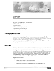
... Ethernet, and Long-Reach Ethernet (LRE) traffic from other switches. Catalyst 2950-24 switch-24 10/100 Ethernet ports - All models of Ethernet switches that show the Catalyst 2950 switches. See the switch software configuration guide for both AC- Catalyst 2950-12 switch-12 10/100 Ethernet ports - Catalyst 2950C-24 switch-24 10/100 Ethernet ports and 2 100BASE-FX ports OL-6156-01 Catalyst 2950 Switch Hardware Installation Guide 1-1 Figure 1-1 through Figure 1-12 show...
... Ethernet, and Long-Reach Ethernet (LRE) traffic from other switches. Catalyst 2950-24 switch-24 10/100 Ethernet ports - All models of Ethernet switches that show the Catalyst 2950 switches. See the switch software configuration guide for both AC- Catalyst 2950-12 switch-12 10/100 Ethernet ports - Catalyst 2950C-24 switch-24 10/100 Ethernet ports and 2 100BASE-FX ports OL-6156-01 Catalyst 2950 Switch Hardware Installation Guide 1-1 Figure 1-1 through Figure 1-12 show...

Hardware Installation Guide
Page 22
... or 100 Mbps. Catalyst 2950SX-24 switch-24 10/100 Ethernet ports and 2 1000BASE-SX ports - Catalyst 2950SX-48-SI switch-48 10/100 Ethernet ports and 2 1000BASE-SX ports - Features Chapter 1 Overview - For 10/100/1000 ports on the Catalyst 2950T-48-SI and 2950 LRE switches, autonegotiates the speed and duplex setting when operating at one time.) Note See the Catalyst 2950 LRE switch release notes for...
... or 100 Mbps. Catalyst 2950SX-24 switch-24 10/100 Ethernet ports and 2 1000BASE-SX ports - Catalyst 2950SX-48-SI switch-48 10/100 Ethernet ports and 2 1000BASE-SX ports - Features Chapter 1 Overview - For 10/100/1000 ports on the Catalyst 2950T-48-SI and 2950 LRE switches, autonegotiates the speed and duplex setting when operating at one time.) Note See the Catalyst 2950 LRE switch release notes for...

Hardware Installation Guide
Page 23
... switch - Table 1-1 LRE Switch and CPE Compatibility Matrix LRE Devices Catalyst 2950ST-8 LRE Cisco 575 LRE Yes CPE Cisco 576 LRE 997 No CPE Cisco 585 LRE Yes CPE Catalyst 2950ST-24 LRE Catalyst 2950ST-24 LRE 997 Yes No No Yes Yes No Front-Panel Description The switch front panel contains the ports, the LEDs, and the Mode button. Figure 1-1 Catalyst 2950-12 Switch...
... switch - Table 1-1 LRE Switch and CPE Compatibility Matrix LRE Devices Catalyst 2950ST-8 LRE Cisco 575 LRE Yes CPE Cisco 576 LRE 997 No CPE Cisco 585 LRE Yes CPE Catalyst 2950ST-24 LRE Catalyst 2950ST-24 LRE 997 Yes No No Yes Yes No Front-Panel Description The switch front panel contains the ports, the LEDs, and the Mode button. Figure 1-1 Catalyst 2950-12 Switch...

Hardware Installation Guide
Page 24
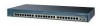
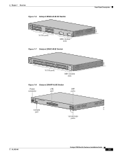
Front-Panel Description Figure 1-2 Catalyst 2950-24 Switch SYST RPS STAT UTIL DUPLX SPEED MODE 1 2 3 4x 5x 6x 7x 8x 9x 10x 11x 10Base-T / 100Base-TX 12x 13x 14x 15x 16x 17x 18x 19x 20x 21x 22x 23x Catalyst 2950 SERIES 24x 10/100 ports Figure 1-3 Catalyst 2950C-24 Switch SYST RPS STAT UTIL DUPLX ... RPS STAT UTIL DUPLX SPEED MODE 1 1X 23 45 67 8 9 10 11 12 11X 2X 12X 10/100 ports 1 Catalyst 2950 SERIES 2 GBIC module slots Figure 1-5 Catalyst 2950G-24-EI Switch SYST RPS STAT UTIL DUPLX SPEED MODE 1 1X 23 45 67 8 9 10 11 12 11X 2X 12X 13 13X ...
Front-Panel Description Figure 1-2 Catalyst 2950-24 Switch SYST RPS STAT UTIL DUPLX SPEED MODE 1 2 3 4x 5x 6x 7x 8x 9x 10x 11x 10Base-T / 100Base-TX 12x 13x 14x 15x 16x 17x 18x 19x 20x 21x 22x 23x Catalyst 2950 SERIES 24x 10/100 ports Figure 1-3 Catalyst 2950C-24 Switch SYST RPS STAT UTIL DUPLX ... RPS STAT UTIL DUPLX SPEED MODE 1 1X 23 45 67 8 9 10 11 12 11X 2X 12X 10/100 ports 1 Catalyst 2950 SERIES 2 GBIC module slots Figure 1-5 Catalyst 2950G-24-EI Switch SYST RPS STAT UTIL DUPLX SPEED MODE 1 1X 23 45 67 8 9 10 11 12 11X 2X 12X 13 13X ...
Hardware Installation Guide
Page 25
... 67 8 9 10 11 12 11X 2X 12X 13X 13 14 15 16 17 18 19 20 21 22 23 24 23X 14X 24X 10/100 ports 1 Catalyst 2950 SERIES 2 GBIC module slots Figure 1-7 Catalyst 2950G-48-EI Switch SYST RPS STAT UTIL DUPLX SPEED MODE 1 1X 2X 23 45 67 8 9 10 11 12 13 14 15... 21 22 23 24 25 26 27 28 29 30 31 32 16X 18X 33 31X 33X 34 35 36 37 38 39 40 41 42 43 44 45 46 47 48 47X 32X 34X 48X 10/100 ports Catalyst 2950 SERIES 1 2 GBIC module slots Figure 1-8 Catalyst 2950ST-8 LRE Switch Power LRE connector port SFP ports 110.00A...
... 67 8 9 10 11 12 11X 2X 12X 13X 13 14 15 16 17 18 19 20 21 22 23 24 23X 14X 24X 10/100 ports 1 Catalyst 2950 SERIES 2 GBIC module slots Figure 1-7 Catalyst 2950G-48-EI Switch SYST RPS STAT UTIL DUPLX SPEED MODE 1 1X 2X 23 45 67 8 9 10 11 12 13 14 15... 21 22 23 24 25 26 27 28 29 30 31 32 16X 18X 33 31X 33X 34 35 36 37 38 39 40 41 42 43 44 45 46 47 48 47X 32X 34X 48X 10/100 ports Catalyst 2950 SERIES 1 2 GBIC module slots Figure 1-8 Catalyst 2950ST-8 LRE Switch Power LRE connector port SFP ports 110.00A...
Hardware Installation Guide
Page 26
... ground lug 13 14 15 16 17 18 19 20 21 22 23 24 Catalyst 2950 SERIES LRE 997 1 2 1 2 DC ground lug 10/100/1000 ports Figure 1-11 Catalyst 2950SX-24 Switch SYST RPS STAT UTIL DUPLX SPEED MODE 1x 2x 3x 4x 5x 6x 7x 8x 9x 10x 11x 10BASE-T / 100BASE-TX 12x 13x 14x 15x ...
... ground lug 13 14 15 16 17 18 19 20 21 22 23 24 Catalyst 2950 SERIES LRE 997 1 2 1 2 DC ground lug 10/100/1000 ports Figure 1-11 Catalyst 2950SX-24 Switch SYST RPS STAT UTIL DUPLX SPEED MODE 1x 2x 3x 4x 5x 6x 7x 8x 9x 10x 11x 10BASE-T / 100BASE-TX 12x 13x 14x 15x ...
Hardware Installation Guide
Page 29
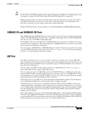
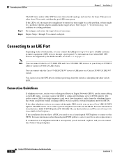
...the MT-RJ fiber-optic patch cables listed in Table 2-1 on the same Catalyst 2950ST-8 LRE or 2950ST-24 LRE switch. You can connect a 100BASE-FX or 1000BASE-SX port to an SC or ST port on a target device by using one of up to an attached device cannot... telephone networks and the PSTN. OL-6156-01 Catalyst 2950 Switch Hardware Installation Guide 1-9 Chapter 1 Overview Front-Panel Description Note On the Catalyst 2950 LRE switches, the four input uplink ports are connected through a PBX switch, a non-homologated POTS splitter, such as the Cisco LRE 48 POTS Splitter, can be connected to ...
...the MT-RJ fiber-optic patch cables listed in Table 2-1 on the same Catalyst 2950ST-8 LRE or 2950ST-24 LRE switch. You can connect a 100BASE-FX or 1000BASE-SX port to an SC or ST port on a target device by using one of up to an attached device cannot... telephone networks and the PSTN. OL-6156-01 Catalyst 2950 Switch Hardware Installation Guide 1-9 Chapter 1 Overview Front-Panel Description Note On the Catalyst 2950 LRE switches, the four input uplink ports are connected through a PBX switch, a non-homologated POTS splitter, such as the Cisco LRE 48 POTS Splitter, can be connected to ...

Hardware Installation Guide
Page 33
... meter [UTIL]) are visible through the GUI management applications-the Network Assistant application for multiple switches and the device manager for a single switch. Figure 1-15 LEDs on Catalyst 2950-12, 2950-24, 2950C-24, 2950SX-24, and 2950T-24 Switches RPS LED Port status LEDs System LED Port mode LEDs SYST RPS STAT UTIL DUPLX SPEED MODE Mode button 1x 2x 3x 4x...
... meter [UTIL]) are visible through the GUI management applications-the Network Assistant application for multiple switches and the device manager for a single switch. Figure 1-15 LEDs on Catalyst 2950-12, 2950-24, 2950C-24, 2950SX-24, and 2950T-24 Switches RPS LED Port status LEDs System LED Port mode LEDs SYST RPS STAT UTIL DUPLX SPEED MODE Mode button 1x 2x 3x 4x...

Hardware Installation Guide
Page 35
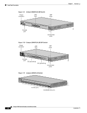
... STAT LED Speed Mode LED button 1 2 3 4 5 6 7 8 9 10 11 12 89364 OL-6156-01 Catalyst 2950 Switch Hardware Installation Guide 1-15 Chapter 1 Overview Front-Panel Description Figure 1-18 LEDs on Catalyst 2950ST-8 LRE and 2950ST-24 LRE Switches System LED Redundant power system LED Port status LEDs 81187 110.00A-1/02R.75A/TA2I0N500G--26400HVZ~ MODE SYST RPS STAT...
... STAT LED Speed Mode LED button 1 2 3 4 5 6 7 8 9 10 11 12 89364 OL-6156-01 Catalyst 2950 Switch Hardware Installation Guide 1-15 Chapter 1 Overview Front-Panel Description Figure 1-18 LEDs on Catalyst 2950ST-8 LRE and 2950ST-24 LRE Switches System LED Redundant power system LED Port status LEDs 81187 110.00A-1/02R.75A/TA2I0N500G--26400HVZ~ MODE SYST RPS STAT...
Hardware Installation Guide
Page 39
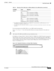
... operating at 10 Mbps Green Port is operating at 100 Mbps Flashing green Port is operating at 100 Mbps. For more of the total bandwidth. If all LEDs on a Catalyst 2950-12, 2950-24, 2950C-24, 2950SX-24, or 2950T-24 switch are green (no amber showing), the switch is using less than 50 percent of... the total bandwidth, and so on. Green Port is operating at 1000 Mbps 1. If the far-right LED is...
... operating at 10 Mbps Green Port is operating at 100 Mbps Flashing green Port is operating at 100 Mbps. For more of the total bandwidth. If all LEDs on a Catalyst 2950-12, 2950-24, 2950C-24, 2950SX-24, or 2950T-24 switch are green (no amber showing), the switch is using less than 50 percent of... the total bandwidth, and so on. Green Port is operating at 1000 Mbps 1. If the far-right LED is...

Hardware Installation Guide
Page 42
.... CONSOLE RPS connector Fan RJ-45 console port DC ground lug Figure 1-28 Catalyst 2950ST-8 LRE Switch, Catalyst 2950ST-24 LRE, and Catalyst 2950ST-24 LRE 997 Switch Rear Panel RPS Fans connector 81225 Power Connectors... You can order these L-shaped AC power cords from your Cisco sales representative: • CAB-NP1200-AC-AR= • CAB-NP1200-AC-AU= • CAB-NP1200-AC-CH= • CAB-NP1200-AC-EU= 1-22 Catalyst 2950 Switch...
.... CONSOLE RPS connector Fan RJ-45 console port DC ground lug Figure 1-28 Catalyst 2950ST-8 LRE Switch, Catalyst 2950ST-24 LRE, and Catalyst 2950ST-24 LRE 997 Switch Rear Panel RPS Fans connector 81225 Power Connectors... You can order these L-shaped AC power cords from your Cisco sales representative: • CAB-NP1200-AC-AR= • CAB-NP1200-AC-AU= • CAB-NP1200-AC-CH= • CAB-NP1200-AC-EU= 1-22 Catalyst 2950 Switch...
Hardware Installation Guide
Page 74
...2 Installation Step 1 When connecting to servers, workstations, and routers, insert a twisted-pair straight-through 4 to a Port on Catalyst 2950-12, 2950-24, 2950C-24, 2950SX-24, and 2950T-24 Switches SYST RPS STAT UTIL DUPLX SPEED MODE 1x 2x 3x 4x 5x 45576 Step 2 Step 3 Step 4 Step 5...to 1000BASE-T devices, be a problem with the adapter installed in the target device. Observe the port status LED. Figure 2-35 shows the Catalyst 2950-12, 2950-24, 2950C-24, 2950SX-24, and 2950T-24 switch as an example. If the LED is off, the target device might be sure to cabling ...
...2 Installation Step 1 When connecting to servers, workstations, and routers, insert a twisted-pair straight-through 4 to a Port on Catalyst 2950-12, 2950-24, 2950C-24, 2950SX-24, and 2950T-24 Switches SYST RPS STAT UTIL DUPLX SPEED MODE 1x 2x 3x 4x 5x 45576 Step 2 Step 3 Step 4 Step 5...to 1000BASE-T devices, be a problem with the adapter installed in the target device. Observe the port status LED. Figure 2-35 shows the Catalyst 2950-12, 2950-24, 2950C-24, 2950SX-24, and 2950T-24 switch as an example. If the LED is off, the target device might be sure to cabling ...
Hardware Installation Guide
Page 76
..., and you can connect the LRE port to up to 8 or up to 24 LRE customer premises equipment (CPE) devices through 5 to the patch panel. 2-30 Catalyst 2950 Switch Hardware Installation Guide OL-6156-01 If the other switch ports. Note You can use a homologated POTS splitter to connect to your Cisco sales representative. If the installation does...
..., and you can connect the LRE port to up to 8 or up to 24 LRE customer premises equipment (CPE) devices through 5 to the patch panel. 2-30 Catalyst 2950 Switch Hardware Installation Guide OL-6156-01 If the other switch ports. Note You can use a homologated POTS splitter to connect to your Cisco sales representative. If the installation does...
Hardware Installation Guide
Page 77
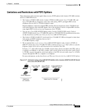
...Port Limitations and Restrictions with POTS Splitters These limitations and restrictions apply when you do not work when sharing a line with a Catalyst 2950ST-24 LRE 997 Switch and a Cisco 576 LRE 997 CPE PC Cisco 576 LRE Cisco LRE 48 Catalyst 2950ST-24 997 CPE POTS splitter LRE 997 switch...frequency range. • We recommend that you use a POTS splitter with Catalyst 2950 LRE switches and Cisco LRE CPE devices: • The Catalyst 2950ST-8 LRE switch, Catalyst 2950ST-24 LRE switch, Cisco 575 LRE CPE, and Cisco 585 LRE CPE are designed to share lines with analog and ISDN telephones ...
...Port Limitations and Restrictions with POTS Splitters These limitations and restrictions apply when you do not work when sharing a line with a Catalyst 2950ST-24 LRE 997 Switch and a Cisco 576 LRE 997 CPE PC Cisco 576 LRE Cisco LRE 48 Catalyst 2950ST-24 997 CPE POTS splitter LRE 997 switch...frequency range. • We recommend that you use a POTS splitter with Catalyst 2950 LRE switches and Cisco LRE CPE devices: • The Catalyst 2950ST-8 LRE switch, Catalyst 2950ST-24 LRE switch, Cisco 575 LRE CPE, and Cisco 585 LRE CPE are designed to share lines with analog and ISDN telephones ...

Hardware Installation Guide
Page 79
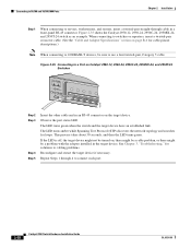
Chapter 2 Installation Connecting to an LRE Port Figure 2-38 Connecting to an LRE Port on a Catalyst 2950ST-8 LRE or 2950ST-24 LRE Switch RJ-21 connector 110.00A-1/02R.75A/TA2I0N500G--26400HVZ~ MODE SYST RPS STAT SPEED Screw CONSOLE 1 2 3 4 5 6 7 8 9 10 11 12 13 14 15 16 Screw Cable ... 11 12 RJ-21 connector 14 15 16 Screw RJ-21 connector Cable to wiring trunk 0.20 inch (5 mm) Cable tie 81569 OL-6156-01 Catalyst 2950 Switch Hardware Installation Guide 2-33
Chapter 2 Installation Connecting to an LRE Port Figure 2-38 Connecting to an LRE Port on a Catalyst 2950ST-8 LRE or 2950ST-24 LRE Switch RJ-21 connector 110.00A-1/02R.75A/TA2I0N500G--26400HVZ~ MODE SYST RPS STAT SPEED Screw CONSOLE 1 2 3 4 5 6 7 8 9 10 11 12 13 14 15 16 Screw Cable ... 11 12 RJ-21 connector 14 15 16 Screw RJ-21 connector Cable to wiring trunk 0.20 inch (5 mm) Cable tie 81569 OL-6156-01 Catalyst 2950 Switch Hardware Installation Guide 2-33

Hardware Installation Guide
Page 91
... Catalyst 2950G-24-EI-DC switch. RPS = redundant power system Catalyst 2950 Switch Hardware Installation Guide A-1 This switch meets ASTM D3332. 2. Table A-10 lists the regulatory agency approval only for the Catalyst 2950 LRE switches. Table A-1 Technical Specifications for Catalyst 2950-12, 2950-24, 2950C-24, 2950SX-24, and 2950T-24 Switches ...+12 V @4.5 A DC input voltages for the Cisco RPS 675 +12 V @4.5 A Power consumption 30 W (maximum) 102 Btus per sec)1 AC input voltage DC input voltages for fiber-optic uplink ports. per sec (2.13 m per hour Power rating Physical...
... Catalyst 2950G-24-EI-DC switch. RPS = redundant power system Catalyst 2950 Switch Hardware Installation Guide A-1 This switch meets ASTM D3332. 2. Table A-10 lists the regulatory agency approval only for the Catalyst 2950 LRE switches. Table A-1 Technical Specifications for Catalyst 2950-12, 2950-24, 2950C-24, 2950SX-24, and 2950T-24 Switches ...+12 V @4.5 A DC input voltages for the Cisco RPS 675 +12 V @4.5 A Power consumption 30 W (maximum) 102 Btus per sec)1 AC input voltage DC input voltages for fiber-optic uplink ports. per sec (2.13 m per hour Power rating Physical...
Hardware Installation Guide
Page 95
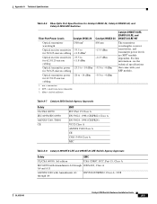
... module. Optical transmitter power -20 to -14 dBm for 50/125-micron cabling Catalyst 2950SX-24 850 nm -13.5 dBm -12.5 dBm -9.5 to -4 dBm 1. Appendix A Technical Specifications Table A-6 Fiber-Optic Port Specifications for Catalyst 2950C-24, Catalyst 2950SX-24, and Catalyst 2950 LRE Switches Fiber-Port Power Levels Catalyst 2950C-24 Optical transmitter wavelength 1300 nm1 Optical receiver sensitivity -33.5 to for 50/125-micron...
... module. Optical transmitter power -20 to -14 dBm for 50/125-micron cabling Catalyst 2950SX-24 850 nm -13.5 dBm -12.5 dBm -9.5 to -4 dBm 1. Appendix A Technical Specifications Table A-6 Fiber-Optic Port Specifications for Catalyst 2950C-24, Catalyst 2950SX-24, and Catalyst 2950 LRE Switches Fiber-Port Power Levels Catalyst 2950C-24 Optical transmitter wavelength 1300 nm1 Optical receiver sensitivity -33.5 to for 50/125-micron...

Hardware Installation Guide
Page 106
... Cable Schematic for 10/100/1000 and 1000BASE-T GBIC Module Ports Switch 1 TPO+ 2 TPO3 TP1+ 6 TP1- Table B-1 Catalyst 2950ST-24 LRE and Catalyst 2950ST-24 LRE 997 Switch RJ-21 Cable Pinouts Function Port 1 Tip Port 2 Tip Port 3 Tip Port 4 Tip Pin Pin Function 1 26 Port 1 Ring 2 27 Port 2 Ring 3 28 Port 3 Ring 4 29 Port 4 Ring Catalyst 2950 Switch Hardware Installation Guide B-8 OL-6156-01 Router or PC...
... Cable Schematic for 10/100/1000 and 1000BASE-T GBIC Module Ports Switch 1 TPO+ 2 TPO3 TP1+ 6 TP1- Table B-1 Catalyst 2950ST-24 LRE and Catalyst 2950ST-24 LRE 997 Switch RJ-21 Cable Pinouts Function Port 1 Tip Port 2 Tip Port 3 Tip Port 4 Tip Pin Pin Function 1 26 Port 1 Ring 2 27 Port 2 Ring 3 28 Port 3 Ring 4 29 Port 4 Ring Catalyst 2950 Switch Hardware Installation Guide B-8 OL-6156-01 Router or PC...

Hardware Installation Guide
Page 133
... technical specifications A-1 to A-7 Telnet, and accessing the CLI 2-24 temperature operating A-1 to A-4 terminal-emulation software D-4 troubleshooting diagnosing problems 4-1 to 4-3 understanding POST results 4-1 OL-6156-01 Index U uplink ports, LRE 2-9 URLs, Cisco xvii utilization bandwidth 2-17 to 2-21 LED 2-17 V verifying package contents 3-5 to 3-6 W warnings DC power C-1 to C-4 installation 3-1 to 3-4 Catalyst 2950 Switch Hardware Installation Guide IN-7
... technical specifications A-1 to A-7 Telnet, and accessing the CLI 2-24 temperature operating A-1 to A-4 terminal-emulation software D-4 troubleshooting diagnosing problems 4-1 to 4-3 understanding POST results 4-1 OL-6156-01 Index U uplink ports, LRE 2-9 URLs, Cisco xvii utilization bandwidth 2-17 to 2-21 LED 2-17 V verifying package contents 3-5 to 3-6 W warnings DC power C-1 to C-4 installation 3-1 to 3-4 Catalyst 2950 Switch Hardware Installation Guide IN-7


