Hardware Installation Guide
Page 4
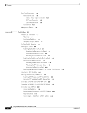
... Cisco RPS Connector 1-23 Console Port 1-24 Management Options 1-24 Installation 2-1 Preparing for Installation 2-1 Warnings 2-1 Installation Guidelines 2-4 Verifying Package Contents 2-5 Verifying Switch Operation 2-6 Installing the Switch 2-7 Installing the Switch in a Rack 2-7 Attaching the Brackets to the Switch 2-8 Mounting the Switch in...Switch on a Table, Shelf, or Desk 2-17 Installing the Switch on a Wall 2-17 Attaching the Brackets to the Switch 2-17 Attaching the RPS Connector Cover 2-18 Mounting the Switch to a Wall 2-18 Installing the Optional AC Ground Kit for Catalyst 2950 Switches...
... Cisco RPS Connector 1-23 Console Port 1-24 Management Options 1-24 Installation 2-1 Preparing for Installation 2-1 Warnings 2-1 Installation Guidelines 2-4 Verifying Package Contents 2-5 Verifying Switch Operation 2-6 Installing the Switch 2-7 Installing the Switch in a Rack 2-7 Attaching the Brackets to the Switch 2-8 Mounting the Switch in...Switch on a Table, Shelf, or Desk 2-17 Installing the Switch on a Wall 2-17 Attaching the Brackets to the Switch 2-17 Attaching the RPS Connector Cover 2-18 Mounting the Switch to a Wall 2-18 Installing the Optional AC Ground Kit for Catalyst 2950 Switches...
Hardware Installation Guide
Page 21
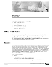
... from other switches. Some switch models can use switches with the CLI-Based Setup Program." Catalyst 2950-24 switch-24 10/100 Ethernet ports - Catalyst 2950C-24 switch-24 10/100 Ethernet ports and 2 100BASE-FX ports OL-6156-01 Catalyst 2950 Switch Hardware Installation Guide 1-1 and DC-powered switches, and troubleshooting help. Features The Catalyst 2950 switches are a family of the switch are cluster-capable, but only some models are stackable. Figure 1-1 through...
... from other switches. Some switch models can use switches with the CLI-Based Setup Program." Catalyst 2950-24 switch-24 10/100 Ethernet ports - Catalyst 2950C-24 switch-24 10/100 Ethernet ports and 2 100BASE-FX ports OL-6156-01 Catalyst 2950 Switch Hardware Installation Guide 1-1 and DC-powered switches, and troubleshooting help. Features The Catalyst 2950 switches are a family of the switch are cluster-capable, but only some models are stackable. Figure 1-1 through...

Hardware Installation Guide
Page 22
... • Configuration - Catalyst 2950SX-24 switch-24 10/100 Ethernet ports and 2 1000BASE-SX ports - Catalyst 2950ST-8 LRE switch-8 LRE ports, 2 10/100/1000 Ethernet ports, and 2 small-form-factor pluggable (SFP) module slots. (Two of supported SFP modules for the Catalyst 2950 LRE switches. - When the switch is running at 10 or 100 Mbps. On Catalyst 2950G-12-EI, 2950G-24-EI, 2950G-24-EI-DC, and...
... • Configuration - Catalyst 2950SX-24 switch-24 10/100 Ethernet ports and 2 1000BASE-SX ports - Catalyst 2950ST-8 LRE switch-8 LRE ports, 2 10/100/1000 Ethernet ports, and 2 small-form-factor pluggable (SFP) module slots. (Two of supported SFP modules for the Catalyst 2950 LRE switches. - When the switch is running at 10 or 100 Mbps. On Catalyst 2950G-12-EI, 2950G-24-EI, 2950G-24-EI-DC, and...

Hardware Installation Guide
Page 23
...and supplies DC output to the switch Certain Cisco LRE customer premises equipment (CPE) devices are not supported by certain Catalyst 2950 LRE switches. For more information on the console port on these switches, see the "Power Connectors" section on page 1-24. In Table 1-1, Yes means that... the CPE is supported by the switch. Connection for an optional Cisco RPS 300 redundant power system...
...and supplies DC output to the switch Certain Cisco LRE customer premises equipment (CPE) devices are not supported by certain Catalyst 2950 LRE switches. For more information on the console port on these switches, see the "Power Connectors" section on page 1-24. In Table 1-1, Yes means that... the CPE is supported by the switch. Connection for an optional Cisco RPS 300 redundant power system...

Hardware Installation Guide
Page 24
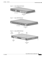
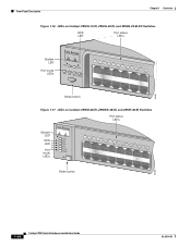
Front-Panel Description Figure 1-2 Catalyst 2950-24 Switch SYST RPS STAT UTIL DUPLX SPEED MODE 1 2 3 4x 5x 6x 7x 8x 9x 10x 11x 10Base-T / 100Base-TX 12x 13x 14x 15x 16x 17x 18x 19x 20x 21x 22x 23x Catalyst 2950 SERIES 24x 10/100 ports Figure 1-3 Catalyst 2950C-24 Switch SYST RPS STAT UTIL DUPLX ... RPS STAT UTIL DUPLX SPEED MODE 1 1X 23 45 67 8 9 10 11 12 11X 2X 12X 10/100 ports 1 Catalyst 2950 SERIES 2 GBIC module slots Figure 1-5 Catalyst 2950G-24-EI Switch SYST RPS STAT UTIL DUPLX SPEED MODE 1 1X 23 45 67 8 9 10 11 12 11X 2X 12X 13 13X ...
Front-Panel Description Figure 1-2 Catalyst 2950-24 Switch SYST RPS STAT UTIL DUPLX SPEED MODE 1 2 3 4x 5x 6x 7x 8x 9x 10x 11x 10Base-T / 100Base-TX 12x 13x 14x 15x 16x 17x 18x 19x 20x 21x 22x 23x Catalyst 2950 SERIES 24x 10/100 ports Figure 1-3 Catalyst 2950C-24 Switch SYST RPS STAT UTIL DUPLX ... RPS STAT UTIL DUPLX SPEED MODE 1 1X 23 45 67 8 9 10 11 12 11X 2X 12X 10/100 ports 1 Catalyst 2950 SERIES 2 GBIC module slots Figure 1-5 Catalyst 2950G-24-EI Switch SYST RPS STAT UTIL DUPLX SPEED MODE 1 1X 23 45 67 8 9 10 11 12 11X 2X 12X 13 13X ...
Hardware Installation Guide
Page 25
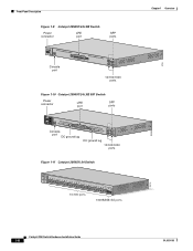
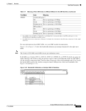
... 67 8 9 10 11 12 11X 2X 12X 13X 13 14 15 16 17 18 19 20 21 22 23 24 23X 14X 24X 10/100 ports 1 Catalyst 2950 SERIES 2 GBIC module slots Figure 1-7 Catalyst 2950G-48-EI Switch SYST RPS STAT UTIL DUPLX SPEED MODE 1 1X 2X 23 45 67 8 9 10 11 12 13 14 15... 21 22 23 24 25 26 27 28 29 30 31 32 16X 18X 33 31X 33X 34 35 36 37 38 39 40 41 42 43 44 45 46 47 48 47X 32X 34X 48X 10/100 ports Catalyst 2950 SERIES 1 2 GBIC module slots Figure 1-8 Catalyst 2950ST-8 LRE Switch Power LRE connector port SFP ports 110.00A...
... 67 8 9 10 11 12 11X 2X 12X 13X 13 14 15 16 17 18 19 20 21 22 23 24 23X 14X 24X 10/100 ports 1 Catalyst 2950 SERIES 2 GBIC module slots Figure 1-7 Catalyst 2950G-48-EI Switch SYST RPS STAT UTIL DUPLX SPEED MODE 1 1X 2X 23 45 67 8 9 10 11 12 13 14 15... 21 22 23 24 25 26 27 28 29 30 31 32 16X 18X 33 31X 33X 34 35 36 37 38 39 40 41 42 43 44 45 46 47 48 47X 32X 34X 48X 10/100 ports Catalyst 2950 SERIES 1 2 GBIC module slots Figure 1-8 Catalyst 2950ST-8 LRE Switch Power LRE connector port SFP ports 110.00A...
Hardware Installation Guide
Page 26
.../100/1000 ports Figure 1-10 Catalyst 2950ST-24 LRE 997 Switch Power connector LRE port SFP ports - ++ A INPCUUTR:RE3N6T- B 72 V :2-1 A - SYST RPS STAT SPEED MODE CONSOLE 1 2 3 4 5 6 7 8 9 10 11 12 Console port DC ground lug 13 14 15 16 17 18 19 20 21 22 23 24 Catalyst 2950 SERIES LRE 997 1 2 1 2 DC ground lug 10/100/1000 ports Figure 1-11 Catalyst 2950SX-24 Switch SYST...
.../100/1000 ports Figure 1-10 Catalyst 2950ST-24 LRE 997 Switch Power connector LRE port SFP ports - ++ A INPCUUTR:RE3N6T- B 72 V :2-1 A - SYST RPS STAT SPEED MODE CONSOLE 1 2 3 4 5 6 7 8 9 10 11 12 Console port DC ground lug 13 14 15 16 17 18 19 20 21 22 23 24 Catalyst 2950 SERIES LRE 997 1 2 1 2 DC ground lug 10/100/1000 ports Figure 1-11 Catalyst 2950SX-24 Switch SYST...
Hardware Installation Guide
Page 27
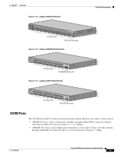
...Catalyst 2950T-24 Switch Front-Panel Description 47337 SYST RPS STAT UTIL DUPLX SPEED MODE 1x 2x 3x 4x 5x 6x 7x 8x 9x 10x 11x 10Base-T / 100Base-TX 12x 13x 14x 15x 16x 17x 18x 19x 20x 21x 22x 23x Catalyst 2950 SERIES 24x 10/100/100Base-T 1 2 10/100 ports 10/100/1000 ports Figure 1-13 Catalyst 2950SX...-48-SI Switch 97630 SYST RPS STAT UTIL DUPLX SPEED MODE 1 1X 2X 23 45 67 8...
...Catalyst 2950T-24 Switch Front-Panel Description 47337 SYST RPS STAT UTIL DUPLX SPEED MODE 1x 2x 3x 4x 5x 6x 7x 8x 9x 10x 11x 10Base-T / 100Base-TX 12x 13x 14x 15x 16x 17x 18x 19x 20x 21x 22x 23x Catalyst 2950 SERIES 24x 10/100/100Base-T 1 2 10/100 ports 10/100/1000 ports Figure 1-13 Catalyst 2950SX...-48-SI Switch 97630 SYST RPS STAT UTIL DUPLX SPEED MODE 1 1X 2X 23 45 67 8...
Hardware Installation Guide
Page 28
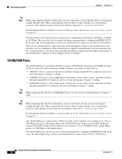
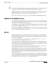
... Mbps, or 100 Mbps. In all cases, the cable length from a switch to an attached device cannot exceed 328 feet (100 meters). The 10/100/1000 ports on the Catalyst 2950T-48-SI and Catalyst 2950 LRE switches can also be set to operate at 10 or 100 Mbps in full-duplex..., if the attached device supports it) and configures itself accordingly. 10/100/1000 Ports The 10/100/1000 ports on Catalyst 2950T-24, Catalyst 2950T-48-SI, and Catalyst 2950 LRE switches use RJ-45 connectors and twisted-pair cabling. The 10/100/1000 ports on the Catalyst 2950T-24 switch can connect to hubs or other...
... Mbps, or 100 Mbps. In all cases, the cable length from a switch to an attached device cannot exceed 328 feet (100 meters). The 10/100/1000 ports on the Catalyst 2950T-48-SI and Catalyst 2950 LRE switches can also be set to operate at 10 or 100 Mbps in full-duplex..., if the attached device supports it) and configures itself accordingly. 10/100/1000 Ports The 10/100/1000 ports on Catalyst 2950T-24, Catalyst 2950T-48-SI, and Catalyst 2950 LRE switches use RJ-45 connectors and twisted-pair cabling. The 10/100/1000 ports on the Catalyst 2950T-24 switch can connect to hubs or other...
Hardware Installation Guide
Page 29
...Catalyst 2950 LRE switch senses more information about configuring the LRE ports, see the Installation and Warranty Notes for both use 50/125- The 100BASE-FX ports operate only at 100 Mbps in full-duplex mode, and the 1000BASE-SX ports operate only at one RJ-21 connector to connect up to 24 Cisco...feet (1500 meters). Chapter 1 Overview Front-Panel Description Note On the Catalyst 2950 LRE switches, the four input uplink ports are connected through a PBX switch, a non-homologated POTS splitter, such as the Cisco LRE 48 POTS Splitter, can be connected to the patch panel through ...
...Catalyst 2950 LRE switch senses more information about configuring the LRE ports, see the Installation and Warranty Notes for both use 50/125- The 100BASE-FX ports operate only at 100 Mbps in full-duplex mode, and the 1000BASE-SX ports operate only at one RJ-21 connector to connect up to 24 Cisco...feet (1500 meters). Chapter 1 Overview Front-Panel Description Note On the Catalyst 2950 LRE switches, the four input uplink ports are connected through a PBX switch, a non-homologated POTS splitter, such as the Cisco LRE 48 POTS Splitter, can be connected to the patch panel through ...

Hardware Installation Guide
Page 33
... GUI management applications-the Network Assistant application for multiple switches and the device manager for a single switch. The switch software configuration guide describes how to use to monitor switch activity and performance. Figure 1-15 LEDs on Catalyst 2950-12, 2950-24, 2950C-24, 2950SX-24, and 2950T-24 Switches RPS LED Port status LEDs System LED Port mode LEDs SYST RPS STAT UTIL DUPLX SPEED...
... GUI management applications-the Network Assistant application for multiple switches and the device manager for a single switch. The switch software configuration guide describes how to use to monitor switch activity and performance. Figure 1-15 LEDs on Catalyst 2950-12, 2950-24, 2950C-24, 2950SX-24, and 2950T-24 Switches RPS LED Port status LEDs System LED Port mode LEDs SYST RPS STAT UTIL DUPLX SPEED...
Hardware Installation Guide
Page 34
...Catalyst 2950G-12-EI, 2950G-24-EI, and 2950G-24-EI-DC Switches RPS LED Port status LEDs 65395 System LED Port mode LEDs SYST RPS STAT UTIL DUPLX SPEED MODE 1 1X 23 45 67 8 9 10 11 12 11X 2X 12X Mode button Figure 1-17 LEDs on Catalyst 2950G-48-EI, 2950SX-48-SI, and 2950T-48-SI Switches Port... status LEDs System LED RPS LED Port mode LEDs SYST RPS STAT UTIL DUPLX SPEED MODE 1 1X 23 45 67 89 10 11 12 13 14 15 16 15X 2X 16X Mode button 65508 1-14 Catalyst 2950 Switch Hardware Installation Guide...
...Catalyst 2950G-12-EI, 2950G-24-EI, and 2950G-24-EI-DC Switches RPS LED Port status LEDs 65395 System LED Port mode LEDs SYST RPS STAT UTIL DUPLX SPEED MODE 1 1X 23 45 67 8 9 10 11 12 11X 2X 12X Mode button Figure 1-17 LEDs on Catalyst 2950G-48-EI, 2950SX-48-SI, and 2950T-48-SI Switches Port... status LEDs System LED RPS LED Port mode LEDs SYST RPS STAT UTIL DUPLX SPEED MODE 1 1X 23 45 67 89 10 11 12 13 14 15 16 15X 2X 16X Mode button 65508 1-14 Catalyst 2950 Switch Hardware Installation Guide...

Hardware Installation Guide
Page 35
... STAT LED Speed Mode LED button 1 2 3 4 5 6 7 8 9 10 11 12 89364 OL-6156-01 Catalyst 2950 Switch Hardware Installation Guide 1-15 Chapter 1 Overview Front-Panel Description Figure 1-18 LEDs on Catalyst 2950ST-8 LRE and 2950ST-24 LRE Switches System LED Redundant power system LED Port status LEDs 81187 110.00A-1/02R.75A/TA2I0N500G--26400HVZ~ MODE SYST RPS STAT...
... STAT LED Speed Mode LED button 1 2 3 4 5 6 7 8 9 10 11 12 89364 OL-6156-01 Catalyst 2950 Switch Hardware Installation Guide 1-15 Chapter 1 Overview Front-Panel Description Figure 1-18 LEDs on Catalyst 2950ST-8 LRE and 2950ST-24 LRE Switches System LED Redundant power system LED Port status LEDs 81187 110.00A-1/02R.75A/TA2I0N500G--26400HVZ~ MODE SYST RPS STAT...

Hardware Installation Guide
Page 37
... See Figure 1-20 to interpret the colors for details. Flashing green Activity. Port was powered on a logarithmic scale. Table 1-7 explains how to Figure 1-24 for the LRE switches. UTIL (utilization) Green The current backplane utilization that is operating in full duplex. A Catalyst 2950 LRE switch does not have a UTIL or a DUPLX LED. Table 1-6 Meaning of the...
... See Figure 1-20 to interpret the colors for details. Flashing green Activity. Port was powered on a logarithmic scale. Table 1-7 explains how to Figure 1-24 for the LRE switches. UTIL (utilization) Green The current backplane utilization that is operating in full duplex. A Catalyst 2950 LRE switch does not have a UTIL or a DUPLX LED. Table 1-6 Meaning of the...
Hardware Installation Guide
Page 39
...-Panel Description Table 1-7 Meaning of Port LED Colors in Different Modes for Uplink Port 1 and Uplink Port 2 correspond either to the SFP module port or to the 10/100/1000 port, depending on a Catalyst 2950-12, 2950-24, 2950C-24, 2950SX-24, or 2950T-24 switch are green (no amber showing), the switch is active. 2. Figure 1-20 to Figure 1-24 show the bandwidth utilization percentages displayed...
...-Panel Description Table 1-7 Meaning of Port LED Colors in Different Modes for Uplink Port 1 and Uplink Port 2 correspond either to the SFP module port or to the 10/100/1000 port, depending on a Catalyst 2950-12, 2950-24, 2950C-24, 2950SX-24, or 2950T-24 switch are green (no amber showing), the switch is active. 2. Figure 1-20 to Figure 1-24 show the bandwidth utilization percentages displayed...

Hardware Installation Guide
Page 41
...-45 console port Figure 1-26 Catalyst 2950G-48-EI, Catalyst 2950SX-48-SI, and Catalyst 2950T-48-SI Switch Rear Panel 65511 12005R@[email protected]~~ AC power connector [email protected]. Chapter 1 Overview Rear-Panel Description Figure 1-24 Bandwidth Utilization on Catalyst 2950G-48-EI, 2950SX-48-SI, and 2950T-48-SI Switches 65510 Catalyst 2950 12 1X 3 24 56 78...
...-45 console port Figure 1-26 Catalyst 2950G-48-EI, Catalyst 2950SX-48-SI, and Catalyst 2950T-48-SI Switch Rear Panel 65511 12005R@[email protected]~~ AC power connector [email protected]. Chapter 1 Overview Rear-Panel Description Figure 1-24 Bandwidth Utilization on Catalyst 2950G-48-EI, 2950SX-48-SI, and 2950T-48-SI Switches 65510 Catalyst 2950 12 1X 3 24 56 78...

Hardware Installation Guide
Page 42
...outlet. CONSOLE RPS connector Fan RJ-45 console port DC ground lug Figure 1-28 Catalyst 2950ST-8 LRE Switch, Catalyst 2950ST-24 LRE, and Catalyst 2950ST-24 LRE 997 Switch Rear Panel RPS Fans connector 81225 Power Connectors ...You can order these L-shaped AC power cords from your Cisco sales representative: • CAB-NP1200-AC-AR= • CAB-NP1200-AC-AU= • CAB-NP1200-AC-CH= • CAB-NP1200-AC-EU= 1-22 Catalyst 2950 Switch...
...outlet. CONSOLE RPS connector Fan RJ-45 console port DC ground lug Figure 1-28 Catalyst 2950ST-8 LRE Switch, Catalyst 2950ST-24 LRE, and Catalyst 2950ST-24 LRE 997 Switch Rear Panel RPS Fans connector 81225 Power Connectors ...You can order these L-shaped AC power cords from your Cisco sales representative: • CAB-NP1200-AC-AR= • CAB-NP1200-AC-AU= • CAB-NP1200-AC-CH= • CAB-NP1200-AC-EU= 1-22 Catalyst 2950 Switch...
Hardware Installation Guide
Page 44
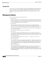
... SNMP application. 1-24 Catalyst 2950 Switch Hardware Installation Guide OL-6156-01 This application, which is attached to your network, you can install and run it. You can use the device manager, which you do not need to provide an RJ-45-to the console port on page B-6. For more information. • Cisco IOS CLI. Use...
... SNMP application. 1-24 Catalyst 2950 Switch Hardware Installation Guide OL-6156-01 This application, which is attached to your network, you can install and run it. You can use the device manager, which you do not need to provide an RJ-45-to the console port on page B-6. For more information. • Cisco IOS CLI. Use...
Hardware Installation Guide
Page 74
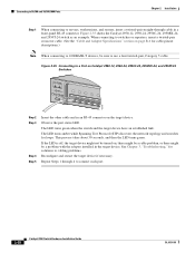
... Tree Protocol (STP) discovers the network topology and searches for solutions to servers, workstations, and routers, insert a twisted-pair straight-through 4 to a Port on Catalyst 2950-12, 2950-24, 2950C-24, 2950SX-24, and 2950T-24 Switches SYST RPS STAT UTIL DUPLX SPEED MODE 1x 2x 3x 4x 5x 45576 Step 2 Step 3 Step 4 Step 5 Insert the other cable end in...
... Tree Protocol (STP) discovers the network topology and searches for solutions to servers, workstations, and routers, insert a twisted-pair straight-through 4 to a Port on Catalyst 2950-12, 2950-24, 2950C-24, 2950SX-24, and 2950T-24 Switches SYST RPS STAT UTIL DUPLX SPEED MODE 1x 2x 3x 4x 5x 45576 Step 2 Step 3 Step 4 Step 5 Insert the other cable end in...

Hardware Installation Guide
Page 91
...Catalyst 2950G-24-EI-DC switch. RPS = redundant power system Catalyst 2950 Switch Hardware Installation Guide A-1 Table A-10 lists the regulatory agency approval only for the switches other than the Catalyst 2950 Long-Reach Ethernet (LRE) switches. This switch meets ASTM D3332. 2. Table A-6 lists the technical specifications for Catalyst 2950-12, 2950-24, 2950C-24, 2950SX-24, and 2950T-24 Switches...Hz +12 V @4.5 A DC input voltages for the Catalyst 2950 LRE switches. Table A-1 Technical Specifications for fiber-optic uplink ports. A A P P E N D I X Technical Specifications OL-...
...Catalyst 2950G-24-EI-DC switch. RPS = redundant power system Catalyst 2950 Switch Hardware Installation Guide A-1 Table A-10 lists the regulatory agency approval only for the switches other than the Catalyst 2950 Long-Reach Ethernet (LRE) switches. This switch meets ASTM D3332. 2. Table A-6 lists the technical specifications for Catalyst 2950-12, 2950-24, 2950C-24, 2950SX-24, and 2950T-24 Switches...Hz +12 V @4.5 A DC input voltages for the Catalyst 2950 LRE switches. Table A-1 Technical Specifications for fiber-optic uplink ports. A A P P E N D I X Technical Specifications OL-...


