Hardware Installation Guide
Page 44
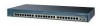
...connection to manage and monitor switch clusters or standalone devices. Use the device manager to the console port on the switch. You can access the device manager from Cisco. You can order a ...24 Catalyst 2950 Switch Hardware Installation Guide OL-6156-01 This application, which is a GUI-based application that adapter from anywhere in the web browser, and press Enter. The switch supports a comprehensive set configuration parameters and to run on page B-6. For more information, see the "Cable and Adapter Specifications" section on your network through the console port...
...connection to manage and monitor switch clusters or standalone devices. Use the device manager to the console port on the switch. You can access the device manager from Cisco. You can order a ...24 Catalyst 2950 Switch Hardware Installation Guide OL-6156-01 This application, which is a GUI-based application that adapter from anywhere in the web browser, and press Enter. The switch supports a comprehensive set configuration parameters and to run on page B-6. For more information, see the "Cable and Adapter Specifications" section on your network through the console port...

Hardware Installation Guide
Page 51
... Specifications." • Clearance to ports is within reach of a circuit breaker. - See the "LRE Port" section on a table, shelf, or desk - Access to front and rear panels meet these items: - The switch is missing or damaged, contact your Cisco representative or reseller for damage. Two 19-inch or 24-inch rack-mounting brackets OL-6156-01 Catalyst 2950 Switch...
... Specifications." • Clearance to ports is within reach of a circuit breaker. - See the "LRE Port" section on a table, shelf, or desk - Access to front and rear panels meet these items: - The switch is missing or damaged, contact your Cisco representative or reseller for damage. Two 19-inch or 24-inch rack-mounting brackets OL-6156-01 Catalyst 2950 Switch...
Hardware Installation Guide
Page 74
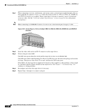
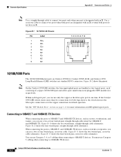
...See the "Cable and Adapter Specifications" section on page B-6 for cable-pinout descriptions.) Note When connecting to 1000BASE-T devices, be a problem with the adapter installed in an RJ-45 connector on Catalyst 2950-12, 2950-24, 2950C-24, 2950SX-24, and 2950T-24 Switches SYST RPS STAT UTIL DUPLX ...to a Port on the target device. Observe the port status LED. Connecting to 10/100 and 10/100/1000 Ports Chapter 2 Installation Step 1 When connecting to servers, workstations, and routers, insert a twisted-pair straight-through 4 to connect each port. 2-28 Catalyst 2950 Switch Hardware ...
...See the "Cable and Adapter Specifications" section on page B-6 for cable-pinout descriptions.) Note When connecting to 1000BASE-T devices, be a problem with the adapter installed in an RJ-45 connector on Catalyst 2950-12, 2950-24, 2950C-24, 2950SX-24, and 2950T-24 Switches SYST RPS STAT UTIL DUPLX ...to a Port on the target device. Observe the port status LED. Connecting to 10/100 and 10/100/1000 Ports Chapter 2 Installation Step 1 When connecting to servers, workstations, and routers, insert a twisted-pair straight-through 4 to connect each port. 2-28 Catalyst 2950 Switch Hardware ...
Hardware Installation Guide
Page 77
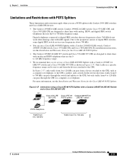
... to 120 kHz can be sent to and from a device attached to the CPE, such as shown in a specific frequency range can pass from the devices attached to the CPE. For more information, see the Installation and Warranty Notes for the..., and a switch. Chapter 2 Installation Connecting to an LRE Port Limitations and Restrictions with POTS Splitters These limitations and restrictions apply when you use a POTS splitter with Catalyst 2950 LRE switches and Cisco LRE CPE devices: • The Catalyst 2950ST-8 LRE switch, Catalyst 2950ST-24 LRE switch, Cisco 575 LRE CPE, and Cisco 585 LRE CPE...
... to 120 kHz can be sent to and from a device attached to the CPE, such as shown in a specific frequency range can pass from the devices attached to the CPE. For more information, see the Installation and Warranty Notes for the..., and a switch. Chapter 2 Installation Connecting to an LRE Port Limitations and Restrictions with POTS Splitters These limitations and restrictions apply when you use a POTS splitter with Catalyst 2950 LRE switches and Cisco LRE CPE devices: • The Catalyst 2950ST-8 LRE switch, Catalyst 2950ST-24 LRE switch, Cisco 575 LRE CPE, and Cisco 585 LRE CPE...

Hardware Installation Guide
Page 91
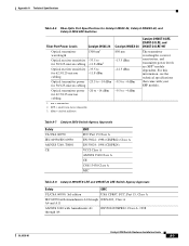
...-6156-01 Table A-1 through Table A-5 list the technical specifications for the Cisco RPS 675 +12 V @4.5 A Power consumption 30 W (maximum) 102 Btus per hour Power rating Physical Dimensions 0.05 kVA Weight 6.5 lb (3 kg) Dimensions (H x W x D) 1.72 x 17.5 x 9.52 in . Table A-1 Technical Specifications for Catalyst 2950-12, 2950-24, 2950C-24, 2950SX-24, and 2950T-24 Switches Environmental Ranges Operating temperature 32 to 113°...
...-6156-01 Table A-1 through Table A-5 list the technical specifications for the Cisco RPS 675 +12 V @4.5 A Power consumption 30 W (maximum) 102 Btus per hour Power rating Physical Dimensions 0.05 kVA Weight 6.5 lb (3 kg) Dimensions (H x W x D) 1.72 x 17.5 x 9.52 in . Table A-1 Technical Specifications for Catalyst 2950-12, 2950-24, 2950C-24, 2950SX-24, and 2950T-24 Switches Environmental Ranges Operating temperature 32 to 113°...
Hardware Installation Guide
Page 95
... SFP module. Optical transmitter power -20 to -14 dBm for 50/125-micron cabling Catalyst 2950SX-24 850 nm -13.5 dBm -12.5 dBm -9.5 to -4 dBm 1. Appendix A Technical Specifications Table A-6 Fiber-Optic Port Specifications for Catalyst 2950C-24, Catalyst 2950SX-24, and Catalyst 2950 LRE Switches Fiber-Port Power Levels Catalyst 2950C-24 Optical transmitter wavelength 1300 nm1 Optical receiver sensitivity -33.5 to for 50/125-micron cabling...
... SFP module. Optical transmitter power -20 to -14 dBm for 50/125-micron cabling Catalyst 2950SX-24 850 nm -13.5 dBm -12.5 dBm -9.5 to -4 dBm 1. Appendix A Technical Specifications Table A-6 Fiber-Optic Port Specifications for Catalyst 2950C-24, Catalyst 2950SX-24, and Catalyst 2950 LRE Switches Fiber-Port Power Levels Catalyst 2950C-24 Optical transmitter wavelength 1300 nm1 Optical receiver sensitivity -33.5 to for 50/125-micron cabling...
Hardware Installation Guide
Page 100
... twisted-pair, crossover cable schematics. Connector Specifications Appendix B Connectors and Cables Note Use a straight-through cable to connect two ports only when one time. Note On the Catalyst 2950 LRE switches, the four input uplink ports are designated with an X. When connecting the ports to connect two ports when both logical ports, the switch chooses the fiber-optic connections over...
... twisted-pair, crossover cable schematics. Connector Specifications Appendix B Connectors and Cables Note Use a straight-through cable to connect two ports only when one time. Note On the Catalyst 2950 LRE switches, the four input uplink ports are designated with an X. When connecting the ports to connect two ports when both logical ports, the switch chooses the fiber-optic connections over...

Hardware Installation Guide
Page 101
... 26 Catalyst 2950 Switch Hardware Installation Guide B-3 Figure B-15 shows the crossover cable schematics. Figure B-2 RJ-45 Pinouts for 10BASE-T, 100BASE-TX, and 1000BASE-T. Each LRE port uses two pins. Figure B-14 shows the straight-through cable to connect two ports when both ports do not have an X. Because the Catalyst 2950ST-24 LRE and Catalyst 2950ST-24 LRE 997 switches...
... 26 Catalyst 2950 Switch Hardware Installation Guide B-3 Figure B-15 shows the crossover cable schematics. Figure B-2 RJ-45 Pinouts for 10BASE-T, 100BASE-TX, and 1000BASE-T. Each LRE port uses two pins. Figure B-14 shows the straight-through cable to connect two ports when both ports do not have an X. Because the Catalyst 2950ST-24 LRE and Catalyst 2950ST-24 LRE 997 switches...

Hardware Installation Guide
Page 106
... 10/100/1000 and 1000BASE-T GBIC Module Ports Switch 1 TPO+ 2 TPO3 TP1+ 6 TP1- Table B-1 Catalyst 2950ST-24 LRE and Catalyst 2950ST-24 LRE 997 Switch RJ-21 Cable Pinouts Function Port 1 Tip Port 2 Tip Port 3 Tip Port 4 Tip Pin Pin Function 1 26 Port 1 Ring 2 27 Port 2 Ring 3 28 Port 3 Ring 4 29 Port 4 Ring Catalyst 2950 Switch Hardware Installation Guide B-8 OL-6156-01 Switch 1 TP0+ 2 TP03 TP1+ 6 TP1- 4 TP2+ 5 TP27...
... 10/100/1000 and 1000BASE-T GBIC Module Ports Switch 1 TPO+ 2 TPO3 TP1+ 6 TP1- Table B-1 Catalyst 2950ST-24 LRE and Catalyst 2950ST-24 LRE 997 Switch RJ-21 Cable Pinouts Function Port 1 Tip Port 2 Tip Port 3 Tip Port 4 Tip Pin Pin Function 1 26 Port 1 Ring 2 27 Port 2 Ring 3 28 Port 3 Ring 4 29 Port 4 Ring Catalyst 2950 Switch Hardware Installation Guide B-8 OL-6156-01 Switch 1 TP0+ 2 TP03 TP1+ 6 TP1- 4 TP2+ 5 TP27...

Hardware Installation Guide
Page 107
...-6156-01 Catalyst 2950 Switch Hardware Installation Guide B-9 Appendix B Connectors and Cables Cable and Adapter Specifications Table B-1 Catalyst 2950ST-24 LRE and Catalyst 2950ST-24 LRE 997 Switch RJ-21 Cable Pinouts Function Pin Pin Function Port 5 Tip 5 30 Port 5 Ring Port 6 Tip 6 31 Port 6 Ring Port 7 Tip 7 32 Port 7 Ring Port 8 Tip 8 33 Port 8 Ring Port 9 Tip 9 34 Port 9 Ring Port 10 Tip 10 35 Port 10 Ring Port 11 Tip...
...-6156-01 Catalyst 2950 Switch Hardware Installation Guide B-9 Appendix B Connectors and Cables Cable and Adapter Specifications Table B-1 Catalyst 2950ST-24 LRE and Catalyst 2950ST-24 LRE 997 Switch RJ-21 Cable Pinouts Function Pin Pin Function Port 5 Tip 5 30 Port 5 Ring Port 6 Tip 6 31 Port 6 Ring Port 7 Tip 7 32 Port 7 Ring Port 8 Tip 8 33 Port 8 Ring Port 9 Tip 9 34 Port 9 Ring Port 10 Tip 10 35 Port 10 Ring Port 11 Tip...

Hardware Installation Guide
Page 108
...Cabling Console Port (DTE) RJ-45-to -DB-9 adapter cable, and the console device. Cable and Adapter Specifications Appendix B Connectors and Cables Table B-2 Catalyst 2950ST-8 LRE Switch RJ-21...48 No connect No connect 24 49 No connect No connect 25 50 No connect Adapter Pinouts Table B-3 lists the pinouts for the console port, the RJ-45-to... -DB-9 Adapter Cable Signal RJ-45 Pin DB-9 Pin RTS 1 8 Not connected 2 6 TxD 3 2 GND 4 5 GND 5 5 RxD 6 3 Not connected 7 4 CTS 8 7 Console Device Signal CTS DSR RxD GND GND TxD DTR RTS B-10 Catalyst 2950 Switch...
...Cabling Console Port (DTE) RJ-45-to -DB-9 adapter cable, and the console device. Cable and Adapter Specifications Appendix B Connectors and Cables Table B-2 Catalyst 2950ST-8 LRE Switch RJ-21...48 No connect No connect 24 49 No connect No connect 25 50 No connect Adapter Pinouts Table B-3 lists the pinouts for the console port, the RJ-45-to... -DB-9 Adapter Cable Signal RJ-45 Pin DB-9 Pin RTS 1 8 Not connected 2 6 TxD 3 2 GND 4 5 GND 5 5 RxD 6 3 Not connected 7 4 CTS 8 7 Console Device Signal CTS DSR RxD GND GND TxD DTR RTS B-10 Catalyst 2950 Switch...
Hardware Installation Guide
Page 129
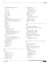
...connector 2-23 specifications A-2, A-4 warnings C-1 to C-4 desk-mounting 3-17 OL-6156-01 Index Device Manager xvi description 2-24 to configure switch 3-40 viewing LEDs 2-13 dimensions A-1 to A-4 documentation ordering xvii related publications xv to xvi URLs, Cisco xvii document... using D-1 F fan problems, solving 4-3 features 2-1 to 2-3 feedback to Cisco Systems, web xviii fiber-optic port specifications A-5 front panel 10/100/1000 ports 2-8 10/100 ports 2-7 to 2-8 1000BASE-SX ports 2-9 100BASE-FX ports 2-9 clearance 3-5 described 2-3 Catalyst 2950 Switch Hardware Installation Guide IN-3
...connector 2-23 specifications A-2, A-4 warnings C-1 to C-4 desk-mounting 3-17 OL-6156-01 Index Device Manager xvi description 2-24 to configure switch 3-40 viewing LEDs 2-13 dimensions A-1 to A-4 documentation ordering xvii related publications xv to xvi URLs, Cisco xvii document... using D-1 F fan problems, solving 4-3 features 2-1 to 2-3 feedback to Cisco Systems, web xviii fiber-optic port specifications A-5 front panel 10/100/1000 ports 2-8 10/100 ports 2-7 to 2-8 1000BASE-SX ports 2-9 100BASE-FX ports 2-9 clearance 3-5 described 2-3 Catalyst 2950 Switch Hardware Installation Guide IN-3

Hardware Installation Guide
Page 133
... to xix technical specifications A-1 to A-7 Telnet, and accessing the CLI 2-24 temperature operating A-1 to A-4 terminal-emulation software D-4 troubleshooting diagnosing problems 4-1 to 4-3 understanding POST results 4-1 OL-6156-01 Index U uplink ports, LRE 2-9 URLs, Cisco xvii utilization bandwidth 2-17 to 2-21 LED 2-17 V verifying package contents 3-5 to 3-6 W warnings DC power C-1 to C-4 installation 3-1 to 3-4 Catalyst 2950 Switch Hardware Installation Guide...
... to xix technical specifications A-1 to A-7 Telnet, and accessing the CLI 2-24 temperature operating A-1 to A-4 terminal-emulation software D-4 troubleshooting diagnosing problems 4-1 to 4-3 understanding POST results 4-1 OL-6156-01 Index U uplink ports, LRE 2-9 URLs, Cisco xvii utilization bandwidth 2-17 to 2-21 LED 2-17 V verifying package contents 3-5 to 3-6 W warnings DC power C-1 to C-4 installation 3-1 to 3-4 Catalyst 2950 Switch Hardware Installation Guide...


