Hardware Installation Guide
Page 83
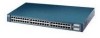
...Step 1 Connect one end of a wiring trunk cable to the RJ-21 connector of digital PBX switches, some digital PBX switch services use frequencies above . Note Cisco LRE products are ...switches that use the 0 to 700 kHz frequency range. To connect the LRE port to a patch panel or POTS splitter, follow these cables from your Cisco sales representative for more information. Contact your Cisco sales.... [CSCdu73260] Note If no other telephone services travel on the switch. (See Figure 2-30.) 78-6461-04 Catalyst 2900 Series XL Hardware Installation Guide 2-39 Chapter 2 Installation Connecting ...
...Step 1 Connect one end of a wiring trunk cable to the RJ-21 connector of digital PBX switches, some digital PBX switch services use frequencies above . Note Cisco LRE products are ...switches that use the 0 to 700 kHz frequency range. To connect the LRE port to a patch panel or POTS splitter, follow these cables from your Cisco sales representative for more information. Contact your Cisco sales.... [CSCdu73260] Note If no other telephone services travel on the switch. (See Figure 2-30.) 78-6461-04 Catalyst 2900 Series XL Hardware Installation Guide 2-39 Chapter 2 Installation Connecting ...
Hardware Installation Guide
Page 85
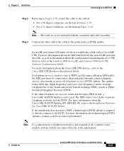
... your Cisco sales representative. Each LRE port status LED turns on when it establishes a link with the connector and cable assembly. The PBX routes voice traffic to the switch and private branch exchange (PBX) switch or Public Switched Telephone Network (PSTN). For more information about the Cisco LRE 48 POTS Splitter (PS-1M-LRE-48), refer to the Catalyst...
... your Cisco sales representative. Each LRE port status LED turns on when it establishes a link with the connector and cable assembly. The PBX routes voice traffic to the switch and private branch exchange (PBX) switch or Public Switched Telephone Network (PSTN). For more information about the Cisco LRE 48 POTS Splitter (PS-1M-LRE-48), refer to the Catalyst...