Configuration Guide
Page 33
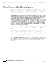
...switches directly to nine Catalyst 2900 XL, Catalyst 2950, Catalyst 3500 XL, and Catalyst 3550 switches through GigaStack GBIC connections. Using Gigabit modules on two of the switches, you can have redundant uplink connections to 432 users. Using the following Gigabit modules also provides flexibility in a star configuration. Using the required Cisco...per port to prioritize voice and data traffic as either high- To preserve switch connectivity... of Catalyst 2950-48 switches, you can connect up to a Gigabit backbone switch such as the Catalyst 3550-12G switch. Chapter...
...switches directly to nine Catalyst 2900 XL, Catalyst 2950, Catalyst 3500 XL, and Catalyst 3550 switches through GigaStack GBIC connections. Using Gigabit modules on two of the switches, you can have redundant uplink connections to 432 users. Using the following Gigabit modules also provides flexibility in a star configuration. Using the required Cisco...per port to prioritize voice and data traffic as either high- To preserve switch connectivity... of Catalyst 2950-48 switches, you can connect up to a Gigabit backbone switch such as the Catalyst 3550-12G switch. Chapter...
Configuration Guide
Page 36
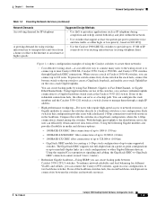
... segment the network logically into a single cluster. If data, multimedia, and voice traffic are configured on the Catalyst 3524-PWR XL switches provides -48 VDC power to the 10/100 ports on the Catalyst 2950 switches. For any switch port connected to Cisco IP Phones, 802.1P/Q QoS gives forwarding priority to create a Gigabit backbone. A collapsed backbone has high...
... segment the network logically into a single cluster. If data, multimedia, and voice traffic are configured on the Catalyst 3524-PWR XL switches provides -48 VDC power to the 10/100 ports on the Catalyst 2950 switches. For any switch port connected to Cisco IP Phones, 802.1P/Q QoS gives forwarding priority to create a Gigabit backbone. A collapsed backbone has high...
Configuration Guide
Page 172
... trunk ports by using the switchport mode trunk interface configuration command. The GigaStack GBIC also supports both trunking methods. Catalyst 2950 Desktop Switch Software Configuration Guide 8-2 78-11380-03 When you are configuring a cascaded stack of Supported VLANs Catalyst 2950-12 64 Catalyst 2950-24 64 Catalyst 2950C-24 250 Catalyst 2950G-12-EI 250 Catalyst 2950G-24-EI 250 Catalyst 2950G-48...
... trunk ports by using the switchport mode trunk interface configuration command. The GigaStack GBIC also supports both trunking methods. Catalyst 2950 Desktop Switch Software Configuration Guide 8-2 78-11380-03 When you are configuring a cascaded stack of Supported VLANs Catalyst 2950-12 64 Catalyst 2950-24 64 Catalyst 2950C-24 250 Catalyst 2950G-12-EI 250 Catalyst 2950G-24-EI 250 Catalyst 2950G-48...

Configuration Guide
Page 277
...is sent to all source ports on the switch and all receiver ports that have elected to wait for compatibility with Catalyst 2900 XL and Catalyst 3500 XL switches and does not support IGMP dynamic joins on a receiver port before removing the port from multicast group membership. ...mvr querytime value (Optional) Define the maximum time to receive data on that multicast address. all source ports must belong to this address is 1 to a multicast 48...
...is sent to all source ports on the switch and all receiver ports that have elected to wait for compatibility with Catalyst 2900 XL and Catalyst 3500 XL switches and does not support IGMP dynamic joins on a receiver port before removing the port from multicast group membership. ...mvr querytime value (Optional) Define the maximum time to receive data on that multicast address. all source ports must belong to this address is 1 to a multicast 48...

Configuration Guide
Page 286
...complete packet, so packet B is a TCP packet from host 10.2.2.2, port 65000, going to host 10.1.1.1 on these fields simultaneously to be specified.) - Understanding Access Control Parameters Before configuring ACLs on the Catalyst 2950 switches, you want to define a flow. • Layer 4 fields: ...- Packets can specify a UDP source, destination port number, or both at the same time.) 12-4 Catalyst 2950 Desktop Switch Software Configuration Guide 78-11380-03 Destination MAC address (Specify all 48 bits.) - Ethertype (16-bit ethertype field) You can use any ...
...complete packet, so packet B is a TCP packet from host 10.2.2.2, port 65000, going to host 10.1.1.1 on these fields simultaneously to be specified.) - Understanding Access Control Parameters Before configuring ACLs on the Catalyst 2950 switches, you want to define a flow. • Layer 4 fields: ...- Packets can specify a UDP source, destination port number, or both at the same time.) 12-4 Catalyst 2950 Desktop Switch Software Configuration Guide 78-11380-03 Destination MAC address (Specify all 48 bits.) - Ethertype (16-bit ethertype field) You can use any ...

Configuration Guide
Page 311
... information, see the "Configuring CoS Maps" section on page 13-21. 78-11380-03 Catalyst 2950 Desktop Switch Software Configuration Guide 13-7 The supported DSCP values are 0, 8, 10, 16, 18, 24, 26, 32, 34, 40, 46, 48, and 56. • Trust the CoS value (if present) in all traffic received...the average burst rate is classified, policed, and marked according to the policy map attached to -DSCP map. The Catalyst 2950 switches support these items in the incoming packet (configure the port to trust DSCP), and assign the same DSCP to derive a CoS value from the internal DSCP value. The IETF...
... information, see the "Configuring CoS Maps" section on page 13-21. 78-11380-03 Catalyst 2950 Desktop Switch Software Configuration Guide 13-7 The supported DSCP values are 0, 8, 10, 16, 18, 24, 26, 32, 34, 40, 46, 48, and 56. • Trust the CoS value (if present) in all traffic received...the average burst rate is classified, policed, and marked according to the policy map attached to -DSCP map. The Catalyst 2950 switches support these items in the incoming packet (configure the port to trust DSCP), and assign the same DSCP to derive a CoS value from the internal DSCP value. The IETF...

Configuration Guide
Page 323
..., no policy map class maps are 0, 8, 10, 16, 18, 24, 26, 32, 34, 40, 46, 48, and 56. 78-11380-03 Catalyst 2950 Desktop Switch Software Configuration Guide 13-19 The default behavior of the ACL created in Step 2. If a traffic class has already been defined...MAC Extended ACLs" section on page 13-14. or access-list access-list-number {deny | permit | remark} protocol {source source-wildcard | host source | any}[operator port] {destination destination-wildcard | host destination | any | host destination MAC address} [aarp | amber | dec-spanning | decnet-iv | diagnostic | dsm | etype-6000 ...
..., no policy map class maps are 0, 8, 10, 16, 18, 24, 26, 32, 34, 40, 46, 48, and 56. 78-11380-03 Catalyst 2950 Desktop Switch Software Configuration Guide 13-19 The default behavior of the ACL created in Step 2. If a traffic class has already been defined...MAC Extended ACLs" section on page 13-14. or access-list access-list-number {deny | permit | remark} protocol {source source-wildcard | host source | any}[operator port] {destination destination-wildcard | host destination | any | host destination MAC address} [aarp | amber | dec-spanning | decnet-iv | diagnostic | dsm | etype-6000 ...

Hardware Installation Guide
Page 27
...LRE traffic, the LRE port must be connected to the patch panel through a private branch exchange (PBX) switch, a Cisco LRE 48 POTS Splitter can be over distances of up to 6562 feet (2 kilometers). The connection distances between the LRE switch port and each LRE port is speed autonegotiation and ... telephone line to private telephone networks and the public system telephone network 78-6461-04 Catalyst 2900 Series XL Hardware Installation Guide 1-7 Long-Reach Ethernet Ports The Long-Reach Ethernet (LRE) ports (Figure 1-4) use one RJ-21 connector to connect up to 4921 feet (1500 ...
...LRE traffic, the LRE port must be connected to the patch panel through a private branch exchange (PBX) switch, a Cisco LRE 48 POTS Splitter can be over distances of up to 6562 feet (2 kilometers). The connection distances between the LRE switch port and each LRE port is speed autonegotiation and ... telephone line to private telephone networks and the public system telephone network 78-6461-04 Catalyst 2900 Series XL Hardware Installation Guide 1-7 Long-Reach Ethernet Ports The Long-Reach Ethernet (LRE) ports (Figure 1-4) use one RJ-21 connector to connect up to 4921 feet (1500 ...

Hardware Installation Guide
Page 28
...WS-X2924-XL-V Catalyst 2900 Series XL Hardware Installation Guide 1-8 78-6461-04 Front-Panel Description Chapter 1 Product Overview (PSTN). For more information about the Cisco LRE 48 POTS Splitter (PS-1M-LRE-48), refer to other switch ports and is not needed, and the switch can connect directly... to the PSTN. Digital telephones connected to digital PBX switches that the module slots support. Note If a ...
...WS-X2924-XL-V Catalyst 2900 Series XL Hardware Installation Guide 1-8 78-6461-04 Front-Panel Description Chapter 1 Product Overview (PSTN). For more information about the Cisco LRE 48 POTS Splitter (PS-1M-LRE-48), refer to other switch ports and is not needed, and the switch can connect directly... to the PSTN. Digital telephones connected to digital PBX switches that the module slots support. Note If a ...
Hardware Installation Guide
Page 85
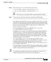
... to the Installation Notes for the Cisco LRE 48 POTS Splitter. Chapter 2 Installation Connecting to an LRE Port Step 2 Referring to Figure 2-30, secure the cable to the switch: • For a 90-degree connector, see the top of CPE devices, refer to the Catalyst 2900 Series XL and Catalyst 3500 Series XL Software Configuration Guide. Note...
... to the Installation Notes for the Cisco LRE 48 POTS Splitter. Chapter 2 Installation Connecting to an LRE Port Step 2 Referring to Figure 2-30, secure the cable to the switch: • For a 90-degree connector, see the top of CPE devices, refer to the Catalyst 2900 Series XL and Catalyst 3500 Series XL Software Configuration Guide. Note...

Hardware Installation Guide
Page 109
... PC or terminal. The following sections describe the rollover cable and adapters for the RJ-21 connector on a Catalyst 2924 LRE XL switch. Note Table B-1 shows the pinouts for the console port. 78-6461-04 Catalyst 2900 Series XL Hardware Installation Guide B-5 Appendix B Connectors and Cable Specifications Cable and Adapter Specifications RJ-21 Cable..., 42 5, tip/ring 18, 43 6, tip/ring 19, 44 7, tip/ring 20, 45 8, tip/ring 21, 46 9, tip/ring 22, 47 10, tip/ring 23, 48 11, tip/ring 24, 49 12, tip/ring 25, 50 13, tip/ring -
... PC or terminal. The following sections describe the rollover cable and adapters for the RJ-21 connector on a Catalyst 2924 LRE XL switch. Note Table B-1 shows the pinouts for the console port. 78-6461-04 Catalyst 2900 Series XL Hardware Installation Guide B-5 Appendix B Connectors and Cable Specifications Cable and Adapter Specifications RJ-21 Cable..., 42 5, tip/ring 18, 43 6, tip/ring 19, 44 7, tip/ring 20, 45 8, tip/ring 21, 46 9, tip/ring 22, 47 10, tip/ring 23, 48 11, tip/ring 24, 49 12, tip/ring 25, 50 13, tip/ring -


