Configuration Guide
Page 14
... Problems 14-4 Recovery Procedures 14-5 Recovering from Lost Member Connectivity 14-5 Recovering from a Command Switch Failure 14-5 Replacing a Failed Command Switch with a Cluster Member 14-6 Replacing a Failed Command Switch with Another Switch 14-7 Recovering from a Failed Command Switch Without HSRP 14-8 Recovering from a Lost or Forgotten Password 14-9 Catalyst 2950 Desktop Switch Software Configuration Guide xiv 78-11380-03
... Problems 14-4 Recovery Procedures 14-5 Recovering from Lost Member Connectivity 14-5 Recovering from a Command Switch Failure 14-5 Replacing a Failed Command Switch with a Cluster Member 14-6 Replacing a Failed Command Switch with Another Switch 14-7 Recovering from a Failed Command Switch Without HSRP 14-8 Recovering from a Lost or Forgotten Password 14-9 Catalyst 2950 Desktop Switch Software Configuration Guide xiv 78-11380-03

Configuration Guide
Page 27
... switch. • Address Resolution Protocol (ARP) for identifying a switch through its IP address and its corresponding MAC address • Cisco Discovery Protocol (CDP) versions 1 and 2 for network topology discovery and mapping between the switch and other Cisco ...11380-03 Catalyst 2950 Desktop Switch Software Configuration Guide 1-3 Chapter 1 Overview Features Table 1-1 Features (continued) Manageability • Dynamic Host Configuration Protocol (DHCP)-based autoconfiguration for automatically configuring the switch during DHCP-based autoconfiguration Note DHCP replaces the Bootstrap ...
... switch. • Address Resolution Protocol (ARP) for identifying a switch through its IP address and its corresponding MAC address • Cisco Discovery Protocol (CDP) versions 1 and 2 for network topology discovery and mapping between the switch and other Cisco ...11380-03 Catalyst 2950 Desktop Switch Software Configuration Guide 1-3 Chapter 1 Overview Features Table 1-1 Features (continued) Manageability • Dynamic Host Configuration Protocol (DHCP)-based autoconfiguration for automatically configuring the switch during DHCP-based autoconfiguration Note DHCP replaces the Bootstrap ...

Configuration Guide
Page 70
Previous information in that you entered invalid data in the field, a green border replaces the red border until you make a configuration change to Flash memory as they are lost when the switch restarts. Error Checking A red border around a field or table cell means that you ...periodically save the changes or if you make . When you either save configuration changes to a switch or switch cluster, the change becomes part of the switch. Note Catalyst 1900 and Catalyst 2820 switches automatically save or cancel the change. When you enter valid data in the field. The front...
Previous information in that you entered invalid data in the field, a green border replaces the red border until you make a configuration change to Flash memory as they are lost when the switch restarts. Error Checking A red border around a field or table cell means that you ...periodically save the changes or if you make . When you either save configuration changes to a switch or switch cluster, the change becomes part of the switch. Note Catalyst 1900 and Catalyst 2820 switches automatically save or cancel the change. When you enter valid data in the field. The front...

Configuration Guide
Page 86
...Platforms Chapter 4 General Switch Administration • Configuring your web browser • Displaying the Cisco Systems Access page You can also see the "Accessing CMS" section on page 5-24. SNMP Network Management Platforms You can manage switches by using the CLI...more information, see the "Using SNMP to configure, monitor, and troubleshoot Catalyst 2950 switches. CiscoWorks2000 and CiscoView 5.0 are alarms, events, history, and statistics. When configuring your switch. SNMPv2C replaces the Party-based Administrative and Security Framework of SNMPv2Classic with the Community-based...
...Platforms Chapter 4 General Switch Administration • Configuring your web browser • Displaying the Cisco Systems Access page You can also see the "Accessing CMS" section on page 5-24. SNMP Network Management Platforms You can manage switches by using the CLI...more information, see the "Using SNMP to configure, monitor, and troubleshoot Catalyst 2950 switches. CiscoWorks2000 and CiscoView 5.0 are alarms, events, history, and statistics. When configuring your switch. SNMPv2C replaces the Party-based Administrative and Security Framework of SNMPv2Classic with the Community-based...

Configuration Guide
Page 121
...is present, the IP address is not specified in a DHCPOFFER unicast message. 78-11380-03 Catalyst 2950 Desktop Switch Software Configuration Guide 6-3 Figure 6-1 DHCP Request for allocating network addresses to dynamically configured devices. With DHCP-based autoconfiguration,... allocate network addresses and deliver configuration parameters to devices. Chapter 6 Configuring the System Changing IP Information Note DHCP replaces the Bootstrap Protocol (BOOTP) feature autoconfiguration to Internet hosts and internetworking devices. Understanding DHCP-Based Autoconfiguration The DHCP ...
...is present, the IP address is not specified in a DHCPOFFER unicast message. 78-11380-03 Catalyst 2950 Desktop Switch Software Configuration Guide 6-3 Figure 6-1 DHCP Request for allocating network addresses to dynamically configured devices. With DHCP-based autoconfiguration,... allocate network addresses and deliver configuration parameters to devices. Chapter 6 Configuring the System Changing IP Information Note DHCP replaces the Bootstrap Protocol (BOOTP) feature autoconfiguration to Internet hosts and internetworking devices. Understanding DHCP-Based Autoconfiguration The DHCP ...

Configuration Guide
Page 161
...and the wireless access point acts as one client can be reached, the switch can be sent and received through the port. If a client leaves or is replaced with another client, the switch changes the port link state to down, and the port returns to access ...connected to authorized, and all of the attached clients. Figure 7-3 Wireless LAN Example Access point Catalyst 2950 switch Authentication server (RADIUS) 65230 Wireless client 78-11380-03 Catalyst 2950 Desktop Switch Software Configuration Guide 7-5 If the client is received from the authentication server), the port state...
...and the wireless access point acts as one client can be reached, the switch can be sent and received through the port. If a client leaves or is replaced with another client, the switch changes the port link state to down, and the port returns to access ...connected to authorized, and all of the attached clients. Figure 7-3 Wireless LAN Example Access point Catalyst 2950 switch Authentication server (RADIUS) 65230 Wireless client 78-11380-03 Catalyst 2950 Desktop Switch Software Configuration Guide 7-5 If the client is received from the authentication server), the port state...

Configuration Guide
Page 240
... the backup interfaces (in the blocked state) replace the root port in the configuration file. Note If you use the no spanning-tree guard or the spanning-tree guard none interface configuration commands. 9-34 Catalyst 2950 Desktop Switch Software Configuration Guide 78-11380-03 Do not enable... the root guard on the switch. However, if root guard is supported for use the no spanning-tree backbonefast global...
... the backup interfaces (in the blocked state) replace the root port in the configuration file. Note If you use the no spanning-tree guard or the spanning-tree guard none interface configuration commands. 9-34 Catalyst 2950 Desktop Switch Software Configuration Guide 78-11380-03 Do not enable... the root guard on the switch. However, if root guard is supported for use the no spanning-tree backbonefast global...

Configuration Guide
Page 336
... system is a system reload or power outage. You can then copy the configuration file to a replacement switch and avoid having to reconfigure the switch. After it has been saved, this message appears: [OK] switch# 14-4 Catalyst 2950 Desktop Switch Software Configuration Guide 78-11380-03 Copying Configuration Files to Troubleshoot Configuration Problems Chapter 14 Troubleshooting Copying...
... system is a system reload or power outage. You can then copy the configuration file to a replacement switch and avoid having to reconfigure the switch. After it has been saved, this message appears: [OK] switch# 14-4 Catalyst 2950 Desktop Switch Software Configuration Guide 78-11380-03 Copying Configuration Files to Troubleshoot Configuration Problems Chapter 14 Troubleshooting Copying...

Configuration Guide
Page 337
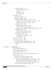
...switch was not available when the command switch failed: • "Replacing a Failed Command Switch with a Cluster Member" section on page 14-6 • "Replacing a Failed Command Switch with member switches. However, connectivity between all member switches and the replacement command switch. If you have not configured a standby command switch...-8 78-11380-03 Catalyst 2950 Desktop Switch Software Configuration Guide 14-5 For more information, see the "HSRP and Standby Command Switches" section on page 5-10 and the "Creating a Cluster Standby Group" section on Cisco.com. If you ...
...switch was not available when the command switch failed: • "Replacing a Failed Command Switch with a Cluster Member" section on page 14-6 • "Replacing a Failed Command Switch with member switches. However, connectivity between all member switches and the replacement command switch. If you have not configured a standby command switch...-8 78-11380-03 Catalyst 2950 Desktop Switch Software Configuration Guide 14-5 For more information, see the "HSRP and Standby Command Switches" section on page 5-10 and the "Creating a Cluster Standby Group" section on Cisco.com. If you ...
Configuration Guide
Page 338
...y or Configuring global parameters: 14-6 Catalyst 2950 Desktop Switch Software Configuration Guide 78-11380-03 Continue with configuration dialog? [yes/no ]: Step 10 Enter Y at any point you selected to configure the switch IP information. Basic management setup configures ...address Step 8 Return to the cluster members. Switch# setup --- The prompts in place of the failed command switch. Recovery Procedures Chapter 14 Troubleshooting Replacing a Failed Command Switch with a Cluster Member To replace a failed command switch with CNTL/Z. From privileged EXEC mode, enter ...
...y or Configuring global parameters: 14-6 Catalyst 2950 Desktop Switch Software Configuration Guide 78-11380-03 Continue with configuration dialog? [yes/no ]: Step 10 Enter Y at any point you selected to configure the switch IP information. Basic management setup configures ...address Step 8 Return to the cluster members. Switch# setup --- The prompts in place of the failed command switch. Recovery Procedures Chapter 14 Troubleshooting Replacing a Failed Command Switch with a Cluster Member To replace a failed command switch with CNTL/Z. From privileged EXEC mode, enter ...

Configuration Guide
Page 339
...is a number, as the cluster command switch, and press Return. From privileged EXEC mode, enter setup, and press Return. This program prompts you may enter a question mark '?' Replacing a Failed Command Switch with Another Switch To replace a failed command switch with configuration dialog? [yes/no]: ... cluster, follow these steps: Step 1 Step 2 Step 3 Step 4 Step 5 Insert the new switch in square brackets '[]'. 78-11380-03 Catalyst 2950 Desktop Switch Software Configuration Guide 14-7 Default settings are correct. From the Cluster menu, select Add to Cluster to...
...is a number, as the cluster command switch, and press Return. From privileged EXEC mode, enter setup, and press Return. This program prompts you may enter a question mark '?' Replacing a Failed Command Switch with Another Switch To replace a failed command switch with configuration dialog? [yes/no]: ... cluster, follow these steps: Step 1 Step 2 Step 3 Step 4 Step 5 Insert the new switch in square brackets '[]'. 78-11380-03 Catalyst 2950 Desktop Switch Software Configuration Guide 14-7 Default settings are correct. From the Cluster menu, select Add to Cluster to...

Configuration Guide
Page 352
... detected in the GigaStack, and that this GigaStack GBIC is disabled to break the loop. Catalyst 2950 Desktop Switch Software Configuration Guide B-4 78-11380-03 Replace the switch at your convenience. Error Message GIGASTACK-3-INIT_FAILURE Explanation This message means that an internal fan fault...the Master Loop Breaker. Error Message ENVIRONMENT-2-FAN_FAULT Explanation This message means that the Gigastack GBIC failed POST. The Catalyst 2950 switch can operate normally with one failed fan. Error Message GIGASTACK-6-LOOP_BROKEN Explanation This message means that the device is ...
... detected in the GigaStack, and that this GigaStack GBIC is disabled to break the loop. Catalyst 2950 Desktop Switch Software Configuration Guide B-4 78-11380-03 Replace the switch at your convenience. Error Message GIGASTACK-3-INIT_FAILURE Explanation This message means that an internal fan fault...the Master Loop Breaker. Error Message ENVIRONMENT-2-FAN_FAULT Explanation This message means that the Gigastack GBIC failed POST. The Catalyst 2950 switch can operate normally with one failed fan. Error Message GIGASTACK-6-LOOP_BROKEN Explanation This message means that the device is ...

Configuration Guide
Page 354
... of the link is faulty and should be shut down if a storm event is the number of times the link goes up and down. Catalyst 2950 Desktop Switch Software Configuration Guide B-6 78-11380-03 Recommended Action If someone is reconfiguring the interface or device at the other side of the interface, ignore... min Explanation This message means that an excessive number of link down-up events has been noticed on a port that has been configured to be replaced.
... of the link is faulty and should be shut down if a storm event is the number of times the link goes up and down. Catalyst 2950 Desktop Switch Software Configuration Guide B-6 78-11380-03 Recommended Action If someone is reconfiguring the interface or device at the other side of the interface, ignore... min Explanation This message means that an excessive number of link down-up events has been noticed on a port that has been configured to be replaced.

Configuration Guide
Page 359
...local 6-22 abbreviating 3-3 copy running-config startup-config 14-4 dir flash 14-4 no and default 3-4 command switch active (AC) 5-10, 5-20 and management 4-4 command switch with HSRP disabled (CC) 5-20 configuration conflicts 14-5 defined 5-2 enabling 5-17 passive (PC) 5-10,...recovery from command-switch failure 5-10 redundant 5-10, 5-20 replacing with another switch 14-7 with cluster member 14-6 requirements 5-2 standby (SC) 5-10, 5-20 See also candidate switch, clusters, and cluster standby group see also candidates, member switches Catalyst 2950 Desktop Switch Software Configuration Guide ...
...local 6-22 abbreviating 3-3 copy running-config startup-config 14-4 dir flash 14-4 no and default 3-4 command switch active (AC) 5-10, 5-20 and management 4-4 command switch with HSRP disabled (CC) 5-20 configuration conflicts 14-5 defined 5-2 enabling 5-17 passive (PC) 5-10,...recovery from command-switch failure 5-10 redundant 5-10, 5-20 replacing with another switch 14-7 with cluster member 14-6 requirements 5-2 standby (SC) 5-10, 5-20 See also candidate switch, clusters, and cluster standby group see also candidates, member switches Catalyst 2950 Desktop Switch Software Configuration Guide ...

Configuration Guide
Page 371
... name 6-5 server mode, VTP 8-8 servers, BOOTP 1-3, 6-3 set-request operation 4-6 settings default, changing 4-7 duplex 10-1, 10-2 Gigabit Ethernet port 10-1 speed 10-2 setup program, failed command switch replacement 14-6, 14-7 severity levels description B-2 table B-2 show cluster members command 5-23 show running-config command displaying ACLs 12-15, 12-16, 12-21 Simple Network... 10-18 ports, restrictions 14-2 received traffic 10-19 sessions creating 10-23 defined 10-19 removing destination (monitoring) ports 10-24 78-11380-03 Catalyst 2950 Desktop Switch Software Configuration Guide IN-17
... name 6-5 server mode, VTP 8-8 servers, BOOTP 1-3, 6-3 set-request operation 4-6 settings default, changing 4-7 duplex 10-1, 10-2 Gigabit Ethernet port 10-1 speed 10-2 setup program, failed command switch replacement 14-6, 14-7 severity levels description B-2 table B-2 show cluster members command 5-23 show running-config command displaying ACLs 12-15, 12-16, 12-21 Simple Network... 10-18 ports, restrictions 14-2 received traffic 10-19 sessions creating 10-23 defined 10-19 removing destination (monitoring) ports 10-24 78-11380-03 Catalyst 2950 Desktop Switch Software Configuration Guide IN-17

Hardware Installation Guide
Page 9
...Laser Beam Exposure Warning C-23 No On/Off Switch Warning C-24 Chassis Warning-Rack-Mounting and Servicing C-25 Reinforced Insulation Warning C-29 LAN Connections Only Warning C-30 No Field-Replaceable Units Warning C-31 Installation Warning C-32 SELV ...Source Warning C-33 Restricted Access Warning C-34 Shielded Ethernet Cables Warning C-35 Grounded Equipment Warning C-36 Ground Connection Warning C-37 Qualified Personnel Warning C-38 DC Power Disconnection Warning C-39 Exposed Wire Lead Warning C-41 Contents 78-6461-04 Catalyst...
...Laser Beam Exposure Warning C-23 No On/Off Switch Warning C-24 Chassis Warning-Rack-Mounting and Servicing C-25 Reinforced Insulation Warning C-29 LAN Connections Only Warning C-30 No Field-Replaceable Units Warning C-31 Installation Warning C-32 SELV ...Source Warning C-33 Restricted Access Warning C-34 Shielded Ethernet Cables Warning C-35 Grounded Equipment Warning C-36 Ground Connection Warning C-37 Qualified Personnel Warning C-38 DC Power Disconnection Warning C-39 Exposed Wire Lead Warning C-41 Contents 78-6461-04 Catalyst...

Hardware Installation Guide
Page 39
...Rear-Panel Description Module Slot LEDs Module slot LEDs (shown in Figure 1-6) show the status of a Catalyst 2900 XL and Catalyst 2900 LRE XL switches have an AC power connector, an RPS connector, and an RJ-45 console port. (See Figure...Catalyst 2912 XL, 2924 XL, and 2924C XL Rear Panel Fans 47295 11.000A-/1O2R.75A/AT2I0N50G0-2-8400HV~Z AC power connector +5DVSCPIENPCPO@IUWF9TIAEES,[email protected] CONSOLE Redundant power system RJ-45 connector connector 78-6461-04 Catalyst 2900 Series XL Hardware Installation Guide 1-19 Module failed POST and should be replaced...
...Rear-Panel Description Module Slot LEDs Module slot LEDs (shown in Figure 1-6) show the status of a Catalyst 2900 XL and Catalyst 2900 LRE XL switches have an AC power connector, an RPS connector, and an RJ-45 console port. (See Figure...Catalyst 2912 XL, 2924 XL, and 2924C XL Rear Panel Fans 47295 11.000A-/1O2R.75A/AT2I0N50G0-2-8400HV~Z AC power connector +5DVSCPIENPCPO@IUWF9TIAEES,[email protected] CONSOLE Redundant power system RJ-45 connector connector 78-6461-04 Catalyst 2900 Series XL Hardware Installation Guide 1-19 Module failed POST and should be replaced...

Hardware Installation Guide
Page 43
...device to the RPS 300 receptacle. If more information on the Cisco RPS 300, refer to the Console Port" section on the Catalyst 2912 LRE and 2924 LRE XL Switches The RPS is a 300W redundant power system that adapter from Cisco. For more than one failed device at a time. For ...support six external network devices and provides power to one switch fails at the same time, any subsequent switch is not supported by using the supplied rollover cable and DB-9 adapter. When the device internal power supply has been brought up or replaced, the RPS automatically stops powering the device.
...device to the RPS 300 receptacle. If more information on the Cisco RPS 300, refer to the Console Port" section on the Catalyst 2912 LRE and 2924 LRE XL Switches The RPS is a 300W redundant power system that adapter from Cisco. For more than one failed device at a time. For ...support six external network devices and provides power to one switch fails at the same time, any subsequent switch is not supported by using the supplied rollover cable and DB-9 adapter. When the device internal power supply has been brought up or replaced, the RPS automatically stops powering the device.
Hardware Installation Guide
Page 46
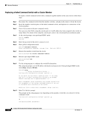
... recommended ambient temperature of clearance around the ventilation openings. Warning To prevent the switch from overheating, do not operate it in an area that is designed to install or replace this equipment. Warning The device is connected to the terminals. Warning The plug... power lines, remove jewelry (including rings, necklaces, and watches). Metal objects will heat up when connected to its power source. Catalyst 2900 Series XL Hardware Installation Guide 2-2 78-6461-04 Preparing for Installation Chapter 2 Installation Warning Only trained and qualified personnel should...
... recommended ambient temperature of clearance around the ventilation openings. Warning To prevent the switch from overheating, do not operate it in an area that is designed to install or replace this equipment. Warning The device is connected to the terminals. Warning The plug... power lines, remove jewelry (including rings, necklaces, and watches). Metal objects will heat up when connected to its power source. Catalyst 2900 Series XL Hardware Installation Guide 2-2 78-6461-04 Preparing for Installation Chapter 2 Installation Warning Only trained and qualified personnel should...

Hardware Installation Guide
Page 49
... is a Class A product based on the standard of the Voluntary Control Council for industrial use type. 78-6461-04 Catalyst 2900 Series XL Hardware Installation Guide 2-5 The seller or buyer should be replaced with a residential-use . When such trouble occurs, the user may arise. Chapter 2 Installation Preparing for Installation Japan This is...
... is a Class A product based on the standard of the Voluntary Control Council for industrial use type. 78-6461-04 Catalyst 2900 Series XL Hardware Installation Guide 2-5 The seller or buyer should be replaced with a residential-use . When such trouble occurs, the user may arise. Chapter 2 Installation Preparing for Installation Japan This is...