Configuration Guide
Page 33
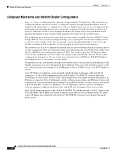
..., use a stack of Catalyst 2950-48 switches, you can create backup paths between the switches and network resources. 78-11380-03 Catalyst 2950 Desktop Switch Software Configuration Guide 1-9 Chapter...following Gigabit modules also provides flexibility in the backbone. Using the required Cisco proprietary signaling and cabling, the GigaStack GBIC-to-GigaStack GBIC connection cannot... based on two of the backbone switches fails, the second backbone switch preserves connectivity between Catalyst 3550-12T-L3 switches. To preserve switch connectivity if one full-duplex link (...
..., use a stack of Catalyst 2950-48 switches, you can create backup paths between the switches and network resources. 78-11380-03 Catalyst 2950 Desktop Switch Software Configuration Guide 1-9 Chapter...following Gigabit modules also provides flexibility in the backbone. Using the required Cisco proprietary signaling and cabling, the GigaStack GBIC-to-GigaStack GBIC connection cannot... based on two of the backbone switches fails, the second backbone switch preserves connectivity between Catalyst 3550-12T-L3 switches. To preserve switch connectivity if one full-duplex link (...
Configuration Guide
Page 36
...(such as a call processing, routing, and IP phone features and configuration. You can place, receive, and control calls from all the Catalyst switches except the Catalyst 4908G-L3 switch. Cisco IP Phones are connected-using standard straight-through the IP address of its active and standby command... multicast server). Each 10/100 inline-power port on the Catalyst 3524-PWR XL switches provides -48 VDC power to voice traffic over data traffic. IP phones not connected to the Catalyst 3524-PWR XL switches receive power from the Cisco IP Phones are assigned to the same VLAN, only one ...
...(such as a call processing, routing, and IP phone features and configuration. You can place, receive, and control calls from all the Catalyst switches except the Catalyst 4908G-L3 switch. Cisco IP Phones are connected-using standard straight-through the IP address of its active and standby command... multicast server). Each 10/100 inline-power port on the Catalyst 3524-PWR XL switches provides -48 VDC power to voice traffic over data traffic. IP phones not connected to the Catalyst 3524-PWR XL switches receive power from the Cisco IP Phones are assigned to the same VLAN, only one ...

Configuration Guide
Page 218
... configurations. Understanding Advanced STP Features Chapter 9 Configuring STP Figure 9-6 UplinkFast Example Before Direct Link Failure Switch A (Root) Switch B L1 L2 L3 Blocked port 43575 Switch C If Switch C detects a link failure on the currently active link L2 on the root port (a direct link... failure), UplinkFast unblocks the blocked port on page 9-14. 9-12 Catalyst 2950 Desktop Switch Software Configuration Guide 78-11380-...
... configurations. Understanding Advanced STP Features Chapter 9 Configuring STP Figure 9-6 UplinkFast Example Before Direct Link Failure Switch A (Root) Switch B L1 L2 L3 Blocked port 43575 Switch C If Switch C detects a link failure on the currently active link L2 on the root port (a direct link... failure), UplinkFast unblocks the blocked port on page 9-14. 9-12 Catalyst 2950 Desktop Switch Software Configuration Guide 78-11380-...

Configuration Guide
Page 223
...times on the ports on which it has lost its designated bridge. This 78-11380-03 Catalyst 2950 Desktop Switch Software Configuration Guide 9-17 Switch A, the root switch, connects directly to Switch B over link L2. If the inferior BPDU arrives on the root port and there ... and learning states, and into the forwarding state. If one switch as the root. Figure 9-10 BackboneFast Example Before Indirect Link Failure Switch A (Root) Switch B L1 L2 L3 Blocked port 44963 Switch C If link L1 fails, Switch C cannot detect this failure because it means that an indirect ...
...times on the ports on which it has lost its designated bridge. This 78-11380-03 Catalyst 2950 Desktop Switch Software Configuration Guide 9-17 Switch A, the root switch, connects directly to Switch B over link L2. If the inferior BPDU arrives on the root port and there ... and learning states, and into the forwarding state. If one switch as the root. Figure 9-10 BackboneFast Example Before Indirect Link Failure Switch A (Root) Switch B L1 L2 L3 Blocked port 44963 Switch C If link L1 fails, Switch C cannot detect this failure because it means that an indirect ...

Configuration Guide
Page 224
... Indirect Link Failure Switch A (Root) Switch B L1 Link failure L2 L3 Switch C BackboneFast transitions port through listening and learning states to Switch A, the root switch. Figure 9-12 Adding a Switch in Figure 9-12, BackboneFast is introduced into a shared-medium topology as shown in a Shared-Medium Topology Switch A (Root) Switch C Blocked port Switch B (Designated bridge) Added switch 44965 9-18 Catalyst 2950 Desktop Switch Software Configuration...
... Indirect Link Failure Switch A (Root) Switch B L1 Link failure L2 L3 Switch C BackboneFast transitions port through listening and learning states to Switch A, the root switch. Figure 9-12 Adding a Switch in Figure 9-12, BackboneFast is introduced into a shared-medium topology as shown in a Shared-Medium Topology Switch A (Root) Switch C Blocked port Switch B (Designated bridge) Added switch 44965 9-18 Catalyst 2950 Desktop Switch Software Configuration...