Chassis Replacement Instructions
Page 2
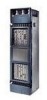
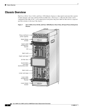
Chassis Overview Chassis Overview The Cisco 12016, Cisco 12416, and Cisco 12816 Router chassis is a separate unit that consists of the chassis. Figure 1 Cisco 12016, Cisco 12416, and Cisco 12816 Router (Front View, AC-Input Power Subsystem Shown) Power shelf and power supplies Upper blower module Upper cable management bracket RP Alarm card Upper card cage Air filter door Switch...
Chassis Overview Chassis Overview The Cisco 12016, Cisco 12416, and Cisco 12816 Router chassis is a separate unit that consists of the chassis. Figure 1 Cisco 12016, Cisco 12416, and Cisco 12816 Router (Front View, AC-Input Power Subsystem Shown) Power shelf and power supplies Upper blower module Upper cable management bracket RP Alarm card Upper card cage Air filter door Switch...
Chassis Replacement Instructions
Page 3
... network data and system communication across the internal system maintenance bus (MBus). Cooling The two removable blower modules at all cards in the upper card cage is reserved for the RP. The far right slot (slot...line card slots must be installed in their slots except during replacement. Nearly all the cards and blower modules in slot 8 of the lower card cage (slot 8). The chassis backplane distributes DC power to all... not equipped with four DC-input power entry modules (PEMs). 78-16082-01 Cisco 12016, Cisco 12416, and Cisco 12816 Router Chassis Replacement Instructions 3
... network data and system communication across the internal system maintenance bus (MBus). Cooling The two removable blower modules at all cards in the upper card cage is reserved for the RP. The far right slot (slot...line card slots must be installed in their slots except during replacement. Nearly all the cards and blower modules in slot 8 of the lower card cage (slot 8). The chassis backplane distributes DC power to all... not equipped with four DC-input power entry modules (PEMs). 78-16082-01 Cisco 12016, Cisco 12416, and Cisco 12816 Router Chassis Replacement Instructions 3
Chassis Replacement Instructions
Page 4
...area for compliance with electromagnetic compatibility (EMC) regulations. Preparing for system load zone 1 (the upper blower module and the upper card cage); Cisco 12016, Cisco 12416, and Cisco 12816 Router Chassis Replacement Instructions 4 78-16082-01 The AC-input power subsystem consists of the DC-input... Safety with Equipment • Always disconnect all power cords and interface cables before installing, configuring, or maintaining the router. Modules A2 and B2 provide redundant power for your work alone if potentially hazardous conditions exist. • Do not perform any ...
...area for compliance with electromagnetic compatibility (EMC) regulations. Preparing for system load zone 1 (the upper blower module and the upper card cage); Cisco 12016, Cisco 12416, and Cisco 12816 Router Chassis Replacement Instructions 4 78-16082-01 The AC-input power subsystem consists of the DC-input... Safety with Equipment • Always disconnect all power cords and interface cables before installing, configuring, or maintaining the router. Modules A2 and B2 provide redundant power for your work alone if potentially hazardous conditions exist. • Do not perform any ...
Chassis Replacement Instructions
Page 7
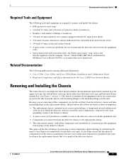
... an equivalent safety hand truck. Removing and Installing the Chassis Required Tools and Equipment The following publications contain additional information: • Cisco 12016, Cisco 12416, and Cisco 12816 Router Installation and Configuration Guide • Regulatory Compliance and Safety Information for use in removing the defective chassis from the equipment ... the upper card cage, the switch fabric card cage and air filter door, the lower card cage, and the lower blower module bay. (see Figure 1 on page 2.) The chassis is mounted in an equipment rack by ten screws (five on each ...
... an equivalent safety hand truck. Removing and Installing the Chassis Required Tools and Equipment The following publications contain additional information: • Cisco 12016, Cisco 12416, and Cisco 12816 Router Installation and Configuration Guide • Regulatory Compliance and Safety Information for use in removing the defective chassis from the equipment ... the upper card cage, the switch fabric card cage and air filter door, the lower card cage, and the lower blower module bay. (see Figure 1 on page 2.) The chassis is mounted in an equipment rack by ten screws (five on each ...
Chassis Replacement Instructions
Page 9
... supply is off. a. Turn off . Verify that the power fan in each blower module is off all circuit breakers for the source power lines connected to remove and the install the chassis. 78-16082-01 Cisco 12016, Cisco 12416, and Cisco 12816 Router Chassis Replacement Instructions 9 Verify that the LED labeled PWR OK on each...
... supply is off. a. Turn off . Verify that the power fan in each blower module is off all circuit breakers for the source power lines connected to remove and the install the chassis. 78-16082-01 Cisco 12016, Cisco 12416, and Cisco 12816 Router Chassis Replacement Instructions 9 Verify that the LED labeled PWR OK on each...
Chassis Replacement Instructions
Page 12
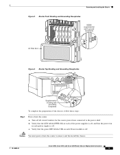
...Cisco 12416, and Cisco 12816 Router Installation and Configuration Guide for a second supplemental bonding and grounding connector (if present). Refer to any of the earth ground cable receptacles on the back of the power interface panel on the chassis, you must detach these steps: Step 1 Step 2 Step 3 Remove the blower modules... and grounding cables attached to the Cisco 12016, Cisco 12416, and Cisco 12816 Router Installation and Configuration Guide for detailed procedures. Refer to the Cisco 12016, Cisco 12416, and Cisco 12816 Router Installation and Configuration Guide for...
...Cisco 12416, and Cisco 12816 Router Installation and Configuration Guide for a second supplemental bonding and grounding connector (if present). Refer to any of the earth ground cable receptacles on the back of the power interface panel on the chassis, you must detach these steps: Step 1 Step 2 Step 3 Remove the blower modules... and grounding cables attached to the Cisco 12016, Cisco 12416, and Cisco 12816 Router Installation and Configuration Guide for detailed procedures. Refer to the Cisco 12016, Cisco 12416, and Cisco 12816 Router Installation and Configuration Guide for...
Chassis Replacement Instructions
Page 22
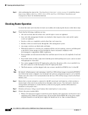
...slot 0 of the DC-input power shelf. • The Flash memory card that you have a remote login to the Cisco 12016, Cisco 12416, and Cisco 12816 Router Installation and Configuration Guide for detailed instructions. Checking Router Operation To restart the router and verify that it restarts ... panel is installed to ensure proper air flow through the chassis and proper compliance with electromagnetic compatibility (EMC) regulations. • Power modules are fully inserted in their bays and their ejector levers are all completely closed and secured. • Power shelf cables are secured ...
...slot 0 of the DC-input power shelf. • The Flash memory card that you have a remote login to the Cisco 12016, Cisco 12416, and Cisco 12816 Router Installation and Configuration Guide for detailed instructions. Checking Router Operation To restart the router and verify that it restarts ... panel is installed to ensure proper air flow through the chassis and proper compliance with electromagnetic compatibility (EMC) regulations. • Power modules are fully inserted in their bays and their ejector levers are all completely closed and secured. • Power shelf cables are secured ...
Chassis Replacement Instructions
Page 23
... the exhaust vents near the top and bottom rear of each side). 78-16082-01 Cisco 12016, Cisco 12416, and Cisco 12816 Router Chassis Replacement Instructions 23 the LED labeled FAIL should be on each blower module. If the power supplies do not power up, or if the system or any interfaces..., refer to verify that PEM. When the blower module is operating correctly, the green LED labeled OK should be off and the LED labeled PWR OK should be on the front of the chassis to the Cisco 12016, Cisco 12416, and Cisco 12816 Router Installation and Configuration Guide that shipped with ...
... the exhaust vents near the top and bottom rear of each side). 78-16082-01 Cisco 12016, Cisco 12416, and Cisco 12816 Router Chassis Replacement Instructions 23 the LED labeled FAIL should be on each blower module. If the power supplies do not power up, or if the system or any interfaces..., refer to verify that PEM. When the blower module is operating correctly, the green LED labeled OK should be off and the LED labeled PWR OK should be on the front of the chassis to the Cisco 12016, Cisco 12416, and Cisco 12816 Router Installation and Configuration Guide that shipped with ...


