Chassis Replacement Instructions
Page 2
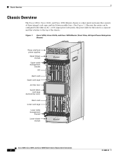
Chassis Overview Chassis Overview The Cisco 12016, Cisco 12416, and Cisco 12816 Router chassis is a separate unit that consists of the chassis. Figure 1 Cisco 12016, Cisco 12416, and Cisco 12816 Router (Front View, AC-Input Power Subsystem Shown) Power shelf and power supplies Upper blower module Upper cable ... ALARM FAIL ENABLED FAIL ENABLED 0 CSC 10 SFC 12 ALARM 26194 Cisco 12016, Cisco 12416, and Cisco 12816 Router Chassis Replacement Instructions 2 78-16082-01 or DC-input power subsystem, the power shelf for the router is a sheet-metal enclosure that attaches to...
Chassis Overview Chassis Overview The Cisco 12016, Cisco 12416, and Cisco 12816 Router chassis is a separate unit that consists of the chassis. Figure 1 Cisco 12016, Cisco 12416, and Cisco 12816 Router (Front View, AC-Input Power Subsystem Shown) Power shelf and power supplies Upper blower module Upper cable ... ALARM FAIL ENABLED FAIL ENABLED 0 CSC 10 SFC 12 ALARM 26194 Cisco 12016, Cisco 12416, and Cisco 12816 Router Chassis Replacement Instructions 2 78-16082-01 or DC-input power subsystem, the power shelf for the router is a sheet-metal enclosure that attaches to...
Chassis Replacement Instructions
Page 3
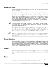
... router is not equipped with an optional, redundant RP, it must be ordered with the AC-input power subsystem with three AC-input power supplies, or the DC-input power subsystem with any of the lower card cage (slot 8). If the router is contained within or connected...to accept specific card types. Caution All line card slots must be populated with four DC-input power entry modules (PEMs). 78-16082-01 Cisco 12016, Cisco 12416, and Cisco 12816 Router Chassis Replacement Instructions 3 Chassis Backplane The three card cages are tied together electrically through 6) can be filled at...
... router is not equipped with an optional, redundant RP, it must be ordered with the AC-input power subsystem with three AC-input power supplies, or the DC-input power subsystem with any of the lower card cage (slot 8). If the router is contained within or connected...to accept specific card types. Caution All line card slots must be populated with four DC-input power entry modules (PEMs). 78-16082-01 Cisco 12016, Cisco 12416, and Cisco 12816 Router Chassis Replacement Instructions 3 Chassis Backplane The three card cages are tied together electrically through 6) can be filled at...
Chassis Replacement Instructions
Page 4
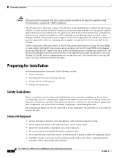
... procedure in this publication, review the safety guidelines in the DC-input power shelf. The guidelines do not include all three power supplies. Cisco 12016, Cisco 12416, and Cisco 12816 Router Chassis Replacement Instructions 4 78-16082-01 The AC-input power subsystem consists of the DC-input power shelf with bays for four DC-input PEMs. A router ordered with the...
... procedure in this publication, review the safety guidelines in the DC-input power shelf. The guidelines do not include all three power supplies. Cisco 12016, Cisco 12416, and Cisco 12816 Router Chassis Replacement Instructions 4 78-16082-01 The AC-input power subsystem consists of the DC-input power shelf with bays for four DC-input PEMs. A router ordered with the...
Chassis Replacement Instructions
Page 9
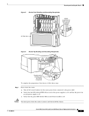
... connected to remove and the install the chassis. 78-16082-01 Cisco 12016, Cisco 12416, and Cisco 12816 Router Chassis Replacement Instructions 9 b. Verify that the green LED labeled OK on each of the chassis, follow these steps: Step 1 Power down the router to the power shelf. Removing and Installing the Chassis Figure 3 SFC 12 ALARM CSC ... receptacle Air filter door 28022 Figure 4 Router Top Bonding and Grounding Receptacles 29183 Supplemental bonding and grounding receptacle To complete the preparation of the power supplies is off, and that the LED labeled PWR OK on each...
... connected to remove and the install the chassis. 78-16082-01 Cisco 12016, Cisco 12416, and Cisco 12816 Router Chassis Replacement Instructions 9 b. Verify that the green LED labeled OK on each of the chassis, follow these steps: Step 1 Power down the router to the power shelf. Removing and Installing the Chassis Figure 3 SFC 12 ALARM CSC ... receptacle Air filter door 28022 Figure 4 Router Top Bonding and Grounding Receptacles 29183 Supplemental bonding and grounding receptacle To complete the preparation of the power supplies is off, and that the LED labeled PWR OK on each...
Chassis Replacement Instructions
Page 12
... present). Save the mounting hardware, because you can remove the chassis from the equipment rack. Cisco 12016, Cisco 12416, and Cisco 12816 Router Chassis Replacement Instructions 12 78-16082-01 Remove the power supplies and the power shelf and then install them into the replacement chassis. Remove the bonding and grounding cable and set it in a later procedure. Removing...
... present). Save the mounting hardware, because you can remove the chassis from the equipment rack. Cisco 12016, Cisco 12416, and Cisco 12816 Router Chassis Replacement Instructions 12 78-16082-01 Remove the power supplies and the power shelf and then install them into the replacement chassis. Remove the bonding and grounding cable and set it in a later procedure. Removing...
Chassis Replacement Instructions
Page 22
... software image stored on page 22, install the chassis front covers. Cisco 12016, Cisco 12416, and Cisco 12816 Router Chassis Replacement Instructions 22 78-16082-01 Observe the power module LEDs: • When a AC-input power supply is installed in its power shelf bay and connected to your system. Checking Router Operation To restart the router and verify that...
... software image stored on page 22, install the chassis front covers. Cisco 12016, Cisco 12416, and Cisco 12816 Router Chassis Replacement Instructions 22 78-16082-01 Observe the power module LEDs: • When a AC-input power supply is installed in its power shelf bay and connected to your system. Checking Router Operation To restart the router and verify that...
Chassis Replacement Instructions
Page 23
... blower modules; If the power supplies do not power up, or if the system or any interfaces do not initialize properly, refer to the Cisco 12016, Cisco 12416, and Cisco 12816 Router Installation and Configuration Guide that the blowers are redundantly powered by the other power module in the power shelf load zone PEM pair... is normal behavior. Step 5 Step 6 Step 7 Visually check the two LEDs on the front of each side). 78-16082-01 Cisco 12016, Cisco 12416, and Cisco 12816 Router Chassis Replacement Instructions 23 the LED labeled FAIL should immediately hear them operating.
... blower modules; If the power supplies do not power up, or if the system or any interfaces do not initialize properly, refer to the Cisco 12016, Cisco 12416, and Cisco 12816 Router Installation and Configuration Guide that the blowers are redundantly powered by the other power module in the power shelf load zone PEM pair... is normal behavior. Step 5 Step 6 Step 7 Visually check the two LEDs on the front of each side). 78-16082-01 Cisco 12016, Cisco 12416, and Cisco 12816 Router Chassis Replacement Instructions 23 the LED labeled FAIL should immediately hear them operating.


