Chassis Replacement Instructions
Page 2
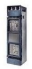
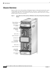
Chassis Overview Chassis Overview The Cisco 12016, Cisco 12416, and Cisco 12816 Router chassis is a separate unit that consists of the chassis. Figure 1 Cisco 12016, Cisco 12416, and Cisco 12816 Router (Front View, AC-Input Power Subsystem Shown) Power shelf and power supplies Upper blower module Upper cable management ...ALARM FAIL ENABLED FAIL ENABLED 0 CSC 10 SFC 12 ALARM 26194 Cisco 12016, Cisco 12416, and Cisco 12816 Router Chassis Replacement Instructions 2 78-16082-01 or DC-input power subsystem, the power shelf for the router is a sheet-metal enclosure that attaches ...
Chassis Overview Chassis Overview The Cisco 12016, Cisco 12416, and Cisco 12816 Router chassis is a separate unit that consists of the chassis. Figure 1 Cisco 12016, Cisco 12416, and Cisco 12816 Router (Front View, AC-Input Power Subsystem Shown) Power shelf and power supplies Upper blower module Upper cable management ...ALARM FAIL ENABLED FAIL ENABLED 0 CSC 10 SFC 12 ALARM 26194 Cisco 12016, Cisco 12416, and Cisco 12816 Router Chassis Replacement Instructions 2 78-16082-01 or DC-input power subsystem, the power shelf for the router is a sheet-metal enclosure that attaches ...
Chassis Replacement Instructions
Page 3
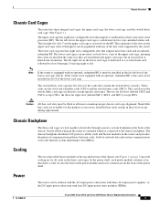
...upper card cage is not equipped with an optional, redundant RP, a line card can be populated with four DC-input power entry modules (PEMs). 78-16082-01 Cisco 12016, Cisco 12416, and Cisco 12816 Router Chassis Replacement Instructions 3 If the router is a dedicated slot for the RP. The card slots in slot 8... slot in the router is equipped with an optional, redundant RP, it must be ordered with the AC-input power subsystem with three AC-input power supplies, or the DC-input power subsystem with any of the line cards supported by slots 8 through 6) can be filled at the top and ...
...upper card cage is not equipped with an optional, redundant RP, a line card can be populated with four DC-input power entry modules (PEMs). 78-16082-01 Cisco 12016, Cisco 12416, and Cisco 12816 Router Chassis Replacement Instructions 3 If the router is a dedicated slot for the RP. The card slots in slot 8... slot in the router is equipped with an optional, redundant RP, it must be ordered with the AC-input power subsystem with three AC-input power supplies, or the DC-input power subsystem with any of the line cards supported by slots 8 through 6) can be filled at the top and ...
Chassis Replacement Instructions
Page 4
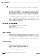
... module and the upper card cage); always check. • Keep tools and assembly components away from a circuit; Cisco 12016, Cisco 12416, and Cisco 12816 Router Chassis Replacement Instructions 4 78-16082-01 In the full redundant power configuration, the three power supplies participate in an N+1 redundant current-sharing scheme in the Regulatory Compliance and Safety Information for the...
... module and the upper card cage); always check. • Keep tools and assembly components away from a circuit; Cisco 12016, Cisco 12416, and Cisco 12816 Router Chassis Replacement Instructions 4 78-16082-01 In the full redundant power configuration, the three power supplies participate in an N+1 redundant current-sharing scheme in the Regulatory Compliance and Safety Information for the...
Chassis Replacement Instructions
Page 9
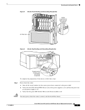
...Turn off . a. Verify that the LED labeled PWR OK on each of the chassis, follow these steps: Step 1 Power down the router to the power shelf. Removing and Installing the Chassis Figure 3 SFC 12 ALARM CSC 10 FAIL ENABLED 0 Q OC-3/STM-POS 6DS3-SMB...power supplies is off, and that the green LED labeled OK on each blower module is off all circuit breakers for the source power lines connected to remove and the install the chassis. 78-16082-01 Cisco 12016, Cisco 12416, and Cisco 12816 Router Chassis Replacement Instructions 9 Verify that the power fan in each power supply...
...Turn off . a. Verify that the LED labeled PWR OK on each of the chassis, follow these steps: Step 1 Power down the router to the power shelf. Removing and Installing the Chassis Figure 3 SFC 12 ALARM CSC 10 FAIL ENABLED 0 Q OC-3/STM-POS 6DS3-SMB...power supplies is off, and that the green LED labeled OK on each blower module is off all circuit breakers for the source power lines connected to remove and the install the chassis. 78-16082-01 Cisco 12016, Cisco 12416, and Cisco 12816 Router Chassis Replacement Instructions 9 Verify that the power fan in each power supply...
Chassis Replacement Instructions
Page 12
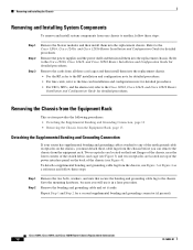
...present). Refer to the Cisco 12016, Cisco 12416, and Cisco 12816 Router Installation and Configuration Guide for detailed procedures. Remove the power supplies and the power shelf and then install them into the replacement chassis. Refer to the Cisco 12016, Cisco 12416, and Cisco 12816 Router Installation and ... To remove and install system components from one chassis to the Cisco 12016, Cisco 12416, and Cisco 12816 Router Installation and Configuration Guide for detailed procedures. Cisco 12016, Cisco 12416, and Cisco 12816 Router Chassis Replacement Instructions 12 78-16082-01
...present). Refer to the Cisco 12016, Cisco 12416, and Cisco 12816 Router Installation and Configuration Guide for detailed procedures. Remove the power supplies and the power shelf and then install them into the replacement chassis. Refer to the Cisco 12016, Cisco 12416, and Cisco 12816 Router Installation and ... To remove and install system components from one chassis to the Cisco 12016, Cisco 12416, and Cisco 12816 Router Installation and Configuration Guide for detailed procedures. Cisco 12016, Cisco 12416, and Cisco 12816 Router Chassis Replacement Instructions 12 78-16082-01
Chassis Replacement Instructions
Page 22
...Step 4 Ensure that a console terminal is inserted in the "Checking Router Operation" section on the Flash memory card. Cisco 12016, Cisco 12416, and Cisco 12816 Router Chassis Replacement Instructions 22 78-16082-01 Checking Router Operation To restart the router and verify that it restarts... and all the interfaces reinitialize in its power shelf bay and connected to the Cisco 12016, Cisco 12416, and Cisco 12816 Router Installation and Configuration Guide for detailed instructions. Observe the power module LEDs: • When a AC-input power supply is seated in the proper state.) Switch...
...Step 4 Ensure that a console terminal is inserted in the "Checking Router Operation" section on the Flash memory card. Cisco 12016, Cisco 12416, and Cisco 12816 Router Chassis Replacement Instructions 22 78-16082-01 Checking Router Operation To restart the router and verify that it restarts... and all the interfaces reinitialize in its power shelf bay and connected to the Cisco 12016, Cisco 12416, and Cisco 12816 Router Installation and Configuration Guide for detailed instructions. Observe the power module LEDs: • When a AC-input power supply is seated in the proper state.) Switch...
Chassis Replacement Instructions
Page 23
... available to the PEM and the circuit breaker is normal behavior. If the power supplies do not power up, or if the system or any interfaces do not initialize properly, refer to the Cisco 12016, Cisco 12416, and Cisco 12816 Router Installation and Configuration Guide that shipped with your hand in front of the ... brackets on ; If you removed earlier to attach the eight hold-down brackets to the four sides of each side). 78-16082-01 Cisco 12016, Cisco 12416, and Cisco 12816 Router Chassis Replacement Instructions 23 This is switched on, the LED labeled FAULT should go off .
... available to the PEM and the circuit breaker is normal behavior. If the power supplies do not power up, or if the system or any interfaces do not initialize properly, refer to the Cisco 12016, Cisco 12416, and Cisco 12816 Router Installation and Configuration Guide that shipped with your hand in front of the ... brackets on ; If you removed earlier to attach the eight hold-down brackets to the four sides of each side). 78-16082-01 Cisco 12016, Cisco 12416, and Cisco 12816 Router Chassis Replacement Instructions 23 This is switched on, the LED labeled FAULT should go off .


