Chassis Replacement Instructions
Page 3
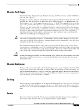
... is equipped with four DC-input power entry modules (PEMs). 78-16082-01 Cisco 12016, Cisco 12416, and Cisco 12816 Router Chassis Replacement Instructions 3 Caution All line card slots must be installed in the lower card cage is reserved for network data and system communication across the internal system maintenance bus (MBus). Nearly all times to accept...
... is equipped with four DC-input power entry modules (PEMs). 78-16082-01 Cisco 12016, Cisco 12416, and Cisco 12816 Router Chassis Replacement Instructions 3 Caution All line card slots must be installed in the lower card cage is reserved for network data and system communication across the internal system maintenance bus (MBus). Nearly all times to accept...
Chassis Replacement Instructions
Page 6
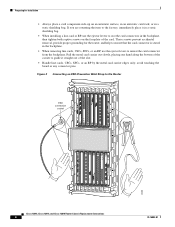
...bag. avoid touching the board or any connector pins. Pull the metal card carrier out slowly, placing one hand along the bottom of the slot. • Handle line cards, CSCs, SFCs, or an RP by the metal card carrier edges only; If you are returning the item to the factory,...TX RX RX 1 1 0 TX TX RX RX 0 0 TX TX CD CD LA LA CDHNT CDHNT RA RA DOWN LOOP DOWN LOOP 26208 Cisco 12016, Cisco 12416, and Cisco 12816 Router Chassis Replacement Instructions 6 78-16082-01 These screws prevent accidental removal, provide proper grounding for Installation • Always place...
...bag. avoid touching the board or any connector pins. Pull the metal card carrier out slowly, placing one hand along the bottom of the slot. • Handle line cards, CSCs, SFCs, or an RP by the metal card carrier edges only; If you are returning the item to the factory,...TX RX RX 1 1 0 TX TX RX RX 0 0 TX TX CD CD LA LA CDHNT CDHNT RA RA DOWN LOOP DOWN LOOP 26208 Cisco 12016, Cisco 12416, and Cisco 12816 Router Chassis Replacement Instructions 6 78-16082-01 These screws prevent accidental removal, provide proper grounding for Installation • Always place...
Chassis Replacement Instructions
Page 10
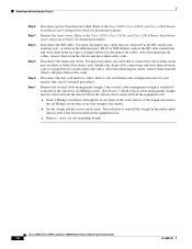
... remaining trough. Refer to the installation and configuration note for your specific line card for detailed procedures. After disconnecting the cables, remove them from the power shelf. Refer to the Cisco 12016, Cisco 12416, and Cisco 12816 Router Installation and Configuration Guide for detailed procedures. c. Cisco 12016, Cisco 12416, and Cisco 12816 Router Chassis Replacement Instructions 10 78-16082-01
... remaining trough. Refer to the installation and configuration note for your specific line card for detailed procedures. After disconnecting the cables, remove them from the power shelf. Refer to the Cisco 12016, Cisco 12416, and Cisco 12816 Router Installation and Configuration Guide for detailed procedures. c. Cisco 12016, Cisco 12416, and Cisco 12816 Router Chassis Replacement Instructions 10 78-16082-01
Chassis Replacement Instructions
Page 12
...configuration note for detailed procedures. • For line cards, refer to the line card installation and configuration note for detailed procedures. • For CSCs, SFCs, and the alarm card, refer to the Cisco 12016, Cisco 12416, and Cisco 12816 Router Installation and Configuration Guide for detailed... replacement chassis. Remove the cards from the Equipment Rack, page 13 Detaching the Supplemental Bonding and Grounding Connection If your router has supplemental bonding and grounding cables attached to the Cisco 12016, Cisco 12416, and Cisco 12816 Router Installation and Configuration...
...configuration note for detailed procedures. • For line cards, refer to the line card installation and configuration note for detailed procedures. • For CSCs, SFCs, and the alarm card, refer to the Cisco 12016, Cisco 12416, and Cisco 12816 Router Installation and Configuration Guide for detailed... replacement chassis. Remove the cards from the Equipment Rack, page 13 Detaching the Supplemental Bonding and Grounding Connection If your router has supplemental bonding and grounding cables attached to the Cisco 12016, Cisco 12416, and Cisco 12816 Router Installation and Configuration...
Chassis Replacement Instructions
Page 21
... rack-mounting flange near the upper horizontal cable-management tray. Reconnect the line card interface cables. Refer to the RP. Reconnect the cables to the Cisco 12016, Cisco 12416, and Cisco 12816 Router Power System Procedures Guide for detailed procedures. 78-16082-01 Cisco 12016, Cisco 12416, and Cisco 12816 Router Chassis Replacement Instructions 21 Insert a Phillips screwdriver through the...
... rack-mounting flange near the upper horizontal cable-management tray. Reconnect the line card interface cables. Refer to the RP. Reconnect the cables to the Cisco 12016, Cisco 12416, and Cisco 12816 Router Power System Procedures Guide for detailed procedures. 78-16082-01 Cisco 12016, Cisco 12416, and Cisco 12816 Router Chassis Replacement Instructions 21 Insert a Phillips screwdriver through the...
Chassis Replacement Instructions
Page 22
...slots, and all captive screws are tightened. • Line card cable-management brackets are attached to their respective line cards and all captive screws are tightened. • Interface cables are completely seated in their line card connectors. • Interface cables are routed neatly through ...and secured. • Power shelf cables are fully connected to the Cisco 12016, Cisco 12416, and Cisco 12816 Router Installation and Configuration Guide for detailed instructions. Cisco 12016, Cisco 12416, and Cisco 12816 Router Chassis Replacement Instructions 22 78-16082-01 Refer to both ...
...slots, and all captive screws are tightened. • Line card cable-management brackets are attached to their respective line cards and all captive screws are tightened. • Interface cables are completely seated in their line card connectors. • Interface cables are routed neatly through ...and secured. • Power shelf cables are fully connected to the Cisco 12016, Cisco 12416, and Cisco 12816 Router Installation and Configuration Guide for detailed instructions. Cisco 12016, Cisco 12416, and Cisco 12816 Router Chassis Replacement Instructions 22 78-16082-01 Refer to both ...


