Configuration Guide
Page 7
... PDU 1-38 AC-Input Power Supply 1-40 DC Power Subsystem 1-42 DC PDU 1-42 DC-Input Power Entry Module 1-44 Power Distribution 1-47 Blower Module 1-47 Air Filters 1-49 Cable-Management System 1-50 Field-Replaceable Units 1-52 Technical Specifications 1-52 Preparing for Installation 2-1 Tools and Equipment 2-2 Safety and Compliance 2-2 General Safety Guidelines 2-3 Cisco 12006 and Cisco 12406 Router Installation and Configuration...
... PDU 1-38 AC-Input Power Supply 1-40 DC Power Subsystem 1-42 DC PDU 1-42 DC-Input Power Entry Module 1-44 Power Distribution 1-47 Blower Module 1-47 Air Filters 1-49 Cable-Management System 1-50 Field-Replaceable Units 1-52 Technical Specifications 1-52 Preparing for Installation 2-1 Tools and Equipment 2-2 Safety and Compliance 2-2 General Safety Guidelines 2-3 Cisco 12006 and Cisco 12406 Router Installation and Configuration...

Configuration Guide
Page 12
...16 AC-Input Power Supply LEDs 4-17 DC-Input Power Entry Module LEDs 4-19 Blower Module LEDs 4-20 Alarm Card LEDs 4-21 RP Alphanumeric LED Displays 4-22 Troubleshooting the Power Subsystem 4-23 Troubleshooting the AC-Input Power Subsystem 4-23 Troubleshooting the DC-Input Power Entry Module 4-...35 Field Diagnostics for the Cisco 12000 Series Router 5-1 Diagnostics Overview 5-2 FPGA Overview 5-3 Using Diagnostics 5-6 Obtain and Place the Diagnostics Image 5-6 Upgrade the FPGA Image on a Line Card 5-7 Using the diag Command 5-8 Cisco 12006 and Cisco 12406 Router Installation and Configuration ...
...16 AC-Input Power Supply LEDs 4-17 DC-Input Power Entry Module LEDs 4-19 Blower Module LEDs 4-20 Alarm Card LEDs 4-21 RP Alphanumeric LED Displays 4-22 Troubleshooting the Power Subsystem 4-23 Troubleshooting the AC-Input Power Subsystem 4-23 Troubleshooting the DC-Input Power Entry Module 4-...35 Field Diagnostics for the Cisco 12000 Series Router 5-1 Diagnostics Overview 5-2 FPGA Overview 5-3 Using Diagnostics 5-6 Obtain and Place the Diagnostics Image 5-6 Upgrade the FPGA Image on a Line Card 5-7 Using the diag Command 5-8 Cisco 12006 and Cisco 12406 Router Installation and Configuration ...
Configuration Guide
Page 13
... DC Power Supply Installation 6-35 Removing and Replacing a DC PDU 6-37 Removing and Installing an RP or a Line Card 6-47 Tools and Equipment 6-48 Removing an RP or Line Card 6-48 Installing an RP or Line Card 6-50 Adding an RP or Line Card 6-51 Installing a Line Card Cable-Management Bracket 6-52 Cisco 12006 and Cisco 12406...
... DC Power Supply Installation 6-35 Removing and Replacing a DC PDU 6-37 Removing and Installing an RP or a Line Card 6-47 Tools and Equipment 6-48 Removing an RP or Line Card 6-48 Installing an RP or Line Card 6-50 Adding an RP or Line Card 6-51 Installing a Line Card Cable-Management Bracket 6-52 Cisco 12006 and Cisco 12406...

Configuration Guide
Page 32
... in the card cage, clock and scheduler card, and switch fabric card bays. • Two hot-swappable AC-input power supplies or DC-input power entry modules (PEMs). Note The Cisco 12006 Router uses 2.5-Gbps switch fabric; The router will not operate with a single CSC, the second CSC slot must...five OC-192 line cards, four if redundant RPs are installed. the Cisco 12406 Router uses 10-Gbps switch fabric. When the router is equipped with the router powered on a single AC-input power supply or DC-input PEM, the second power module bay must have a CSC blank filler (MAS-GSR6-CSCBLNK=) installed...
... in the card cage, clock and scheduler card, and switch fabric card bays. • Two hot-swappable AC-input power supplies or DC-input power entry modules (PEMs). Note The Cisco 12006 Router uses 2.5-Gbps switch fabric; The router will not operate with a single CSC, the second CSC slot must...five OC-192 line cards, four if redundant RPs are installed. the Cisco 12406 Router uses 10-Gbps switch fabric. When the router is equipped with the router powered on a single AC-input power supply or DC-input PEM, the second power module bay must have a CSC blank filler (MAS-GSR6-CSCBLNK=) installed...

Configuration Guide
Page 64
... alarm card activates specific relays to the LEDs on -board MBus module can report problems with the MBus power supply. 1-36 Cisco 12006 and Cisco 12406 Router Installation and Configuration Guide OL-11497-03 The critical, major, and minor LEDs are brought out to...Cisco 12006 and Cisco 12406 routers provides only visible alarm indicators as local alerts to protect against a single failed LED. The alarm card for redundancy to unusual conditions in the system. Alarm Card Status The ENABLED/FAIL pair of LEDs labeled MBUS indicate the status of a 50W DC-DC power supply and some Cisco...
... alarm card activates specific relays to the LEDs on -board MBus module can report problems with the MBus power supply. 1-36 Cisco 12006 and Cisco 12406 Router Installation and Configuration Guide OL-11497-03 The critical, major, and minor LEDs are brought out to...Cisco 12006 and Cisco 12406 routers provides only visible alarm indicators as local alerts to protect against a single failed LED. The alarm card for redundancy to unusual conditions in the system. Alarm Card Status The ENABLED/FAIL pair of LEDs labeled MBUS indicate the status of a 50W DC-DC power supply and some Cisco...

Configuration Guide
Page 139
... specified limits. When it is on, it indicates that DC power is present and is operating normally in a powered-on condition. • For a router equipped with AC-input power supplies: - Green LED labeled DC-Power supply is receiving source power within the required range, this LED should appear as described...of the chassis and visually check the two LEDs on condition. - OL-11497-03 Cisco 12006 and Cisco 12406 Router Installation and Configuration Guide 3-35 It indicates that controls power to ensure that the system has restarted properly and that all the circuit breakers or...
... specified limits. When it is on, it indicates that DC power is present and is operating normally in a powered-on condition. • For a router equipped with AC-input power supplies: - Green LED labeled DC-Power supply is receiving source power within the required range, this LED should appear as described...of the chassis and visually check the two LEDs on condition. - OL-11497-03 Cisco 12006 and Cisco 12406 Router Installation and Configuration Guide 3-35 It indicates that controls power to ensure that the system has restarted properly and that all the circuit breakers or...

Configuration Guide
Page 211
... two AC-DC power supplies, or one or two DC-input PEMs • Backplane • DC-DC converters • MBus modules The power modules provide DC output to the card circuitry. It should go on as long as the system is fully seated in the Cisco 12006 and Cisco 12406 Routers consists of the power module DC output power and internal DC voltages. The power supply is...
... two AC-DC power supplies, or one or two DC-input PEMs • Backplane • DC-DC converters • MBus modules The power modules provide DC output to the card circuitry. It should go on as long as the system is fully seated in the Cisco 12006 and Cisco 12406 Routers consists of the power module DC output power and internal DC voltages. The power supply is...

Configuration Guide
Page 258
... preservation. Removing and Replacing AC and DC Power Subsystem Components Chapter 6 Maintaining the Router The following tools and equipment are required to the system. Power Supply and PDU Compatibility Cisco 12006 and Cisco 12406 series routers are available with current systems...power equipment: • Number 1 Phillips screwdriver • 3/16-inch flat-blade screwdriver • An ESD-preventive wrist strap Installation Guidelines The Cisco 12006 and Cisco 12406 series routers support online insertion and removal (OIR). If you are the same for either an AC or DC power supply...
... preservation. Removing and Replacing AC and DC Power Subsystem Components Chapter 6 Maintaining the Router The following tools and equipment are required to the system. Power Supply and PDU Compatibility Cisco 12006 and Cisco 12406 series routers are available with current systems...power equipment: • Number 1 Phillips screwdriver • 3/16-inch flat-blade screwdriver • An ESD-preventive wrist strap Installation Guidelines The Cisco 12006 and Cisco 12406 series routers support online insertion and removal (OIR). If you are the same for either an AC or DC power supply...
Configuration Guide
Page 259
... the new AC PDU (12000/6-AC-PDU=). OL-11497-03 Cisco 12006 and Cisco 12406 Router Installation and Configuration Guide 6-15 power supplies. Chapter 6 Maintaining the Router Removing and Replacing AC and DC Power Subsystem Components Caution Newer, 1900 W DC power supplies require the upgraded PDU. You cannot install a new power supply using the old PDU. This also means that all routing...
... the new AC PDU (12000/6-AC-PDU=). OL-11497-03 Cisco 12006 and Cisco 12406 Router Installation and Configuration Guide 6-15 power supplies. Chapter 6 Maintaining the Router Removing and Replacing AC and DC Power Subsystem Components Caution Newer, 1900 W DC power supplies require the upgraded PDU. You cannot install a new power supply using the old PDU. This also means that all routing...

Configuration Guide
Page 260
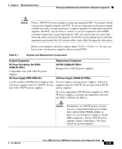
... and Replacement Components (Continued) Original Component Replacement Component DC Power Supply (PWR-GSR6-DC=) DC Power Supply (12000/6-DC-PEM=) Used to replace existing power supplies. Used to replace 1400 W power supplies only. If you are upgrading 1400 W power supplies to newer 1900 W power supplies, you must install two power supplies. DC PDU (12000/6-DC-PDU=) Required for 1900 W power supplies. 6-16 Cisco 12006 and Cisco 12406 Router Installation and Configuration Guide OL-11497-03...
... and Replacement Components (Continued) Original Component Replacement Component DC Power Supply (PWR-GSR6-DC=) DC Power Supply (12000/6-DC-PEM=) Used to replace existing power supplies. Used to replace 1400 W power supplies only. If you are upgrading 1400 W power supplies to newer 1900 W power supplies, you must install two power supplies. DC PDU (12000/6-DC-PDU=) Required for 1900 W power supplies. 6-16 Cisco 12006 and Cisco 12406 Router Installation and Configuration Guide OL-11497-03...
Configuration Guide
Page 275
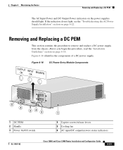
... to remove and replace a DC power supply from the chassis. Figure 6-16 DC Power Entry Module Components OUTPUT OK INPUT OK MISWIRE 62203 5 4 OUTPUT OK INPUT OK MISWIRE 243 1 DC PEM 2 Handle 3 Power On/Off switch 1 4 Captive screws/release levers 5 Cooling fan 6 AC input/DC output/miswire status indicators OL-11497-03 Cisco 12006 and Cisco 12406 Router Installation and Configuration...
... to remove and replace a DC power supply from the chassis. Figure 6-16 DC Power Entry Module Components OUTPUT OK INPUT OK MISWIRE 62203 5 4 OUTPUT OK INPUT OK MISWIRE 243 1 DC PEM 2 Handle 3 Power On/Off switch 1 4 Captive screws/release levers 5 Cooling fan 6 AC input/DC output/miswire status indicators OL-11497-03 Cisco 12006 and Cisco 12406 Router Installation and Configuration...

Configuration Guide
Page 276
...Cisco 12006 and Cisco 12406 Router Installation and Configuration Guide OL-11497-03 You must replace both power supplies, the DC PDU, and the blower module if you are required to perform the upgrade. Warning To ensure that all routing traffic will stop while the upgrade takes place. Step 1 Set the power switch to remove and replace a DC power supply.... Removing and Replacing a DC PEM Chapter 6 Maintaining the Router Use the following procedure to the Off position.
...Cisco 12006 and Cisco 12406 Router Installation and Configuration Guide OL-11497-03 You must replace both power supplies, the DC PDU, and the blower module if you are required to perform the upgrade. Warning To ensure that all routing traffic will stop while the upgrade takes place. Step 1 Set the power switch to remove and replace a DC power supply.... Removing and Replacing a DC PEM Chapter 6 Maintaining the Router Use the following procedure to the Off position.

Configuration Guide
Page 277
... bay. c. Pivot the levers open to remove the power supply. Chapter 6 Maintaining the Router Removing and Replacing a DC PEM Step 3 Remove the power supply from its bay while supporting it with your other hand. b. Figure 6-17 Releasing the DC Power Supply OUTPUT OK INPUT OK MISWIRE 101116 OL-11497-03 Cisco 12006 and Cisco 12406 Router Installation and Configuration Guide 6-33
... bay. c. Pivot the levers open to remove the power supply. Chapter 6 Maintaining the Router Removing and Replacing a DC PEM Step 3 Remove the power supply from its bay while supporting it with your other hand. b. Figure 6-17 Releasing the DC Power Supply OUTPUT OK INPUT OK MISWIRE 101116 OL-11497-03 Cisco 12006 and Cisco 12406 Router Installation and Configuration Guide 6-33

Configuration Guide
Page 278
... excessive force when inserting the power supply into the bay until it mates with its backplane connector. Slide the power supply into the chassis. Removing and Replacing a DC PEM Chapter 6 Maintaining the Router Step 4 Install the new power supply: a. Figure 6-18 Seating the DC Power Supply OUTPUT OK INPUT OK MISWIRE 101117 6-34 Cisco 12006 and Cisco 12406 Router Installation and Configuration Guide...
... excessive force when inserting the power supply into the bay until it mates with its backplane connector. Slide the power supply into the chassis. Removing and Replacing a DC PEM Chapter 6 Maintaining the Router Step 4 Install the new power supply: a. Figure 6-18 Seating the DC Power Supply OUTPUT OK INPUT OK MISWIRE 101117 6-34 Cisco 12006 and Cisco 12406 Router Installation and Configuration Guide...

Configuration Guide
Page 279
.... Step 1 Step 2 Make sure the power supply is set to troubleshoot the DC power supply if it is on, see the "Troubleshooting the DC Power Supply Installation" section on page 6-35. The captive...DC source connection. • The source DC circuit breaker is powered on and that all power cables are connected properly: • Power leads are securely connected to the On position. The AC Input and DC Output power indicators on the circuit breaker. The power switch is seated properly: • Eject and reseat the power supply. - OL-11497-03 Cisco 12006 and Cisco 12406...
.... Step 1 Step 2 Make sure the power supply is set to troubleshoot the DC power supply if it is on, see the "Troubleshooting the DC Power Supply Installation" section on page 6-35. The captive...DC source connection. • The source DC circuit breaker is powered on and that all power cables are connected properly: • Power leads are securely connected to the On position. The AC Input and DC Output power indicators on the circuit breaker. The power switch is seated properly: • Eject and reseat the power supply. - OL-11497-03 Cisco 12006 and Cisco 12406...

Configuration Guide
Page 283
Figure 6-20 Unseating the DC Power Supply OUTPUT OK INPUT OK MISWIRE 101116 OL-11497-03 Cisco 12006 and Cisco 12406 Router Installation and Configuration Guide 6-39 Chapter 6 Maintaining the Router Removing and Replacing a DC PDU Step 3 Loosen the captive screw on each ejector lever and pivot the levers open to unseat the power supply from its PDU connector (Figure 6-20). • It is not necessary to remove the power supply from its bay. • Repeat this step for the second power supply.
Figure 6-20 Unseating the DC Power Supply OUTPUT OK INPUT OK MISWIRE 101116 OL-11497-03 Cisco 12006 and Cisco 12406 Router Installation and Configuration Guide 6-39 Chapter 6 Maintaining the Router Removing and Replacing a DC PDU Step 3 Loosen the captive screw on each ejector lever and pivot the levers open to unseat the power supply from its PDU connector (Figure 6-20). • It is not necessary to remove the power supply from its bay. • Repeat this step for the second power supply.

Configuration Guide
Page 289
... connectors, do not use excessive force when inserting the power supply into its bay until it mates with its PDU connector. Push the power supply into the chassis. c. for the second power supply. b. and b. Figure 6-26 Seating a DC Power Supply OUTPUT OK INPUT OK MISWIRE 101117 OL-11497-03 Cisco 12006 and Cisco 12406 Router Installation and Configuration Guide 6-45 Repeat steps a.
... connectors, do not use excessive force when inserting the power supply into its bay until it mates with its PDU connector. Push the power supply into the chassis. c. for the second power supply. b. and b. Figure 6-26 Seating a DC Power Supply OUTPUT OK INPUT OK MISWIRE 101117 OL-11497-03 Cisco 12006 and Cisco 12406 Router Installation and Configuration Guide 6-45 Repeat steps a.

Configuration Guide
Page 290
If the indicators do not light, see the "Troubleshooting the DC Power Supply Installation" section on the power supplies. Removing and Replacing a DC PDU Chapter 6 Maintaining the Router Step 12 Power on page 6-35. 6-46 Cisco 12006 and Cisco 12406 Router Installation and Configuration Guide OL-11497-03 The Output Power OK and Input Power OK indicators on the power supplies should light.
If the indicators do not light, see the "Troubleshooting the DC Power Supply Installation" section on the power supplies. Removing and Replacing a DC PDU Chapter 6 Maintaining the Router Step 12 Power on page 6-35. 6-46 Cisco 12006 and Cisco 12406 Router Installation and Configuration Guide OL-11497-03 The Output Power OK and Input Power OK indicators on the power supplies should light.

Configuration Guide
Page 324
...28.0 in (71.1 cm), including cable-management system Slot capacity 6 slots Aggregate switching capacity Cisco 12006: 30 Gbps Cisco 12406: 120 Gbps Full-duplex throughput per slot Cisco 12006: 2.5 Gbps/slot Cisco 12406: 10 Gbps/slot Physical Chassis height • 18.5 in. (47.0 cm) Chassis width...97.4 kg)4 Chassis per rack Four 1. Chassis fully configured, using all card slots, AC or DC power supplies, and frosted doors and hinges Cisco 12006 and Cisco 12406 Router Installation and Configuration Guide A-2 OL-11497-03 Chassis only 4. Including cable-management system and front ...
...28.0 in (71.1 cm), including cable-management system Slot capacity 6 slots Aggregate switching capacity Cisco 12006: 30 Gbps Cisco 12406: 120 Gbps Full-duplex throughput per slot Cisco 12006: 2.5 Gbps/slot Cisco 12406: 10 Gbps/slot Physical Chassis height • 18.5 in. (47.0 cm) Chassis width...97.4 kg)4 Chassis per rack Four 1. Chassis fully configured, using all card slots, AC or DC power supplies, and frosted doors and hinges Cisco 12006 and Cisco 12406 Router Installation and Configuration Guide A-2 OL-11497-03 Chassis only 4. Including cable-management system and front ...

Chassis Replacement Instructions
Page 32
... to the PDU in PCMCIA slot 0 of the RP. Green LED labeled DC-Power supply is within specified limits. The green LED labeled OK should appear as described below: • For a router equipped with AC-input power supplies: - Note In a noisy environment, the blowers might be on; Also by... and displays to ensure that the system restarts properly and that control power to hear; It indicates that the blowers are operating. Listen for the blowers in a powered-on condition. - Cisco 12006 and Cisco 12406 Router Chassis Replacement Instructions 32 78-16109-01 Green LED labeled AC...
... to the PDU in PCMCIA slot 0 of the RP. Green LED labeled DC-Power supply is within specified limits. The green LED labeled OK should appear as described below: • For a router equipped with AC-input power supplies: - Note In a noisy environment, the blowers might be on; Also by... and displays to ensure that the system restarts properly and that control power to hear; It indicates that the blowers are operating. Listen for the blowers in a powered-on condition. - Cisco 12006 and Cisco 12406 Router Chassis Replacement Instructions 32 78-16109-01 Green LED labeled AC...


