Configuration Guide
Page 7
... DC Power Subsystem 1-42 DC PDU 1-42 DC-Input Power Entry Module 1-44 Power Distribution 1-47 Blower Module 1-47 Air Filters 1-49 Cable-Management System 1-50 Field-Replaceable Units 1-52 Technical Specifications 1-52 Preparing for Installation 2-1 Tools and Equipment 2-2 Safety and Compliance 2-2 General Safety Guidelines 2-3 Cisco 12006 and Cisco 12406 Router Installation and Configuration Guide 5
... DC Power Subsystem 1-42 DC PDU 1-42 DC-Input Power Entry Module 1-44 Power Distribution 1-47 Blower Module 1-47 Air Filters 1-49 Cable-Management System 1-50 Field-Replaceable Units 1-52 Technical Specifications 1-52 Preparing for Installation 2-1 Tools and Equipment 2-2 Safety and Compliance 2-2 General Safety Guidelines 2-3 Cisco 12006 and Cisco 12406 Router Installation and Configuration Guide 5
Configuration Guide
Page 13
...diag Command Reference 5-9 Output Examples 5-14 Maintaining the Router 6-1 Powering Down the Router 6-2 Removing and Installing the Front Door on Cisco 12006 and Cisco 12406 Enhanced Series Router 6-3 Cleaning or Replacing the Air Filters 6-7 Removing and Replacing the Blower Module 6-9 Troubleshooting the Blower Installation 6-12 Removing and Replacing AC and DC Power Subsystem Components 6-... Card 6-48 Installing an RP or Line Card 6-50 Adding an RP or Line Card 6-51 Installing a Line Card Cable-Management Bracket 6-52 Cisco 12006 and Cisco 12406 Router Installation and Configuration Guide 11
...diag Command Reference 5-9 Output Examples 5-14 Maintaining the Router 6-1 Powering Down the Router 6-2 Removing and Installing the Front Door on Cisco 12006 and Cisco 12406 Enhanced Series Router 6-3 Cleaning or Replacing the Air Filters 6-7 Removing and Replacing the Blower Module 6-9 Troubleshooting the Blower Installation 6-12 Removing and Replacing AC and DC Power Subsystem Components 6-... Card 6-48 Installing an RP or Line Card 6-50 Adding an RP or Line Card 6-51 Installing a Line Card Cable-Management Bracket 6-52 Cisco 12006 and Cisco 12406 Router Installation and Configuration Guide 11

Configuration Guide
Page 35
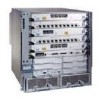
...For more information about the role of the router to five line cards. OL-11497-03 Cisco 12006 and Cisco 12406 Router Installation and Configuration Guide 1-7 Note Cisco 12006 and Cisco 12406 routers use line cards that connect the switch fabric of the line cards, see Figure 1-1.)..., page 1-35 • Power Subsystems, page 1-37 • Blower Module, page 1-47 • Air Filters, page 1-49 • Cable-Management System, page 1-50 Chassis The Cisco 12006 and Cisco 12406 router chassis is an enclosure that consists of the RP, see the "Route Processors" section on page 1-33...
...For more information about the role of the router to five line cards. OL-11497-03 Cisco 12006 and Cisco 12406 Router Installation and Configuration Guide 1-7 Note Cisco 12006 and Cisco 12406 routers use line cards that connect the switch fabric of the line cards, see Figure 1-1.)..., page 1-35 • Power Subsystems, page 1-37 • Blower Module, page 1-47 • Air Filters, page 1-49 • Cable-Management System, page 1-50 Chassis The Cisco 12006 and Cisco 12406 router chassis is an enclosure that consists of the RP, see the "Route Processors" section on page 1-33...

Configuration Guide
Page 75
...configuration complies with a blower module to distribute air within the chassis. Failure to properly verify the configuration may cause overheating. Blower Module Cisco 12006 and Cisco 12406 routers are turned on the back of the chassis, pulls the air through the chassis card cages, and expels .... (See Figure 1-2.) The blower module draws room air into the chassis through two air filters on -line power calculator. The front, back, and sides of the RP and MBus software. OL-11497-03 Cisco 12006 and Cisco 12406 Router Installation and Configuration Guide 1-47 Chapter 1 Product...
...configuration complies with a blower module to distribute air within the chassis. Failure to properly verify the configuration may cause overheating. Blower Module Cisco 12006 and Cisco 12406 routers are turned on the back of the chassis, pulls the air through the chassis card cages, and expels .... (See Figure 1-2.) The blower module draws room air into the chassis through two air filters on -line power calculator. The front, back, and sides of the RP and MBus software. OL-11497-03 Cisco 12006 and Cisco 12406 Router Installation and Configuration Guide 1-47 Chapter 1 Product...

Configuration Guide
Page 76
... Air Flow (Top View) Air exhaust Air exhaust Blower module Room air Room air 57649 Top view Air filter The two LEDs on the console screen. If the system detects that one of three fans within a blower module has failed, it displays a warning message on the blower module provide a visual indication of the chassis. 1-48 Cisco 12006 and Cisco 12406...
... Air Flow (Top View) Air exhaust Air exhaust Blower module Room air Room air 57649 Top view Air filter The two LEDs on the console screen. If the system detects that one of three fans within a blower module has failed, it displays a warning message on the blower module provide a visual indication of the chassis. 1-48 Cisco 12006 and Cisco 12406...

Configuration Guide
Page 77
... RESET AUX CONSOLE COLL RX LINK TX RJ-45 MII GIGABIT ROUTE PROCESSOR 57678 OL-11497-03 Cisco 12006 and Cisco 12406 Router Installation and Configuration Guide 1-49 Green. This LED should remain off during normal operation. Air Filters Cisco 12006 and Cisco 12406 routers are equipped with a spare. Chapter 1 Product Overview Blower Module • OK-Left LED...
... RESET AUX CONSOLE COLL RX LINK TX RJ-45 MII GIGABIT ROUTE PROCESSOR 57678 OL-11497-03 Cisco 12006 and Cisco 12406 Router Installation and Configuration Guide 1-49 Green. This LED should remain off during normal operation. Air Filters Cisco 12006 and Cisco 12406 routers are equipped with a spare. Chapter 1 Product Overview Blower Module • OK-Left LED...

Configuration Guide
Page 78
... ties on the line card. 1-50 Cisco 12006 and Cisco 12406 Router Installation and Configuration Guide OL-11497-03 You should be clean when the router is installed on the right of the front side of the chassis is spring-loaded in the "Cleaning or Replacing the Air Filters" section on page 6-7. Cable-Management System...
... ties on the line card. 1-50 Cisco 12006 and Cisco 12406 Router Installation and Configuration Guide OL-11497-03 You should be clean when the router is installed on the right of the front side of the chassis is spring-loaded in the "Cleaning or Replacing the Air Filters" section on page 6-7. Cable-Management System...

Configuration Guide
Page 80
...-powered systems, DC-input PEMs • AC power cords (for AC powered systems) • Blower module • Air filters • Chassis cable-management bracket Technical Specifications For technical specifications and compliance information for Cisco 12006 and Cisco 12406 routers include the following units: • Route processor • Line cards • CSCs • SFCs • Alarm...
...-powered systems, DC-input PEMs • AC power cords (for AC powered systems) • Blower module • Air filters • Chassis cable-management bracket Technical Specifications For technical specifications and compliance information for Cisco 12006 and Cisco 12406 routers include the following units: • Route processor • Line cards • CSCs • SFCs • Alarm...

Configuration Guide
Page 89
.... Observe the following environmental considerations are discussed: • Airflow • Temperature and humidity Airflow The air circulation system for operating Cisco 12006 and Cisco 12406 Routers in which to install Cisco 12006 and Cisco 12406 Routers: OL-11497-03 Cisco 12006 and Cisco 12406 Router Installation and Configuration Guide 2-9 Air circulates through replaceable air filters located on the right side of the chassis.
.... Observe the following environmental considerations are discussed: • Airflow • Temperature and humidity Airflow The air circulation system for operating Cisco 12006 and Cisco 12406 Routers in which to install Cisco 12006 and Cisco 12406 Routers: OL-11497-03 Cisco 12006 and Cisco 12406 Router Installation and Configuration Guide 2-9 Air circulates through replaceable air filters located on the right side of the chassis.

Configuration Guide
Page 90
... operate. The environmental monitoring functionality built into Cisco 12006 and Cisco 12406 Routers protects the system and components from potential damage from overvoltage and overtemperature conditions. If the air flow is blocked or restricted, or if the inlet air is too warm, an overtemperature condition can clog the air filter or power supply intake vents, reducing the...
... operate. The environmental monitoring functionality built into Cisco 12006 and Cisco 12406 Routers protects the system and components from potential damage from overvoltage and overtemperature conditions. If the air flow is blocked or restricted, or if the inlet air is too warm, an overtemperature condition can clog the air filter or power supply intake vents, reducing the...

Configuration Guide
Page 93
... powerful in cooling the router. OL-11497-03 Cisco 12006 and Cisco 12406 Router Installation and Configuration Guide 2-13 Note Warm air is mounted at both the inlet and exhaust openings on the chassis to allow sufficient air flow. • When placing multiple Cisco 12006 and Cisco 12406 Routers in the same rack, ensure that there... from other equipment do not impair access to the card cages, requiring you to disconnect cables unnecessarily to the air filters and blower module should not be blocked. If necessary, operate the router with the rack door open or in an open rack. •...
... powerful in cooling the router. OL-11497-03 Cisco 12006 and Cisco 12406 Router Installation and Configuration Guide 2-13 Note Warm air is mounted at both the inlet and exhaust openings on the chassis to allow sufficient air flow. • When placing multiple Cisco 12006 and Cisco 12406 Routers in the same rack, ensure that there... from other equipment do not impair access to the card cages, requiring you to disconnect cables unnecessarily to the air filters and blower module should not be blocked. If necessary, operate the router with the rack door open or in an open rack. •...

Configuration Guide
Page 106
...checked for compatibility with your site is suitable for the router. • AC power source receptacles are not blocked. • The air filter is mounted on the right side as you can read the blower module LEDs and perform maintenance on the module. • There ... page 3-5 • Installing the Chassis on a Tabletop or Flat Surface, page 3-9 Before installing Cisco 12006 and Cisco 12406 Routers, see Chapter 2, "Preparing for Installation," for information on environmental considerations and requirements. air flow to the blower module is not blocked. • There is 24 inches (61 cm) of...
...checked for compatibility with your site is suitable for the router. • AC power source receptacles are not blocked. • The air filter is mounted on the right side as you can read the blower module LEDs and perform maintenance on the module. • There ... page 3-5 • Installing the Chassis on a Tabletop or Flat Surface, page 3-9 Before installing Cisco 12006 and Cisco 12406 Routers, see Chapter 2, "Preparing for Installation," for information on environmental considerations and requirements. air flow to the blower module is not blocked. • There is 24 inches (61 cm) of...

Configuration Guide
Page 110
..., then insert a screw in the bracket and finger tighten that the bracket does not impede airflow through the air filter, which could cause overheating in the lower bracket with the marked screw hole. Cisco 12006 and Cisco 12406 Router Installation and Configuration Guide 3-6 OL-11497-03 Repeat Step 2a through Step 5 for both the left...
..., then insert a screw in the bracket and finger tighten that the bracket does not impede airflow through the air filter, which could cause overheating in the lower bracket with the marked screw hole. Cisco 12006 and Cisco 12406 Router Installation and Configuration Guide 3-6 OL-11497-03 Repeat Step 2a through Step 5 for both the left...

Configuration Guide
Page 224
...Cisco 12006 and Cisco 12406 Router Installation and Configuration Guide OL-11497-03 If the blower module is faulty, you are still unable to the "Troubleshooting the Power Subsystem" section on page 4-23." • Although overheating is unlikely at initial startup, be sure that heated exhaust air...Solving with Subsystems Chapter 4 Troubleshooting the Installation • The following console monitor message indicates that there is not entering the air filter, and that the system has detected an overtemperature or out-of-tolerance power condition in slots on before the system shuts ...
...Cisco 12006 and Cisco 12406 Router Installation and Configuration Guide OL-11497-03 If the blower module is faulty, you are still unable to the "Troubleshooting the Power Subsystem" section on page 4-23." • Although overheating is unlikely at initial startup, be sure that heated exhaust air...Solving with Subsystems Chapter 4 Troubleshooting the Installation • The following console monitor message indicates that there is not entering the air filter, and that the system has detected an overtemperature or out-of-tolerance power condition in slots on before the system shuts ...

Configuration Guide
Page 245
... following maintenance procedures: • Powering Down the Router, page 6-2 • Removing and Installing the Front Door on Cisco 12006 and Cisco 12406 Enhanced Series Router, page 6-3 • Cleaning or Replacing the Air Filters, page 6-7 • Cleaning or Replacing the Air Filters, page 6-7 • Removing and Replacing the Blower Module, page 6-9 • Removing and Replacing AC and DC...
... following maintenance procedures: • Powering Down the Router, page 6-2 • Removing and Installing the Front Door on Cisco 12006 and Cisco 12406 Enhanced Series Router, page 6-3 • Cleaning or Replacing the Air Filters, page 6-7 • Cleaning or Replacing the Air Filters, page 6-7 • Removing and Replacing the Blower Module, page 6-9 • Removing and Replacing AC and DC...

Configuration Guide
Page 251
... (see Figure 6-2). c. Close the front door by the blower module. Cleaning or Replacing the Air Filters The Cisco 12006 and Cisco 12406 routers are equipped with two user-serviceable air filters that remove dust drawn into the router by pressing the latch button allowing the door latch to ...hinge pins to the chassis: a. OL-11497-03 Cisco 12006 and Cisco 12406 Router Installation and Configuration Guide 6-7 b. Remove the hinge pins from the hinges on the chassis. Chapter 6 Maintaining the Router Cleaning or Replacing the Air Filters Step 6 Attach the front door to hold the ...
... (see Figure 6-2). c. Close the front door by the blower module. Cleaning or Replacing the Air Filters The Cisco 12006 and Cisco 12406 routers are equipped with two user-serviceable air filters that remove dust drawn into the router by pressing the latch button allowing the door latch to ...hinge pins to the chassis: a. OL-11497-03 Cisco 12006 and Cisco 12406 Router Installation and Configuration Guide 6-7 b. Remove the hinge pins from the hinges on the chassis. Chapter 6 Maintaining the Router Cleaning or Replacing the Air Filters Step 6 Attach the front door to hold the ...

Configuration Guide
Page 252
... 129403 1 Air filter door 2 Air filters Cisco 12006 and Cisco 12406 Router Installation and Configuration Guide 6-8 OL-11497-03 Step 1 Open the spring-loaded air filter door on the right side of the chassis and remove an air filter by pulling the small tab on the edge of the filter (Figure 6-4). Remove the second air filter the same way. Cleaning or Replacing the Air Filters Chapter...
... 129403 1 Air filter door 2 Air filters Cisco 12006 and Cisco 12406 Router Installation and Configuration Guide 6-8 OL-11497-03 Step 1 Open the spring-loaded air filter door on the right side of the chassis and remove an air filter by pulling the small tab on the edge of the filter (Figure 6-4). Remove the second air filter the same way. Cleaning or Replacing the Air Filters Chapter...

Configuration Guide
Page 253
...the chassis. OL-11497-03 Cisco 12006 and Cisco 12406 Router Installation and Configuration Guide 6-9 Always install the air filter with original systems, and enhanced capacity blowers that indicates the direction of air flow. Caution Do not try to vacuum the air filter while it to prevent contaminants ... and line card cage. Note An arrow located on the edge of each air filter frame that ship with Cisco 12006 and Cisco 12406 series routers, airflow capacity for the Cisco 12006 and Cisco 12406 series routers; Note Compared to the original blower modules that shipped with current ...
...the chassis. OL-11497-03 Cisco 12006 and Cisco 12406 Router Installation and Configuration Guide 6-9 Always install the air filter with original systems, and enhanced capacity blowers that indicates the direction of air flow. Caution Do not try to vacuum the air filter while it to prevent contaminants ... and line card cage. Note An arrow located on the edge of each air filter frame that ship with Cisco 12006 and Cisco 12406 series routers, airflow capacity for the Cisco 12006 and Cisco 12406 series routers; Note Compared to the original blower modules that shipped with current ...

Configuration Guide
Page 312
...the following sections. Removing and Installing the Chassis Chapter 6 Maintaining the Router Removing and Installing the Chassis Instructions for removing a defective Cisco 12006 or Cisco 12406 Router chassis and installing a replacement chassis are presented in the following items to replace a router chassis: • ESD-preventive strap...clock and scheduler card cage • Three-slot switch fabric card cage • Two alarm card slots • Two air filters • Two power module bays • One backplane with connectors The chassis can be rack mounted or placed on a stable flat ...
...the following sections. Removing and Installing the Chassis Chapter 6 Maintaining the Router Removing and Installing the Chassis Instructions for removing a defective Cisco 12006 or Cisco 12406 Router chassis and installing a replacement chassis are presented in the following items to replace a router chassis: • ESD-preventive strap...clock and scheduler card cage • Three-slot switch fabric card cage • Two alarm card slots • Two air filters • Two power module bays • One backplane with connectors The chassis can be rack mounted or placed on a stable flat ...

Configuration Guide
Page 313
... alarm cards-from its shipping packaging and placed temporarily within reach of the rack in the replacement chassis. OL-11497-03 Cisco 12006 and Cisco 12406 Router Installation and Configuration Guide 6-69 Transferring components from the defective chassis and reinstall them temporarily outside their card cages, bays...procedures are transferred from the defective chassis to the replacement chassis. • The replacement chassis (and all the components except the air filter from one chassis to the other also helps to ensure that it ) is inserted into the same equipment rack or on a ...
... alarm cards-from its shipping packaging and placed temporarily within reach of the rack in the replacement chassis. OL-11497-03 Cisco 12006 and Cisco 12406 Router Installation and Configuration Guide 6-69 Transferring components from the defective chassis and reinstall them temporarily outside their card cages, bays...procedures are transferred from the defective chassis to the replacement chassis. • The replacement chassis (and all the components except the air filter from one chassis to the other also helps to ensure that it ) is inserted into the same equipment rack or on a ...
