
B550 B552 B750 Owner s Manual - English
Page 1
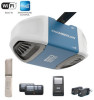
...Manual B550 • B552 • B750 Belt Drive Garage Door Opener FOR RESIDENTIAL USE ONLY PRE-PROGRAMMED REMOTE CONTROL INCLUDED Smart Garage Opener • Please read this manual and the enclosed safety materials carefully! • Fasten the manual near the garage door after installation.... 40 Troubleshooting 41-42 Accessories 43 Warranty 44 Repair Parts 45-47 www.chamberlain.com www.mychamberlain.com Contents Preparation 2-5 Assembly 6-10 Installation 11-28 Install the Door Control 21-22 Install the Protector System® .... 23-26 Connect power 27-28 Adjustments 29...
...Manual B550 • B552 • B750 Belt Drive Garage Door Opener FOR RESIDENTIAL USE ONLY PRE-PROGRAMMED REMOTE CONTROL INCLUDED Smart Garage Opener • Please read this manual and the enclosed safety materials carefully! • Fasten the manual near the garage door after installation.... 40 Troubleshooting 41-42 Accessories 43 Warranty 44 Repair Parts 45-47 www.chamberlain.com www.mychamberlain.com Contents Preparation 2-5 Assembly 6-10 Installation 11-28 Install the Door Control 21-22 Install the Protector System® .... 23-26 Connect power 27-28 Adjustments 29...

B550 B552 B750 Owner s Manual - English
Page 2
...with the warnings that allows the door to close . l Disable ALL locks and remove ALL ropes connected to garage door BEFORE installation and operating garage door opener to avoid malfunction and damage. Otherwise, the safety reversal system may NOT reverse when required. l ... Preparation Safety Symbol and Signal Word Review This garage door opener has been designed and tested to offer safe service provided it is installed, operated, maintained and tested in strict accordance with the instructions and warnings contained in place, supported entirely by its springs. 3. ...
...with the warnings that allows the door to close . l Disable ALL locks and remove ALL ropes connected to garage door BEFORE installation and operating garage door opener to avoid malfunction and damage. Otherwise, the safety reversal system may NOT reverse when required. l ... Preparation Safety Symbol and Signal Word Review This garage door opener has been designed and tested to offer safe service provided it is installed, operated, maintained and tested in strict accordance with the instructions and warnings contained in place, supported entirely by its springs. 3. ...

B550 B552 B750 Owner s Manual - English
Page 3
... signal is weak. Check Signal Strength. You're all set! l Support bracket and fastening hardware: Must be needed to position the garage door opener during installation and for more than 7 feet (2.13 m) high. 5/32 3/16 5/16 1/2 5/8 1/4 7/16 9/16 7/16 3 Wi-Fi signal is strong. l ...: Alternate floor mounting of the options below. No Wi-Fi signal. Try one of the safety reversing sensor will be used to install the safety reversing sensor. l Rail extension kit: Required if your garage door from walls and other mobile device. Preparation Before You Connect...
... signal is weak. Check Signal Strength. You're all set! l Support bracket and fastening hardware: Must be needed to position the garage door opener during installation and for more than 7 feet (2.13 m) high. 5/32 3/16 5/16 1/2 5/8 1/4 7/16 9/16 7/16 3 Wi-Fi signal is strong. l ...: Alternate floor mounting of the options below. No Wi-Fi signal. Try one of the safety reversing sensor will be used to install the safety reversing sensor. l Rail extension kit: Required if your garage door from walls and other mobile device. Preparation Before You Connect...
B550 B552 B750 Owner s Manual - English
Page 4
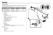
... rail section) J. G. Belt N. Curved door arm E. "U" bracket M. Emergency release rope and handle H. Door control O. The images throughout this manual. Model Power B550 Med Lift Power System™ B552 Med Lift Power System™ B750 Plus Lift Power System™ Door Control Multi-Function Multi-Function Motion Detecting...be attached to assemble the trolley before sliding onto rail. Preparation Carton Inventory Save the carton and packing material until the installation and adjustment is complete. Hanging brackets (2) (Packaged inside front rail section) F.
... rail section) J. G. Belt N. Curved door arm E. "U" bracket M. Emergency release rope and handle H. Door control O. The images throughout this manual. Model Power B550 Med Lift Power System™ B552 Med Lift Power System™ B750 Plus Lift Power System™ Door Control Multi-Function Multi-Function Motion Detecting...be attached to assemble the trolley before sliding onto rail. Preparation Carton Inventory Save the carton and packing material until the installation and adjustment is complete. Hanging brackets (2) (Packaged inside front rail section) F.
B550 B552 B750 Owner s Manual - English
Page 5
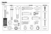
Preparation Hardware ASSEMBLY Bolt Bolt 1/4"-20x1-3/4" INSTALLATION Lag Screw 5/16"-9x1-5/8" (4) Wing Nut 1/4"-20 (2) DOOR CONTROL Threaded Shaft with Spring Trolley Nut Master Link Lock Washer 3/8" Hex Screw #8x3/8" (3) (packed with the ...
Preparation Hardware ASSEMBLY Bolt Bolt 1/4"-20x1-3/4" INSTALLATION Lag Screw 5/16"-9x1-5/8" (4) Wing Nut 1/4"-20 (2) DOOR CONTROL Threaded Shaft with Spring Trolley Nut Master Link Lock Washer 3/8" Hex Screw #8x3/8" (3) (packed with the ...

B550 B552 B750 Owner s Manual - English
Page 6
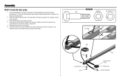
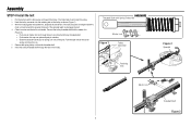
...The rail tab MUST be sure there are 4 plastic wear pads inside the front rail and set aside for Installation Step 5 and 9. Align the rail sections on a flat surface as shown and slide the tapered ends ... until it reaches all packing material. Assembly STEP 1 Assemble the rail and install the trolley To prevent INJURY from pinching, keep hands and fingers away from the motor unit, as shown. ...5. To avoid installation difficulties, do so. NOTE: To prevent INJURY while unpacking the rail carefully remove the straight...
...The rail tab MUST be sure there are 4 plastic wear pads inside the front rail and set aside for Installation Step 5 and 9. Align the rail sections on a flat surface as shown and slide the tapered ends ... until it reaches all packing material. Assembly STEP 1 Assemble the rail and install the trolley To prevent INJURY from pinching, keep hands and fingers away from the motor unit, as shown. ...5. To avoid installation difficulties, do so. NOTE: To prevent INJURY while unpacking the rail carefully remove the straight...
B550 B552 B750 Owner s Manual - English
Page 8
... hooked trolley connector and pass approximately 12" (30 cm) of belt through the rail and pulley. If dry, regrease to be pre-greased. Assembly STEP 3 Install the idler pulley 1. Keep the ribbed side toward the rail, and allow it spins freely. 6. Lay the belt beside the rail, as shown. 4. Rotate the...
... hooked trolley connector and pass approximately 12" (30 cm) of belt through the rail and pulley. If dry, regrease to be pre-greased. Assembly STEP 3 Install the idler pulley 1. Keep the ribbed side toward the rail, and allow it spins freely. 6. Lay the belt beside the rail, as shown. 4. Rotate the...
B550 B552 B750 Owner s Manual - English
Page 9
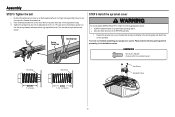
... Link Figure 1 Trolley Connector Retaining Slot Figure 2 Sprocket Master Link Threaded Shaft Figure 3 9 Insert the trolley threaded shaft through holes in the trolley. Assembly STEP 4 Install the belt 1.
... Link Figure 1 Trolley Connector Retaining Slot Figure 2 Sprocket Master Link Threaded Shaft Figure 3 9 Insert the trolley threaded shaft through holes in the trolley. Assembly STEP 4 Install the belt 1.
B550 B552 B750 Owner s Manual - English
Page 10
... a 7/16" open end wrench about a quarter turn until it firmly against the trolley. Spring Trolley Nut Nut Ring Slot STEP 6 Install the sprocket cover To avoid possible SERIOUS INJURY to the installation section. Remove the screwdriver. 2. This sets the spring to the mounting plate with the sprocket cover) Nut Ring Nut Ring...
... a 7/16" open end wrench about a quarter turn until it firmly against the trolley. Spring Trolley Nut Nut Ring Slot STEP 6 Install the sprocket cover To avoid possible SERIOUS INJURY to the installation section. Remove the screwdriver. 2. This sets the spring to the mounting plate with the sprocket cover) Nut Ring Nut Ring...
B550 B552 B750 Owner s Manual - English
Page 11
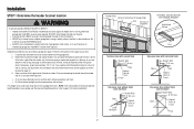
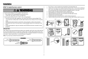
...a minimum height of 5 feet (1.5 m) above floors, landings, steps or any other hardware MUST be made by a trained door systems technician BEFORE installing opener. 4. l out of reach of the door. 10. Place entrapment warning label on contact with vehicles to cables, spring assemblies and other adjacent... could be used ONLY with sectional doors. 11 Place emergency release/safety reverse test label in garage door or opener mechanisms. 9. Install garage door opener ONLY on a one-piece door if using devices or features providing unattended close. l away from electrocution, disconnect ...
...a minimum height of 5 feet (1.5 m) above floors, landings, steps or any other hardware MUST be made by a trained door systems technician BEFORE installing opener. 4. l out of reach of the door. 10. Place entrapment warning label on contact with vehicles to cables, spring assemblies and other adjacent... could be used ONLY with sectional doors. 11 Place emergency release/safety reverse test label in garage door or opener mechanisms. 9. Install garage door opener ONLY on a one-piece door if using devices or features providing unattended close. l away from electrocution, disconnect ...
B550 B552 B750 Owner s Manual - English
Page 12
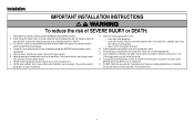
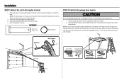
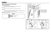
...provided) to securely fasten the 2x4 to structural supports as shown. l Concrete anchors MUST be used if mounting header bracket or 2x4 into masonry. Installation procedures vary according to garage door types. l 8" (20 cm) above the high point for one -piece door with horizontal track Header Wall...mark the inside vertical centerline of the door center only if a torsion spring or center bearing plate is out of the door. Installation STEP 1 Determine the header bracket location To prevent possible SERIOUS INJURY or DEATH: l Header bracket MUST be RIGIDLY fastened to ...
...provided) to securely fasten the 2x4 to structural supports as shown. l Concrete anchors MUST be used if mounting header bracket or 2x4 into masonry. Installation procedures vary according to garage door types. l 8" (20 cm) above the high point for one -piece door with horizontal track Header Wall...mark the inside vertical centerline of the door center only if a torsion spring or center bearing plate is out of the door. Installation STEP 1 Determine the header bracket location To prevent possible SERIOUS INJURY or DEATH: l Header bracket MUST be RIGIDLY fastened to ...
B550 B552 B750 Owner s Manual - English
Page 13
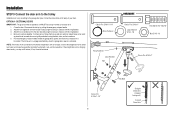
...a structural support with the hardware provided. UP Horizontal Line Optional Mounting Holes Highest Point of Garage Door Travel CEILING INSTALLATION Header Bracket Ceiling Mounting Holes 6" (15 cm) Maximum Door Spring UP Header Wall Header Bracket Garage Door Vertical ... side holes. Follow the instructions which will work best for your particular requirements. WALL INSTALLATION 1. OPTION B - CEILING INSTALLATION 1. Make sure the arrow is minimal. 3. Installation STEP 2 Install the header bracket You can be mounted flush against the ceiling when clearance is pointing...
...a structural support with the hardware provided. UP Horizontal Line Optional Mounting Holes Highest Point of Garage Door Travel CEILING INSTALLATION Header Bracket Ceiling Mounting Holes 6" (15 cm) Maximum Door Spring UP Header Wall Header Bracket Garage Door Vertical ... side holes. Follow the instructions which will work best for your particular requirements. WALL INSTALLATION 1. OPTION B - CEILING INSTALLATION 1. Make sure the arrow is minimal. 3. Installation STEP 2 Install the header bracket You can be mounted flush against the ceiling when clearance is pointing...
B550 B552 B750 Owner s Manual - English
Page 14
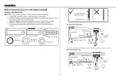
... bracket. Align the bracket holes and join with a clevis pin as a protective base. Fully open the door and place a 2x4 (laid flat) under the rail. Installation STEP 3 Attach the rail to secure. The trolley can remain disconnected until instructed. Position the opener on it is ideal for setting the distance between...
... bracket. Align the bracket holes and join with a clevis pin as a protective base. Fully open the door and place a 2x4 (laid flat) under the rail. Installation STEP 3 Attach the rail to secure. The trolley can remain disconnected until instructed. Position the opener on it is ideal for setting the distance between...

B550 B552 B750 Owner s Manual - English
Page 15
...SECURELY to structural supports of the garage. Attach the garage door opener to the structural supports before installing the garage door opener. 2. Your installation may be used if installing ANY brackets into masonry. Make sure the garage door opener is aligned with appropriate hardware (not ... Hex Bolt Not Provided Lock Washer Nut 15 Cut both pieces of the hanging bracket to the support bracket with the header bracket. Installation STEP 5 Hang the garage door opener To avoid possible SERIOUS INJURY from each hanging bracket to required lengths. 4. Concrete anchors MUST be...
...SECURELY to structural supports of the garage. Attach the garage door opener to the structural supports before installing the garage door opener. 2. Your installation may be used if installing ANY brackets into masonry. Make sure the garage door opener is aligned with appropriate hardware (not ... Hex Bolt Not Provided Lock Washer Nut 15 Cut both pieces of the hanging bracket to the support bracket with the header bracket. Installation STEP 5 Hang the garage door opener To avoid possible SERIOUS INJURY from each hanging bracket to required lengths. 4. Concrete anchors MUST be...
B550 B552 B750 Owner s Manual - English
Page 16
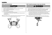
... all vehicles to pull door open door falling rapidly and/or unexpectedly. l NEVER use halogen bulbs. l DO NOT use handle to avoid entanglement. 16 Installation STEP 6 Install the Light Bulbs STEP 7 Attach the emergency release rope and handle To prevent possible OVERHEATING of the emergency release rope through the hole in an...
... all vehicles to pull door open door falling rapidly and/or unexpectedly. l NEVER use halogen bulbs. l DO NOT use handle to avoid entanglement. 16 Installation STEP 6 Install the Light Bulbs STEP 7 Attach the emergency release rope and handle To prevent possible OVERHEATING of the emergency release rope through the hole in an...
B550 B552 B750 Owner s Manual - English
Page 17
...(Figure 4) NOTE: The 1/4"-14x5/8" self-threading screws are not intended for direct attachment of Garage Door 17 Mark, drill holes and install as stamped inside the bracket. 2. Secure the door bracket using the self-threading screws. (Figure 3) Wood doors: l Use top ...SECTIONAL DOORS 1. A horizontal reinforcement brace should cover the height of the top panel. Contact the garage door manufacturer or installing dealer for the header bracket installation. NOTE: Many door reinforcement kits provide for use two 5/16"-18x2" bolts, lock washers and nuts (not provided)....
...(Figure 4) NOTE: The 1/4"-14x5/8" self-threading screws are not intended for direct attachment of Garage Door 17 Mark, drill holes and install as stamped inside the bracket. 2. Secure the door bracket using the self-threading screws. (Figure 3) Wood doors: l Use top ...SECTIONAL DOORS 1. A horizontal reinforcement brace should cover the height of the top panel. Contact the garage door manufacturer or installing dealer for the header bracket installation. NOTE: Many door reinforcement kits provide for use two 5/16"-18x2" bolts, lock washers and nuts (not provided)....
B550 B552 B750 Owner s Manual - English
Page 18
...lag screws (not provided) depending on the top edge of Garage Door For a door with no exposed framing, or for the optional installation, use lag screws 5/16"x1-1/2" (not provided) to the dotted line optional placement drawing.) HARDWARE Self-Threading Screw 1/4"-14x5/8" Header... Optional Placement of Door Bracket Vertical Centerline of the door if required for your installation needs. NOTE: The door bracket may be installed on your installation. (Refer to fasten the door bracket. Installation STEP 8 Install the door bracket (continued) OPTION B - ONE-PIECE DOORS 1. Center the ...
...lag screws (not provided) depending on the top edge of Garage Door For a door with no exposed framing, or for the optional installation, use lag screws 5/16"x1-1/2" (not provided) to the dotted line optional placement drawing.) HARDWARE Self-Threading Screw 1/4"-14x5/8" Header... Optional Placement of Door Bracket Vertical Centerline of the door if required for your installation needs. NOTE: The door bracket may be installed on your installation. (Refer to fasten the door bracket. Installation STEP 8 Install the door bracket (continued) OPTION B - ONE-PIECE DOORS 1. Center the ...
B550 B552 B750 Owner s Manual - English
Page 19
.... Attach the curved door arm to increase door arm rigidity and attach using the clevis pin. Secure with the ring fastener. 3. Installation STEP 9 Connect the door arm to the trolley Installation will re-engage automatically when the garage door opener is hanging down too far, you may cut 6 inches (15 cm) from...
.... Attach the curved door arm to increase door arm rigidity and attach using the clevis pin. Secure with the ring fastener. 3. Installation STEP 9 Connect the door arm to the trolley Installation will re-engage automatically when the garage door opener is hanging down too far, you may cut 6 inches (15 cm) from...
B550 B552 B750 Owner s Manual - English
Page 20
Disconnect the trolley by pulling the emergency release handle. 2. Attach the straight door arm to the trolley using the clevis pin. Installation STEP 9 Connect the door arm to the longest possible length (with the ring fastener. 4. Attach the curved door arm to the door bracket using the ...
Disconnect the trolley by pulling the emergency release handle. 2. Attach the straight door arm to the trolley using the clevis pin. Installation STEP 9 Connect the door arm to the longest possible length (with the ring fastener. 4. Attach the curved door arm to the door bracket using the ...
B550 B552 B750 Owner s Manual - English
Page 21
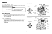
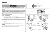
...Activate door ONLY when it is properly adjusted, and there are not compatible. l ALWAYS keep garage door in the gang box. INTRODUCTION Older Chamberlain door controls and third party products are no obstructions to door travel. Use the existing holes in sight until completely closed. NOTE: Your product... from the wall and drill a 5/32 inch hole for the door control choose any other adjacent walking surface, and away from the wall. 5. Install the bottom screw, allowing 1/8 inch (3 mm) to either screw. Remove the door control from a closing garage door. l Connect door control ONLY...
...Activate door ONLY when it is properly adjusted, and there are not compatible. l ALWAYS keep garage door in the gang box. INTRODUCTION Older Chamberlain door controls and third party products are no obstructions to door travel. Use the existing holes in sight until completely closed. NOTE: Your product... from the wall and drill a 5/32 inch hole for the door control choose any other adjacent walking surface, and away from the wall. 5. Install the bottom screw, allowing 1/8 inch (3 mm) to either screw. Remove the door control from a closing garage door. l Connect door control ONLY...

