WINDSONIC 2-D Sonic Wind Sensors
Page 6
... Connections 12 7-5. A declination angle east of True North (positive) is subtracted from 0 to 1 26 A-1. WindSonic1 to SDM-SIO1 Connections 11 7-4. WindSonic Orientation A-1 A.1 Determining True North and Sensor Orientation A-1 A.2 Online Magnetic Declination Calculator A-3 B. White dot indicating ...Siting References 28 Appendices A. NOAA web calculator A-3 Tables 7-1. WindSonic1 to Datalogger Connections 11 7-3. Table of True North (negative) is subtracted from 0 to find True North A-2 A-4. WindSonic mounted on an Edlog array-based datalogger (CR10X) using ...
... Connections 12 7-5. A declination angle east of True North (positive) is subtracted from 0 to 1 26 A-1. WindSonic1 to SDM-SIO1 Connections 11 7-4. WindSonic Orientation A-1 A.1 Determining True North and Sensor Orientation A-1 A.2 Online Magnetic Declination Calculator A-3 B. White dot indicating ...Siting References 28 Appendices A. NOAA web calculator A-3 Tables 7-1. WindSonic1 to Datalogger Connections 11 7-3. Table of True North (negative) is subtracted from 0 to find True North A-2 A-4. WindSonic mounted on an Edlog array-based datalogger (CR10X) using ...
WINDSONIC 2-D Sonic Wind Sensors
Page 7
WindSonic Data Format Option 15 7-9. Example Datalogger Program Diagnostic Codes 27 iii Command 16 7-10. Wiring for CR800 Program Example 21 9-1. Gill WindSonic Diagnostic Codes 27 9-2. Wiring for CR10(X) Program Example 17 7-11. Table of Contents 7-8. Datalogger Operating Systems that Support the SDI-12 "aRo!" Wiring for CR200(X) Program Example 20 7-12.
WindSonic Data Format Option 15 7-9. Example Datalogger Program Diagnostic Codes 27 iii Command 16 7-10. Wiring for CR800 Program Example 21 9-1. Gill WindSonic Diagnostic Codes 27 9-2. Wiring for CR10(X) Program Example 17 7-11. Table of Contents 7-8. Datalogger Operating Systems that Support the SDI-12 "aRo!" Wiring for CR200(X) Program Example 20 7-12.
WINDSONIC 2-D Sonic Wind Sensors
Page 9
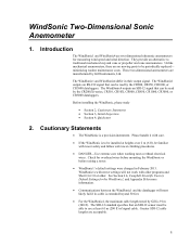
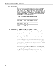
... at least 61 m (200 ft) of signal cable. Check for overhead wires before mounting the WindSonic or before raising a tower. • WindSonic1's default settings were changed in their output signal. See Section 6.4, Campbell Scientific Factory Default Settings for the WindSonic1, and Appendix B for measuring wind speed and wind direction. Greater SDI-12 cable lengths are...
... at least 61 m (200 ft) of signal cable. Check for overhead wires before mounting the WindSonic or before raising a tower. • WindSonic1's default settings were changed in their output signal. See Section 6.4, Campbell Scientific Factory Default Settings for the WindSonic1, and Appendix B for measuring wind speed and wind direction. Greater SDI-12 cable lengths are...

WINDSONIC 2-D Sonic Wind Sensors
Page 10
This compound was chosen for damage. Contact Campbell Scientific about any discrepancies. • The model number and cable length are received. 3.1 Ships With The WindSonic is shipped with the ResourceDVD and a mounting kit (pn 17387). Check this jacket will pass FMVSS302. See Section 10, Siting...nearest obstruction should be ten times the height of the cable. If it is Santoprene® rubber. Quickstart 4.1 Siting Locate the WindSonic away from obstructions such as slow burning when tested according to the male mating connector located on the bottom of tubing (pn 17386...
This compound was chosen for damage. Contact Campbell Scientific about any discrepancies. • The model number and cable length are received. 3.1 Ships With The WindSonic is shipped with the ResourceDVD and a mounting kit (pn 17387). Check this jacket will pass FMVSS302. See Section 10, Siting...nearest obstruction should be ten times the height of the cable. If it is Santoprene® rubber. Quickstart 4.1 Siting Locate the WindSonic away from obstructions such as slow burning when tested according to the male mating connector located on the bottom of tubing (pn 17386...

WINDSONIC 2-D Sonic Wind Sensors
Page 11
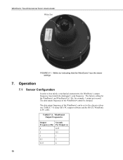
... along the underside of the crossarm to the tripod or tower, and to True North (see FIGURE 4-1). Orient the WindSonic so that the colored North marker arrows point to the instrument enclosure. 8. WindSonic Two-Dimensional Sonic Anemometer 5. Colored North Marker Arrows Pointing North FIGURE 4-1. Appendix A contains detailed information on a CM202 using a compass...
... along the underside of the crossarm to the tripod or tower, and to True North (see FIGURE 4-1). Orient the WindSonic so that the colored North marker arrows point to the instrument enclosure. 8. WindSonic Two-Dimensional Sonic Anemometer 5. Colored North Marker Arrows Pointing North FIGURE 4-1. Appendix A contains detailed information on a CM202 using a compass...
WINDSONIC 2-D Sonic Wind Sensors
Page 12
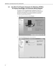
Open Short Cut and click on New Program. 2. Select the datalogger and enter the scan interval. 4 See Section 7, Operation, for programming the datalogger to measure the WindSonic is to Program Datalogger and Generate Wiring Diagram The simplest method for WindSonic1 programming information and additional WindSonic4 programming information. 1. This section provides information about using Short Cut with the WindSonic4. WindSonic Two-Dimensional Sonic Anemometer 4.3 Use Short Cut Program Generator for Windows (SCWin) to use Campbell Scientific's SCWin.
Open Short Cut and click on New Program. 2. Select the datalogger and enter the scan interval. 4 See Section 7, Operation, for programming the datalogger to measure the WindSonic is to Program Datalogger and Generate Wiring Diagram The simplest method for WindSonic1 programming information and additional WindSonic4 programming information. 1. This section provides information about using Short Cut with the WindSonic4. WindSonic Two-Dimensional Sonic Anemometer 4.3 Use Short Cut Program Generator for Windows (SCWin) to use Campbell Scientific's SCWin.

WINDSONIC 2-D Sonic Wind Sensors
Page 13
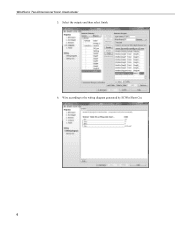
WindSonic Two-Dimensional Sonic Anemometer 3. Variables default to 0. The SDI12 Address defaults to WindDir, WS_ms, and WSDiag that hold the wind direction measurements, wind speed measurements, and diagnostic code. Define the name of sensors to be measured then select next. 4. Units default to the list of the public variables and SDI-12 Address. Select WindSonic4 (SDI-12) Two Dimensional Ultrasonic Wind Sensor and select the right arrow (in center of screen) to add it to meters/seconds. 5 Select the desired units of measurement for the wind speed.
WindSonic Two-Dimensional Sonic Anemometer 3. Variables default to 0. The SDI12 Address defaults to WindDir, WS_ms, and WSDiag that hold the wind direction measurements, wind speed measurements, and diagnostic code. Define the name of sensors to be measured then select next. 4. Units default to the list of the public variables and SDI-12 Address. Select WindSonic4 (SDI-12) Two Dimensional Ultrasonic Wind Sensor and select the right arrow (in center of screen) to add it to meters/seconds. 5 Select the desired units of measurement for the wind speed.
WINDSONIC 2-D Sonic Wind Sensors
Page 14
WindSonic Two-Dimensional Sonic Anemometer 5. Select the outputs and then select finish. 6. Wire according to the wiring diagram generated by SCWin Short Cut. 6
WindSonic Two-Dimensional Sonic Anemometer 5. Select the outputs and then select finish. 6. Wire according to the wiring diagram generated by SCWin Short Cut. 6
WINDSONIC 2-D Sonic Wind Sensors
Page 15
... be connected to the CR800-series control ports (COMn). SDI-12 is used for more information. Option 1 WindSonic (WindSonic1) outputs data using the SDI-12 interface. The WindSonic1 connects to a PC running Gill's PC support software. Campbell Scientific recommends that the WindSonic4, SDI-12 interface, be interfaced using the SDM-SIO1. A serial cable (WINDSONICRCBL-L) is...
... be connected to the CR800-series control ports (COMn). SDI-12 is used for more information. Option 1 WindSonic (WindSonic1) outputs data using the SDI-12 interface. The WindSonic1 connects to a PC running Gill's PC support software. Campbell Scientific recommends that the WindSonic4, SDI-12 interface, be interfaced using the SDM-SIO1. A serial cable (WINDSONICRCBL-L) is...
WINDSONIC 2-D Sonic Wind Sensors
Page 16
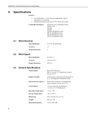
WindSonic Two-Dimensional Sonic Anemometer 6. Specifications Features: • Low maintenance-no moving parts significantly reduces maintenance cost and time • Minimum detectable wind speed of 0.01 ...: Output Resolution: 0 to 359° (no dead band) ±3° 1° 6.2 Wind Speed Operating Range: Accuracy: Output Resolution: 0 to 1 Hz Current Drain: ~15 mA continuous (WindSonic1) address factory set to 0 Output Variables: wind direction, wind speed, and diagnostic or ux, uy, and diagnostic (WindSonic4 only) Measurement Frequency: 40 Hz block averaged...
WindSonic Two-Dimensional Sonic Anemometer 6. Specifications Features: • Low maintenance-no moving parts significantly reduces maintenance cost and time • Minimum detectable wind speed of 0.01 ...: Output Resolution: 0 to 359° (no dead band) ±3° 1° 6.2 Wind Speed Operating Range: Accuracy: Output Resolution: 0 to 1 Hz Current Drain: ~15 mA continuous (WindSonic1) address factory set to 0 Output Variables: wind direction, wind speed, and diagnostic or ux, uy, and diagnostic (WindSonic4 only) Measurement Frequency: 40 Hz block averaged...
WINDSONIC 2-D Sonic Wind Sensors
Page 17
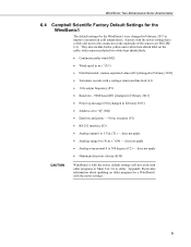
...Appendix B provides information about updating an older program for the WindSonic1 were changed in February 2013 to 5 Vdc (T1) - does not apply • Minimum direction velocity (K50) CAUTION WindSonic1s with the newer default settings will not work with the newer...232 interface (E3) • Analog output 0 to improve operation in cold temperatures. WindSonic Two-Dimensional Sonic Anemometer 6.4 Campbell Scientific Factory Default Settings for the WindSonic1 The default settings for a WindSonic1 with older programs or Short Cut 3.0 or older. older sensors included two white ...
...Appendix B provides information about updating an older program for the WindSonic1 were changed in February 2013 to 5 Vdc (T1) - does not apply • Minimum direction velocity (K50) CAUTION WindSonic1s with the newer default settings will not work with the newer...232 interface (E3) • Analog output 0 to improve operation in cold temperatures. WindSonic Two-Dimensional Sonic Anemometer 6.4 Campbell Scientific Factory Default Settings for the WindSonic1 The default settings for a WindSonic1 with older programs or Short Cut 3.0 or older. older sensors included two white ...
WINDSONIC 2-D Sonic Wind Sensors
Page 18
... values (see TABLE 7-1) using Gill's PC support software and the RS-232 WindSonic to best mimic a mechanical anemometer, the WindSonic's output frequency must match the datalogger's scan frequency. WindSonic1 Output Frequencies Output Seconds Frequency (Hz) Per Output (s) 4 0.25 2 0.5 1 1 0.5 2 0.25 4 10 WindSonic Two-Dimensional Sonic Anemometer White Dot FIGURE 6-1. The factory setting for example, 1 output...
... values (see TABLE 7-1) using Gill's PC support software and the RS-232 WindSonic to best mimic a mechanical anemometer, the WindSonic's output frequency must match the datalogger's scan frequency. WindSonic1 Output Frequencies Output Seconds Frequency (Hz) Per Output (s) 4 0.25 2 0.5 1 1 0.5 2 0.25 4 10 WindSonic Two-Dimensional Sonic Anemometer White Dot FIGURE 6-1. The factory setting for example, 1 output...
WINDSONIC 2-D Sonic Wind Sensors
Page 19
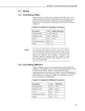
... SDM peripherals. At a 1 Hz measurement rate, a maximum of thumb is a Campbell Scientific digital communications protocol used with dedicated UART hardware on the baud rate, the nominal resistance of the wire, the capacitance between conductors, and the capacitance between a WindSonic1 and SDM-SIO1. WindSonic Two-Dimensional Sonic Anemometer 7.2 Wiring 7.2.1 Serial Wiring (COMn) CRBasic dataloggers (CR800...
... SDM peripherals. At a 1 Hz measurement rate, a maximum of thumb is a Campbell Scientific digital communications protocol used with dedicated UART hardware on the baud rate, the nominal resistance of the wire, the capacitance between conductors, and the capacitance between a WindSonic1 and SDM-SIO1. WindSonic Two-Dimensional Sonic Anemometer 7.2 Wiring 7.2.1 Serial Wiring (COMn) CRBasic dataloggers (CR800...
WINDSONIC 2-D Sonic Wind Sensors
Page 20
... support serial communication using control ports and the SerialInRecord(). The datalogger and WindSonic1 each other and will occur if the WindSonic is a three-wire interface used between processor-based sensors and digital recorders (TABLE 7-4). These clocks are available on the Campbell Scientific website in this manual record the number of phase. This ensures that...
... support serial communication using control ports and the SerialInRecord(). The datalogger and WindSonic1 each other and will occur if the WindSonic is a three-wire interface used between processor-based sensors and digital recorders (TABLE 7-4). These clocks are available on the Campbell Scientific website in this manual record the number of phase. This ensures that...
WINDSONIC 2-D Sonic Wind Sensors
Page 21
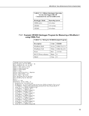
...CR800-series CR1000 CR3000 Operating System 4.0 or later 13.0 or later 6.0 or later 7.3.1 Example CR1000 Datalogger Program for CR1000 Example Program Description WindSonic RxD WindSonic TxD Power RS-232/Power reference Shield Color Green White Red Black Clear CR1000 COM1 Tx (C1) COM1 Rx (C2) +12 Vdc ...diag4) FieldNames ("diag_4_TOT") Totalize (1,n,IEEE4,diag8) FieldNames ("diag_8_TOT") Totalize (1,n,IEEE4,diag9) FieldNames ("diag_9_TOT") Totalize (1,n,IEEE4,diag10) 13 Wiring for Measuring a WindSonic1 using COMn Port TABLE 7-6. WindSonic Two-Dimensional Sonic Anemometer TABLE 7-5.
...CR800-series CR1000 CR3000 Operating System 4.0 or later 13.0 or later 6.0 or later 7.3.1 Example CR1000 Datalogger Program for CR1000 Example Program Description WindSonic RxD WindSonic TxD Power RS-232/Power reference Shield Color Green White Red Black Clear CR1000 COM1 Tx (C1) COM1 Rx (C2) +12 Vdc ...diag4) FieldNames ("diag_4_TOT") Totalize (1,n,IEEE4,diag8) FieldNames ("diag_8_TOT") Totalize (1,n,IEEE4,diag9) FieldNames ("diag_9_TOT") Totalize (1,n,IEEE4,diag10) 13 Wiring for Measuring a WindSonic1 using COMn Port TABLE 7-6. WindSonic Two-Dimensional Sonic Anemometer TABLE 7-5.
WINDSONIC 2-D Sonic Wind Sensors
Page 22
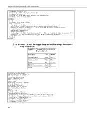
...nmbr_bytes_rtrnd=0) OR (diag0) ) CallTable stats NextScan EndProg 7.3.2 Example CR1000 Datalogger Program for CR1000/SDM-SIO1 Program Example Description WindSonic RxD WindSonic TxD Power RS-232/Power reference Shield Color Green White Red Black Clear CR1000 TX-Z RX-A +12 Vdc G ... BeginProg n = 1 SerialOpen (Com1,9600,3,0,108) Scan (1,Sec,3,0) 'Get data from WindSonic. Wiring for Measuring a WindSonic1 using an SDM-SIO1 TABLE 7-7. SerialInRecord (Com1,in_bytes_str,&h02,0,&h0D0A,nmbr_bytes_rtrnd,01) SplitStr (windsonic(),in_bytes_str,",",4,4) 'Split the string and convert to floats.
...nmbr_bytes_rtrnd=0) OR (diag0) ) CallTable stats NextScan EndProg 7.3.2 Example CR1000 Datalogger Program for CR1000/SDM-SIO1 Program Example Description WindSonic RxD WindSonic TxD Power RS-232/Power reference Shield Color Green White Red Black Clear CR1000 TX-Z RX-A +12 Vdc G ... BeginProg n = 1 SerialOpen (Com1,9600,3,0,108) Scan (1,Sec,3,0) 'Get data from WindSonic. Wiring for Measuring a WindSonic1 using an SDM-SIO1 TABLE 7-7. SerialInRecord (Com1,in_bytes_str,&h02,0,&h0D0A,nmbr_bytes_rtrnd,01) SplitStr (windsonic(),in_bytes_str,",",4,4) 'Split the string and convert to floats.
WINDSONIC 2-D Sonic Wind Sensors
Page 23
...Section 4.3, Use Short Cut Program Generator for Windows (SCWin) to Program Datalogger and Generate Wiring Diagram, describes using SCWin. WindSonic Two-Dimensional Sonic Anemometer Totalize (1,n,IEEE4,diag2) FieldNames ("diag_2_TOT") Totalize (1,n,IEEE4,diag4) FieldNames ("diag_4_TOT") Totalize (1,n,IEEE4,diag8)... (40,9600,3,0,108) 'SDM-SIO1 SDM address set To 8. SerialInRecord (40,in_bytes_str,&h02,0,&h0D0A,nmbr_bytes_rtrnd,01) SplitStr (windsonic(),in_bytes_str,",",4,4) 'Split the string and convert to create a datalogger program and wiring diagram for the WindSonic4 can be written ...
...Section 4.3, Use Short Cut Program Generator for Windows (SCWin) to Program Datalogger and Generate Wiring Diagram, describes using SCWin. WindSonic Two-Dimensional Sonic Anemometer Totalize (1,n,IEEE4,diag2) FieldNames ("diag_2_TOT") Totalize (1,n,IEEE4,diag4) FieldNames ("diag_4_TOT") Totalize (1,n,IEEE4,diag8)... (40,9600,3,0,108) 'SDM-SIO1 SDM address set To 8. SerialInRecord (40,in_bytes_str,&h02,0,&h0D0A,nmbr_bytes_rtrnd,01) SplitStr (windsonic(),in_bytes_str,",",4,4) 'Split the string and convert to create a datalogger program and wiring diagram for the WindSonic4 can be written ...
WINDSONIC 2-D Sonic Wind Sensors
Page 24
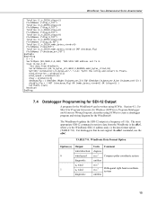
... the most current datalogger operating systems are available at 1 Hz. command is used, it takes the WindSonic approximately 190 milliseconds ±10 milliseconds to retrieve the data because of the additional handshaking required with three...later 16 Datalogger Operating Systems that supports the SDI12 aRo! TABLE 7-9. WindSonic Two-Dimensional Sonic Anemometer CAUTION The WindSonic4 returns three data points; The most current wind measurements to 4 WindSonic4s at the Campbell Scientific website in the Support|Downloads section. If the aDo! For all practical...
... the most current datalogger operating systems are available at 1 Hz. command is used, it takes the WindSonic approximately 190 milliseconds ±10 milliseconds to retrieve the data because of the additional handshaking required with three...later 16 Datalogger Operating Systems that supports the SDI12 aRo! TABLE 7-9. WindSonic Two-Dimensional Sonic Anemometer CAUTION The WindSonic4 returns three data points; The most current wind measurements to 4 WindSonic4s at the Campbell Scientific website in the Support|Downloads section. If the aDo! For all practical...

WINDSONIC 2-D Sonic Wind Sensors
Page 25
WindSonic Two-Dimensional Sonic Anemometer 7.4.1 Example CR10X (Edlog) Datalogger Program for CR10(X) Program Example Description SDI-12 data SDI-12 power SDI-12 reference Shield Color ...
WindSonic Two-Dimensional Sonic Anemometer 7.4.1 Example CR10X (Edlog) Datalogger Program for CR10(X) Program Example Description SDI-12 data SDI-12 power SDI-12 reference Shield Color ...

WINDSONIC 2-D Sonic Wind Sensors
Page 26
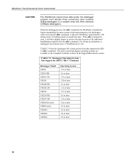
... Flag Low (Flag 9) ;Report the total of diag = 2. ; 14: Totalize (P72) 1: 1 Reps 2: 4 Loc [ samples ] 15: If (XF) (P89) 1: 3 X Loc [ ws_diag ] 2: 1 = 3: 4 F 4: 29 Set Intermed. Proc. Proc. WindSonic Two-Dimensional Sonic Anemometer 8: If (XF) (P89) 1: 3 X Loc [ ws_diag ] 2: 2 3: 0 F 4: 19 Set Intermed. Proc. Disable Flag High (Flag 9) 9: Wind Vector (P69) 1: 1 Reps 2: 0 Samples per Sub-Interval...
... Flag Low (Flag 9) ;Report the total of diag = 2. ; 14: Totalize (P72) 1: 1 Reps 2: 4 Loc [ samples ] 15: If (XF) (P89) 1: 3 X Loc [ ws_diag ] 2: 1 = 3: 4 F 4: 29 Set Intermed. Proc. Proc. WindSonic Two-Dimensional Sonic Anemometer 8: If (XF) (P89) 1: 3 X Loc [ ws_diag ] 2: 2 3: 0 F 4: 19 Set Intermed. Proc. Disable Flag High (Flag 9) 9: Wind Vector (P69) 1: 1 Reps 2: 0 Samples per Sub-Interval...
