CS120A Visibility Sensor
Page 5
... or installation work, inform all utility companies and have all electrical codes. WHILE EVERY ATTEMPT IS MADE TO EMBODY THE HIGHEST DEGREE OF SAFETY IN ALL CAMPBELL SCIENTIFIC PRODUCTS, THE CUSTOMER ASSUMES ALL RISK FROM ANY INJURY RESULTING FROM IMPROPER INSTALLATION, USE, OR MAINTENANCE OF TRIPODS, TOWERS, OR ATTACHMENTS TO TRIPODS AND TOWERS SUCH AS SENSORS, CROSSARMS, ENCLOSURES, ANTENNAS...
... or installation work, inform all utility companies and have all electrical codes. WHILE EVERY ATTEMPT IS MADE TO EMBODY THE HIGHEST DEGREE OF SAFETY IN ALL CAMPBELL SCIENTIFIC PRODUCTS, THE CUSTOMER ASSUMES ALL RISK FROM ANY INJURY RESULTING FROM IMPROPER INSTALLATION, USE, OR MAINTENANCE OF TRIPODS, TOWERS, OR ATTACHMENTS TO TRIPODS AND TOWERS SUCH AS SENSORS, CROSSARMS, ENCLOSURES, ANTENNAS...
CS120A Visibility Sensor
Page 9
... Safety 2 1.3 Sensor Unit Safety 2 2. Environmental specifications 5 6. Contents PDF viewers note: These page numbers refer to the printed version of the CS120A - Mechanical specifications 5 7. Installation procedure 5 7.1 Equipment grounding 7 7.2 Mounting the CS120A 7 7.3 Optional Campbell Scientific Mount 8 8. Technical specification 3 3. CS120A internal connectors' description 10 8.1 CS120A recommended wiring using Campbell Scientific cables ...........12 9. Functions of the internal switches 15 10. Device Configuration Utility/Command Line/Menu 19 11.1 Configuring...
... Safety 2 1.3 Sensor Unit Safety 2 2. Environmental specifications 5 6. Contents PDF viewers note: These page numbers refer to the printed version of the CS120A - Mechanical specifications 5 7. Installation procedure 5 7.1 Equipment grounding 7 7.2 Mounting the CS120A 7 7.3 Optional Campbell Scientific Mount 8 8. Technical specification 3 3. CS120A internal connectors' description 10 8.1 CS120A recommended wiring using Campbell Scientific cables ...........12 9. Functions of the internal switches 15 10. Device Configuration Utility/Command Line/Menu 19 11.1 Configuring...

CS120A Visibility Sensor
Page 10
... command 24 13.4 The POLL command - Definition of the variables that can be set by the user on the CS120A 20 13. 12. Lubricating the enclosure screws 35 19. Example CRBasic programs C-1 ii Calibrating the CS120A 30 16. Performing an operating system update 34 17. CS120A block diagram A-1 B. Polling the CS120A 26 14. Entering the CS120A menu system 27 15. Cleaning 34 18.
... command 24 13.4 The POLL command - Definition of the variables that can be set by the user on the CS120A 20 13. 12. Lubricating the enclosure screws 35 19. Example CRBasic programs C-1 ii Calibrating the CS120A 30 16. Performing an operating system update 34 17. CS120A block diagram A-1 B. Polling the CS120A 26 14. Entering the CS120A menu system 27 15. Cleaning 34 18.

CS120A Visibility Sensor
Page 12
CS120A Visibility Sensor 1.2 General Safety This manual provides important safety considerations for safety before leaving the factory and contains no internally replaceable or modifiable parts. Ignoring these cautions could expose users to the sensor unit. In normal operation they will lead to serious hazards. NOTE Notes highlight useful information in injury or death and/or irrevocable damage to dangerous light levels and...
CS120A Visibility Sensor 1.2 General Safety This manual provides important safety considerations for safety before leaving the factory and contains no internally replaceable or modifiable parts. Ignoring these cautions could expose users to the sensor unit. In normal operation they will lead to serious hazards. NOTE Notes highlight useful information in injury or death and/or irrevocable damage to dangerous light levels and...
CS120A Visibility Sensor
Page 14
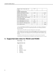
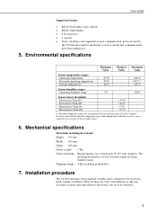
... RS232 and RS485 Serial setting 8N1 Supported data rates 1200 bps 2400 bps 9600 bps 19200 bps 38400 bps - default 57600 bps 115200 bps 4 This will reduce any parasitic currents and bring the two earths closer together if a direct connection cannot be further apart than this voltage. User output current - - 0.55V 32mA...
... RS232 and RS485 Serial setting 8N1 Supported data rates 1200 bps 2400 bps 9600 bps 19200 bps 38400 bps - default 57600 bps 115200 bps 4 This will reduce any parasitic currents and bring the two earths closer together if a direct connection cannot be further apart than this voltage. User output current - - 0.55V 32mA...
CS120A Visibility Sensor
Page 15
... the sensor has been tested by the CS120A have been understood 5. Some degradation of the extended ranges. 6. Shipping weight: 6 Kg (including packing box) 7. The mounting bracket has cut-outs for band clamps for larger diameter masts. User Guide Supported formats RS232 (Full duplex only), default RS485 (Half duplex) 8 bit data bytes 1 stop bit Parity...
... the sensor has been tested by the CS120A have been understood 5. Some degradation of the extended ranges. 6. Shipping weight: 6 Kg (including packing box) 7. The mounting bracket has cut-outs for band clamps for larger diameter masts. User Guide Supported formats RS232 (Full duplex only), default RS485 (Half duplex) 8 bit data bytes 1 stop bit Parity...

CS120A Visibility Sensor
Page 17
... Mounting the CS120A A pole mounting kit is supplied to allow band clamps to distort and/or damage the brackets by doing so, and/or the nuts may seize up into the sensor's sensing volume. The pole and foundations of cable is supplied ...manual for that will create false readings and erratic results. The power supply enclosure should be used with the sensor it should be mounted away from the sensor. Where the CS120A is connected to a suitable grounding point. If a power supply enclosure has been supplied with larger diameter masts. 7 User Guide NOTE If operating a CS120A...
... Mounting the CS120A A pole mounting kit is supplied to allow band clamps to distort and/or damage the brackets by doing so, and/or the nuts may seize up into the sensor's sensing volume. The pole and foundations of cable is supplied ...manual for that will create false readings and erratic results. The power supply enclosure should be used with the sensor it should be mounted away from the sensor. Where the CS120A is connected to a suitable grounding point. If a power supply enclosure has been supplied with larger diameter masts. 7 User Guide NOTE If operating a CS120A...

CS120A Visibility Sensor
Page 20
... heaters fitted with a PC serial port or USB to user alarms on connector C. In particular, additional RS485 communication should be used by the power/communications line. A configuration cable, part number 010817, is incorrectly wired to the CS120A then irrevocable damage can be twisted pair. If the power cable is available from Campbell Scientific that plugs directly into connector B, in place of the cable type supplied recommended. Please contact Campbell Scientific if you wish to the...
... heaters fitted with a PC serial port or USB to user alarms on connector C. In particular, additional RS485 communication should be used by the power/communications line. A configuration cable, part number 010817, is incorrectly wired to the CS120A then irrevocable damage can be twisted pair. If the power cable is available from Campbell Scientific that plugs directly into connector B, in place of the cable type supplied recommended. Please contact Campbell Scientific if you wish to the...
CS120A Visibility Sensor
Page 22
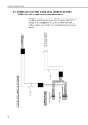
If another type of connection is required then the D-connector should be connected directly to a PC or to a datalogger such as the Campbell Scientific CR1000 using Campbell Scientific cables (this cable is terminated at one end with a 9 pin D-connector (DB9). The Dconnector can be removed. 12 CS120A Visibility Sensor 8.1 CS120A recommended wiring using a suitable interconnecting cable such as standard) The CS120A is provided pre-wired with a default 5 m power and communications cable which is supplied already connected as the SC110.
If another type of connection is required then the D-connector should be connected directly to a PC or to a datalogger such as the Campbell Scientific CR1000 using Campbell Scientific cables (this cable is terminated at one end with a 9 pin D-connector (DB9). The Dconnector can be removed. 12 CS120A Visibility Sensor 8.1 CS120A recommended wiring using a suitable interconnecting cable such as standard) The CS120A is provided pre-wired with a default 5 m power and communications cable which is supplied already connected as the SC110.

CS120A Visibility Sensor
Page 25
... for future use , set to OFF. 1 When switched to the ON position this switch temporarily sets the CS120A communications port to flash. This reset will affect all communication setting and will reset the CS120A to the ON position this switch will replace the user calibration settings with the factory defaults. These switches perform certain functions at least 10 seconds with four switches located within the main enclosure. User Guide 9. Internal switch functions Switch number Function 4 Reserved...
... for future use , set to OFF. 1 When switched to the ON position this switch temporarily sets the CS120A communications port to flash. This reset will affect all communication setting and will reset the CS120A to the ON position this switch will replace the user calibration settings with the factory defaults. These switches perform certain functions at least 10 seconds with four switches located within the main enclosure. User Guide 9. Internal switch functions Switch number Function 4 Reserved...

CS120A Visibility Sensor
Page 27
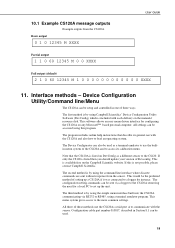
... is then used to calculate the MOR for RS485 networks. Those averages are not direct averages of MOR measurements but are updated at the chosen output interval or when...default. Contains all system alarms codes Sensor ID break down ID Definition 1 One minute average 10 Ten minute average In accordance with artificial obscurants or using the calibration disc. Zero by the sensor Visibility units break down ID Definition M Metres F Feet Averaging duration break down ID Definition 0-9 Unit number defined by the user to see quite rapid changes in continuous mode...
... is then used to calculate the MOR for RS485 networks. Those averages are not direct averages of MOR measurements but are updated at the chosen output interval or when...default. Contains all system alarms codes Sensor ID break down ID Definition 1 One minute average 10 Ten minute average In accordance with artificial obscurants or using the calibration disc. Zero by the sensor Visibility units break down ID Definition M Metres F Feet Averaging duration break down ID Definition 0-9 Unit number defined by the user to see quite rapid changes in continuous mode...
CS120A Visibility Sensor
Page 29
... online help instructions that the CS120A is listed on the Campbell Scientific website. If only the CS120 is by using this is available free on DevConfig as a terminal emulator to use the builtin menu system of the CS120A and to access its general use the CS120As serial port A to communicate with the CS120A and also how to load an operating system. All three of three ways. The configuration setting...
... online help instructions that the CS120A is listed on the Campbell Scientific website. If only the CS120 is by using this is available free on DevConfig as a terminal emulator to use the builtin menu system of the CS120A and to access its general use the CS120As serial port A to communicate with the CS120A and also how to load an operating system. All three of three ways. The configuration setting...
CS120A Visibility Sensor
Page 30
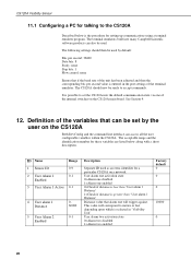
... are listed below along with a short description. Definition of the unit has been adjusted and then the corresponding bits per second value is greater than 'User alarm 1 Distance' Distance value that can access all the user configurable variables within the CS120A. The terminal emulators built into many Campbell Scientific software products can also be set by default: Bits per second: 38400 Data bits...
... are listed below along with a short description. Definition of the unit has been adjusted and then the corresponding bits per second value is greater than 'User alarm 1 Distance' Distance value that can access all the user configurable variables within the CS120A. The terminal emulators built into many Campbell Scientific software products can also be set by default: Bits per second: 38400 Data bits...

CS120A Visibility Sensor
Page 31
... one second in every two 3 = Sample one minute or ten. User Guide 6 User Alarm 2 Active 7 User alarm 2 Distance 8 Baud rate 9 Serial Number 10 Visibility Unit 11 Message Interval 12 Measurement mode 13 Message Format 14 Serial port protocol 15 Averaging period 16 Sample timing 17 Dew heater override 18 Hood heater override(1) 19 Dirty window compensation 0-1 0-60000 0-6 0-32000 M or F 1-3600 0-1 0-2 0-1 1 or 10 1-60 0-1 0-1 0-1 0=Check...
... one second in every two 3 = Sample one minute or ten. User Guide 6 User Alarm 2 Active 7 User alarm 2 Distance 8 Baud rate 9 Serial Number 10 Visibility Unit 11 Message Interval 12 Measurement mode 13 Message Format 14 Serial port protocol 15 Averaging period 16 Sample timing 17 Dew heater override 18 Hood heater override(1) 19 Dirty window compensation 0-1 0-60000 0-6 0-32000 M or F 1-3600 0-1 0-2 0-1 1 or 10 1-60 0-1 0-1 0-1 0=Check...

CS120A Visibility Sensor
Page 32
... more information on a regular basis e.g. The SET commands sets user settable values and the POLL command is enabled where possible, especially when long cable runs are GET, SET and POLL. The SET command and the 'Device Configuration Utility' software access identical settings within the CS120A, please refer to change the default power up state of received data against the checksum sent. CS120A Visibility Sensor 20 Use CRC...
... more information on a regular basis e.g. The SET commands sets user settable values and the POLL command is enabled where possible, especially when long cable runs are GET, SET and POLL. The SET command and the 'Device Configuration Utility' software access identical settings within the CS120A, please refer to change the default power up state of received data against the checksum sent. CS120A Visibility Sensor 20 Use CRC...

CS120A Visibility Sensor
Page 36
... Sample timing = 1 sample per second Dew heater override = 0 (CS120A will automatically control the dew heaters) Hood heater override = 0 (CS120A will automatically control the hood heaters) Dirty window compensation = 0 (dirty window compensation off) CRC checking on a keypad. (3) Not case sensitive. Example of this command depends on how the CS120A is configured using the SET command or the menu interfaces. Polling the CS120A The...
... Sample timing = 1 sample per second Dew heater override = 0 (CS120A will automatically control the dew heaters) Hood heater override = 0 (CS120A will automatically control the hood heaters) Dirty window compensation = 0 (dirty window compensation off) CRC checking on a keypad. (3) Not case sensitive. Example of this command depends on how the CS120A is configured using the SET command or the menu interfaces. Polling the CS120A The...
CS120A Visibility Sensor
Page 37
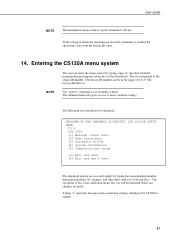
... informed before any changes are made . -> The displayed options are accessed simply by typing the corresponding number then pressing return. The excep(t0io)n tEoxthiits isatnhde cdaloibnr'attionsmaveneu, but you will be displayed: WELCOME TO THE CAMPBELL SCIENTIFIC LTD CS120A SETUP MENU ID 0 S/N 1009 (1) Message output menu (2) User alarm menu (3) Calibrate CS120A (4) System information (5) Communications setup The displayed options are made . No changes will take effect until you `Exit and Save'. The factory default...
... informed before any changes are made . -> The displayed options are accessed simply by typing the corresponding number then pressing return. The excep(t0io)n tEoxthiits isatnhde cdaloibnr'attionsmaveneu, but you will be displayed: WELCOME TO THE CAMPBELL SCIENTIFIC LTD CS120A SETUP MENU ID 0 S/N 1009 (1) Message output menu (2) User alarm menu (3) Calibrate CS120A (4) System information (5) Communications setup The displayed options are made . No changes will take effect until you `Exit and Save'. The factory default...
CS120A Visibility Sensor
Page 39
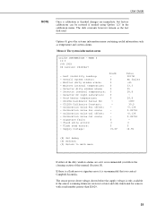
...: - Detector dirty window alarm: - CS120A Calibrator Constant: - Flash read errors: - Supply voltage: Alarm 0 0 0 0 0 0 0 0 0 0 Detector internal temperature: - Overall system status: - Detector DC light saturation: - CS120A Calibrator Serial No: - Calibration value Cal scale: - MENU 4 ID 0 S/N 1009 OS version: CS120Av7 - Last visibility reading: - Calibration value Cal offset: - User Guide NOTE Once a calibration is finished changes are immediate, but factory calibrations can be restored if needed using Option `(2)' in the calibration menu. The disk constants...
...: - Detector dirty window alarm: - CS120A Calibrator Constant: - Flash read errors: - Supply voltage: Alarm 0 0 0 0 0 0 0 0 0 0 Detector internal temperature: - Overall system status: - Detector DC light saturation: - CS120A Calibrator Serial No: - Calibration value Cal scale: - MENU 4 ID 0 S/N 1009 OS version: CS120Av7 - Last visibility reading: - Calibration value Cal offset: - User Guide NOTE Once a calibration is finished changes are immediate, but factory calibrations can be restored if needed using Option `(2)' in the calibration menu. The disk constants...
CS120A Visibility Sensor
Page 40
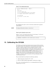
... RS232 mode 38400bps. Menu 9 and 0: Exiting the menu system Options `9' and `0' exit from the menu system. If you have Campbell Scientific's Device configuration program a terminal emulation screen is already set in RS232 mode it is recommended that typing `0' will take effect until you can be run using the optional CS120A calibrator part number 010816. If your CS120A is used to set the sensor to change will lose all changes made...
... RS232 mode 38400bps. Menu 9 and 0: Exiting the menu system Options `9' and `0' exit from the menu system. If you have Campbell Scientific's Device configuration program a terminal emulation screen is already set in RS232 mode it is recommended that typing `0' will take effect until you can be run using the optional CS120A calibrator part number 010816. If your CS120A is used to set the sensor to change will lose all changes made...
CS120A Visibility Sensor
Page 44
... the new calibration constants will be saved automatically. Once the second stage of the test will take approximately two minutes. The use an air duster to such contaminants. Saving user settings Press any key to errors in its visibility measurements may be used. Please refer to the help built into the DevConfig software for those prone to update the CS120A operating system. Calibration of...
... the new calibration constants will be saved automatically. Once the second stage of the test will take approximately two minutes. The use an air duster to such contaminants. Saving user settings Press any key to errors in its visibility measurements may be used. Please refer to the help built into the DevConfig software for those prone to update the CS120A operating system. Calibration of...
