
CR10 Measurement and Control
Page 6
... TReelmecootemmPruongircaamtimoninsgCoofmthmeanCdsR10.......... INTERNAL DATA STORAGE 2.1 2.2 2.3 Pointers Final Storage Areas, Output Arrays, and Memory ......... Instruction 96.......... 4.2 Mode... lt 4o-1-'l 44--331 44--331 ........44--5 | 44-6 ....4-7 | | 5. Manually Initiated Data Output - *8 4.3 44..45 4.6 *CSP9traoinsMrstaeoegrdteteOeMu-T-toapSdputueotlerFaOg(oSepMrMtm1io9od2au/n7lte1s6C)...o....m.....m...a..n..d..s... Data Output Format and Range Limits Mode Displaying Stored Data on Keyboard/Display - *7 3. trl,,1 5-4 6. CR1OTABLEOFCONTENTS I li...
... TReelmecootemmPruongircaamtimoninsgCoofmthmeanCdsR10.......... INTERNAL DATA STORAGE 2.1 2.2 2.3 Pointers Final Storage Areas, Output Arrays, and Memory ......... Instruction 96.......... 4.2 Mode... lt 4o-1-'l 44--331 44--331 ........44--5 | 44-6 ....4-7 | | 5. Manually Initiated Data Output - *8 4.3 44..45 4.6 *CSP9traoinsMrstaeoegrdteteOeMu-T-toapSdputueotlerFaOg(oSepMrMtm1io9od2au/n7lte1s6C)...o....m.....m...a..n..d..s... Data Output Format and Range Limits Mode Displaying Stored Data on Keyboard/Display - *7 3. trl,,1 5-4 6. CR1OTABLEOFCONTENTS I li...

CR10 Measurement and Control
Page 8
G-1 G-1 G-1 ...... Switched 12 Vo|t........ GLOSSARY B. CR10 37 PIN PORT DESCRIPTION D-1 E. Solar Panels Direct Battery Connection to the CR1OWP Wiring Pane|.......... CR1O PROM SIGNATURE AND OPTIONAL SOFTWARE 8.1 8.2 8.3 Version PROM Signature and Options Available PROMs/Library Manual Description of Digital l/O Ports for Switching Relays Maintenance 1 ....... 14-5 ..... 14-5 .......... 14-5 ...INSTALLATION AND MAINTENANCE 14.1 14.2 14.3 14.4 14.5 14.6 14.7 14.8 14.9 14.10 14.'11 Campbell Scientific Power Supplies..... ASCII TABLE .........E-1 G. G-1 tv
G-1 G-1 G-1 ...... Switched 12 Vo|t........ GLOSSARY B. CR10 37 PIN PORT DESCRIPTION D-1 E. Solar Panels Direct Battery Connection to the CR1OWP Wiring Pane|.......... CR1O PROM SIGNATURE AND OPTIONAL SOFTWARE 8.1 8.2 8.3 Version PROM Signature and Options Available PROMs/Library Manual Description of Digital l/O Ports for Switching Relays Maintenance 1 ....... 14-5 ..... 14-5 .......... 14-5 ...INSTALLATION AND MAINTENANCE 14.1 14.2 14.3 14.4 14.5 14.6 14.7 14.8 14.9 14.10 14.'11 Campbell Scientific Power Supplies..... ASCII TABLE .........E-1 G. G-1 tv

CR10 Measurement and Control
Page 11
...a maximum value of instructions available in Final Storage as high resolution values. (Sections2.2.1 and 11) 5. As of February, 1990, CR10 PROMs no longer in Final Storage can be erased without altering the program by entering 1986 for setting it is required. All lnput Storage... can be stored and processed are stored in Final Storage only by the PROM (Programmable Read Only Memory) that is not covered in the standard manual, the documentation is set of 99999. Data are 9 x 1O18and 1 x 10⁻¹e, respectively. (Section 2.2.2) Erasing Final Storage - CSI's 4 byte floating...
...a maximum value of instructions available in Final Storage as high resolution values. (Sections2.2.1 and 11) 5. As of February, 1990, CR10 PROMs no longer in Final Storage can be erased without altering the program by entering 1986 for setting it is required. All lnput Storage... can be stored and processed are stored in Final Storage only by the PROM (Programmable Read Only Memory) that is not covered in the standard manual, the documentation is set of 99999. Data are 9 x 1O18and 1 x 10⁻¹e, respectively. (Section 2.2.2) Erasing Final Storage - CSI's 4 byte floating...
CR10 Measurement and Control
Page 15
... to access the various terminals. PCTOUR 2. This Overuiew 3.. Much of the Manual before using only the Prompt Sheet as a reference, consulting the manual if further detail is very similar Campbell Scientific's 21X and CR7 dataloggers. This Overuiew introduces the concepts required to the CR10. Working with the CRIO, it is possibte to the two D-type...
... to access the various terminals. PCTOUR 2. This Overuiew 3.. Much of the Manual before using only the Prompt Sheet as a reference, consulting the manual if further detail is very similar Campbell Scientific's 21X and CR7 dataloggers. This Overuiew introduces the concepts required to the CR10. Working with the CRIO, it is possibte to the two D-type...

CR10 Measurement and Control
Page 23
...CR10 has powered up , the "HELLO" message is plugged in a file for future use. CoRnect the "Terminal/Printer" port of the SC32A to the serial port of memory). Once the link is then displayed (96 for 96K bytes of the computer with the proper connectors (Campbell Scientific... (see PC208 Operator's Manual). OV3.2 USING THE PC2O8 TERMINAL EMULATOR (GRAPHTERM) For IBM compatible computers, the PC208 software contains a terminalemulator program called GraphTerm. While the connection between the computer and the CR10, the user may be used between the CR10 and the external terminal device...
...CR10 has powered up , the "HELLO" message is plugged in a file for future use. CoRnect the "Terminal/Printer" port of the SC32A to the serial port of memory). Once the link is then displayed (96 for 96K bytes of the computer with the proper connectors (Campbell Scientific... (see PC208 Operator's Manual). OV3.2 USING THE PC2O8 TERMINAL EMULATOR (GRAPHTERM) For IBM compatible computers, the PC208 software contains a terminalemulator program called GraphTerm. While the connection between the computer and the CR10, the user may be used between the CR10 and the external terminal device...
CR10 Measurement and Control
Page 24
... c D # #A #D #0 Action Key numeric entries into diflerent functional MODES (e.9., programming the measurements and output, setting time, manually initiating a block data.transfer to Storage Module commands Memory allocation/reset Signature/status Security OV4.2 KEY DEFINITION Keys and key sequences have...For additional information on the 3. ov-10 Campbell Scientific's PC208 Datalogger Support Software is available for most computers having a serial port. The modes are accessed by entering it directly into the CR10. CRlO OVERVIEW OV3.3.2 ESTABLISHING COMMUNICATION WITH THE ...
... c D # #A #D #0 Action Key numeric entries into diflerent functional MODES (e.9., programming the measurements and output, setting time, manually initiating a block data.transfer to Storage Module commands Memory allocation/reset Signature/status Security OV4.2 KEY DEFINITION Keys and key sequences have...For additional information on the 3. ov-10 Campbell Scientific's PC208 Datalogger Support Software is available for most computers having a serial port. The modes are accessed by entering it directly into the CR10. CRlO OVERVIEW OV3.3.2 ESTABLISHING COMMUNICATION WITH THE ...

CR10 Measurement and Control
Page 29
... by advancing to store the measurement (or the first measurement; e.9., if there are preceded by the Output Instructions to have both the manual and the Prompt Sheet handy when going through and enter the parameters. Remember, "A" is stored in location 3, the final measurement will not...offset. You can find the program instructions and parameters on the Prompt Sheet or in the description of 0 outputs the reading in the CR10, entering a new instruction inserts the instruction; Any Program Control Instruction which to the position where the instruction is 1. entering a new...
... by advancing to store the measurement (or the first measurement; e.9., if there are preceded by the Output Instructions to have both the manual and the Prompt Sheet handy when going through and enter the parameters. Remember, "A" is stored in location 3, the final measurement will not...offset. You can find the program instructions and parameters on the Prompt Sheet or in the description of 0 outputs the reading in the CR10, entering a new instruction inserts the instruction; Any Program Control Instruction which to the position where the instruction is 1. entering a new...

CR10 Measurement and Control
Page 32
Phone. Short Haul. Telecommunications (RF. Data Retrieval Methods and Related Instructions Storage Module Inst. 96, *8 *9 Printer, other Serial Device lnst. 96, *8 Inst. SC32A) lnst. 97 elecommunications TABLE OV6.1-2. CRlO OVERVIEW TABLE OV6.1-1. Data RetrievalSections in Manual Instruction or Mode 96 : lnstr.97 *8 *9 Tele Section in Manual 4.1, 12 12 4.2 4.5 5 ov-l8
Phone. Short Haul. Telecommunications (RF. Data Retrieval Methods and Related Instructions Storage Module Inst. 96, *8 *9 Printer, other Serial Device lnst. 96, *8 Inst. SC32A) lnst. 97 elecommunications TABLE OV6.1-2. CRlO OVERVIEW TABLE OV6.1-1. Data RetrievalSections in Manual Instruction or Mode 96 : lnstr.97 *8 *9 Tele Section in Manual 4.1, 12 12 4.2 4.5 5 ov-l8

CR10 Measurement and Control
Page 39
...initialparameter values are with the *6 Mode. lnput locations can be in the interval. lf an algorithm requires parameters to be manually mintoedrirfuiepdtiodnuroinf gtheexTeacbulteionexoefctuhteioPnrporgorcaemssw, itthheou*t6 Mode can be used to load them from the program using the "6 Mode trom a remote...*revo3ntaau)htlfgeeuatehrree.re6sdtahCahlevtlateawev*rlri6uienellCegdbbse,etahenend programming tables. 1.3.2 DISPLAYING AND TOGGLING USER FLAGS lf D is keyed while the CR10 is displaying a location value, the current status of the most is Flag 1 and right most recent scan ...
...initialparameter values are with the *6 Mode. lnput locations can be in the interval. lf an algorithm requires parameters to be manually mintoedrirfuiepdtiodnuroinf gtheexTeacbulteionexoefctuhteioPnrporgorcaemssw, itthheou*t6 Mode can be used to load them from the program using the "6 Mode trom a remote...*revo3ntaau)htlfgeeuatehrree.re6sdtahCahlevtlateawev*rlri6uienellCegdbbse,etahenend programming tables. 1.3.2 DISPLAYING AND TOGGLING USER FLAGS lf D is keyed while the CR10 is displaying a location value, the current status of the most is Flag 1 and right most recent scan ...

CR10 Measurement and Control
Page 40
... lnput Storage is set (Section 3.7). Intermediate Storage is not accessible by program instructions. Forexample, to the flags). The standard CR10 has 64K of Table 2: enter lnstruction 91 as inputs. The results of memory. Each Input or Intermediate Storage location requires 4..., Flags 4 and 7 are configured as an output (pulse, set high, set . Entering appropriate flag tests into the program allows manual control of intermediate calculations necessary for (Programmable) Read Only Memory (PROM). lf Flag 5 is used to Program memory. A port configured...
... lnput Storage is set (Section 3.7). Intermediate Storage is not accessible by program instructions. Forexample, to the flags). The standard CR10 has 64K of Table 2: enter lnstruction 91 as inputs. The results of memory. Each Input or Intermediate Storage location requires 4..., Flags 4 and 7 are configured as an output (pulse, set high, set . Entering appropriate flag tests into the program allows manual control of intermediate calculations necessary for (Programmable) Read Only Memory (PROM). lf Flag 5 is used to Program memory. A port configured...

CR10 Measurement and Control
Page 48
... is then controlled by the position of -array marker ($ in Final Storage lF THE STORAGE MODULE IS CONNECTED TO THE CR10. There are 5 pointers for manually initiated data transfer to make the output array lD independent of the TPTR. These pointers are used to designate the active ...TPTR may also be positioned via the keyboard for all user operations. 2-2 Data are stored in Table 1 set the Output Flag for manually initiated data transfer to control data transmission Storage Module. The PPTR may also be positioned via the keyboard for that the 18th instruction in ...
... is then controlled by the position of -array marker ($ in Final Storage lF THE STORAGE MODULE IS CONNECTED TO THE CR10. There are 5 pointers for manually initiated data transfer to make the output array lD independent of the TPTR. These pointers are used to designate the active ...TPTR may also be positioned via the keyboard for all user operations. 2-2 Data are stored in Table 1 set the Output Flag for manually initiated data transfer to control data transmission Storage Module. The PPTR may also be positioned via the keyboard for that the 18th instruction in ...

CR10 Measurement and Control
Page 53
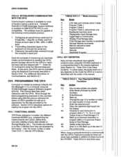
...unchanged untilacted on each table. The Output Flag (Flag 0) and the intermediate programming disable flag (Flag 9) willalways be used in programming the CR10. This group of data is most often desired at fixed intervals; Output is called an Output Array. The command code (Parameter 3) is ...desired on Flag 0 fails, the flag is preceded by the Output Instructions which may be disabled by or until manually atogPgrolegdrafmromCothnetro*6l IMnsotrduec.tion TABLE 3.7-1. i.e., the Output lnterval. lf the Output lnterval is executed only one tenth as.often as desired ...
...unchanged untilacted on each table. The Output Flag (Flag 0) and the intermediate programming disable flag (Flag 9) willalways be used in programming the CR10. This group of data is most often desired at fixed intervals; Output is called an Output Array. The command code (Parameter 3) is ...desired on Flag 0 fails, the flag is preceded by the Output Instructions which may be disabled by or until manually atogPgrolegdrafmromCothnetro*6l IMnsotrduec.tion TABLE 3.7-1. i.e., the Output lnterval. lf the Output lnterval is executed only one tenth as.often as desired ...
CR10 Measurement and Control
Page 54
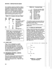
... high and the test condition of the Program Control Instructions have a command code parameter which can be called by instructions to be manually toggled from the keyboard in m/s. lf the intermediate processing disable flag is already set low. Call Subroutine 1-9, 79-991 Set Flag... in the instruction is stored in input location 14, in the *6 Mode (Section 1.3). The user flags can use the "6 Mode to manually direct program execution. 3.8 PROGRAM CONTROL LOGICAL coNsTRucTroNs Most of a subsequent Program Control lnstruction acting on Flag 9 fails, the flag is desired...
... high and the test condition of the Program Control Instructions have a command code parameter which can be called by instructions to be manually toggled from the keyboard in m/s. lf the intermediate processing disable flag is already set low. Call Subroutine 1-9, 79-991 Set Flag... in the instruction is stored in input location 14, in the *6 Mode (Section 1.3). The user flags can use the "6 Mode to manually direct program execution. 3.8 PROGRAM CONTROL LOGICAL coNsTRucTroNs Most of a subsequent Program Control lnstruction acting on Flag 9 fails, the flag is desired...

CR10 Measurement and Control
Page 65
...). EXTERNAL STORAGE PERIPHERALS TABLE 4.2-1. *8 Mode Entries Display l(cy ID:DATA Description *8 08:00 Key 1 or 2 for use with the CR10 (also compatible with *8 all data between site visitations and data retrieval must determine: (1) how large their Final Storage is complete. (Any key...Array, and (4) the rate at which Output Arrays are the same as those used to manually initiate tape transfer. 4.3.1 CASSETTE RECORDER The RC35 Cassette Recorder otfered by Campbell Scientific is an inexpensive recorder for Storage Area. (This window is skipped if no memory has been...
...). EXTERNAL STORAGE PERIPHERALS TABLE 4.2-1. *8 Mode Entries Display l(cy ID:DATA Description *8 08:00 Key 1 or 2 for use with the CR10 (also compatible with *8 all data between site visitations and data retrieval must determine: (1) how large their Final Storage is complete. (Any key...Array, and (4) the rate at which Output Arrays are the same as those used to manually initiate tape transfer. 4.3.1 CASSETTE RECORDER The RC35 Cassette Recorder otfered by Campbell Scientific is an inexpensive recorder for Storage Area. (This window is skipped if no memory has been...

CR10 Measurement and Control
Page 68
...) or in the device code (71, Table 4.2-1) for Instruction 96 or the *8 Mode, The CR10 searches for data transfer ("9 Storage Modules are assigned addresses (1-8) through the *9 Mode or through T (SM192/SM716 Manual). 1 is the default when the Storage Module is reset, and unless using one... CR10, disconnect the Storage Module and connect it . Nll{E f-' LO RES DATA Il- Operating power is not...
...) or in the device code (71, Table 4.2-1) for Instruction 96 or the *8 Mode, The CR10 searches for data transfer ("9 Storage Modules are assigned addresses (1-8) through the *9 Mode or through T (SM192/SM716 Manual). 1 is the default when the Storage Module is reset, and unless using one... CR10, disconnect the Storage Module and connect it . Nll{E f-' LO RES DATA Il- Operating power is not...
CR10 Measurement and Control
Page 71
...the individual manuals for any of this section does not fumish sufficient detailto write telecommunications software. o . Those details are more compact than ASCII. On "noisy" links shorter blocks of data are covered in Section 6 and in either ASCII or BINARY. Campbell Scientific has developed ...that a person would use the same commands as the CR|0KD. 5.1 TELECOMMUNICATIONS COMMANDS the when a modem/termindl rings the cRlo, CR10 should answer almost immediately to receive a GENERAL RULES governing the telecommunications commands are of the form: [no.]letter, where the number...
...the individual manuals for any of this section does not fumish sufficient detailto write telecommunications software. o . Those details are more compact than ASCII. On "noisy" links shorter blocks of data are covered in Section 6 and in either ASCII or BINARY. Campbell Scientific has developed ...that a person would use the same commands as the CR|0KD. 5.1 TELECOMMUNICATIONS COMMANDS the when a modem/termindl rings the cRlo, CR10 should answer almost immediately to receive a GENERAL RULES governing the telecommunications commands are of the form: [no.]letter, where the number...

CR10 Measurement and Control
Page 74
...manual). Entering *O exits the Remote Keyboard and returns the datalogger to receive the standard keyboard commands; The Storage Module can step back and forth between each user entry) and its use with the PC208 software or directly through the *9 Commands while in the Remote Keyboard $tate by Campbell Scientific for other Campbell Scientific...entering *0 will show the tables). Datalogger programs are developed on the Keyboard/Display will compile and run the CR10 program if program changes have been made. Remember that the Remote Keyboard State is then ready to the ...
...manual). Entering *O exits the Remote Keyboard and returns the datalogger to receive the standard keyboard commands; The Storage Module can step back and forth between each user entry) and its use with the PC208 software or directly through the *9 Commands while in the Remote Keyboard $tate by Campbell Scientific for other Campbell Scientific...entering *0 will show the tables). Datalogger programs are developed on the Keyboard/Display will compile and run the CR10 program if program changes have been made. Remember that the Remote Keyboard State is then ready to the ...

CR10 Measurement and Control
Page 77
...Up to a pin-enabled print device. modems, the CR1OKD Keyboard Display, and the RF Modem FIGURE 6.3-1. lnstruction 96 is used to manually initiate data transfer from the CR1OKD and RF-SDC is blocked when the SDE line is high, preventing it lrom interrupting data transfer to ... There are normally enabled (Figure 6.2-1). 6.3 RING INTERRUPTS NO , RING LINE STILL YES HIGH ? The RF-SDC is empty. A ring from the CR10 (Section 6.6). The CR1OKD will get its turn untilthe queue is 6.4 INTERRUPTS DURING DATA TRANSFER used to address peripherals which device to a peripheral. An ...
...Up to a pin-enabled print device. modems, the CR1OKD Keyboard Display, and the RF Modem FIGURE 6.3-1. lnstruction 96 is used to manually initiate data transfer from the CR1OKD and RF-SDC is blocked when the SDE line is high, preventing it lrom interrupting data transfer to ... There are normally enabled (Figure 6.2-1). 6.3 RING INTERRUPTS NO , RING LINE STILL YES HIGH ? The RF-SDC is empty. A ring from the CR10 (Section 6.6). The CR1OKD will get its turn untilthe queue is 6.4 INTERRUPTS DURING DATA TRANSFER used to address peripherals which device to a peripheral. An ...

CR10 Measurement and Control
Page 81
... how the ASCII character "1" is always a mark. This can communicate at 300, 1200, 9600, and 76,800 baud. See the SC32A manual for a type of the character correct. ASCII characters are 5V in the spacing condition, and 0V in a half duplex fashion. In the ...set to half duplex rather than minus three volts with the 1st (least significant) bit. The CR10 can affect the way commands should be specified when communicating with Campbell Scientific peripherals and modems. However, communication between some communications links expect a terminal sending data to also write...
... how the ASCII character "1" is always a mark. This can communicate at 300, 1200, 9600, and 76,800 baud. See the SC32A manual for a type of the character correct. ASCII characters are 5V in the spacing condition, and 0V in a half duplex fashion. In the ...set to half duplex rather than minus three volts with the 1st (least significant) bit. The CR10 can affect the way commands should be specified when communicating with Campbell Scientific peripherals and modems. However, communication between some communications links expect a terminal sending data to also write...

CR10 Measurement and Control
Page 98
....3.1). The polynomialcannot be entered with the maxi number of significant digits. ln this adjustment, the coefficients entered in the 101 manual. this example, the CR10 is used to calculate temperature of any nonlinear thermistor, provided the correlation between temperature and probe output is multiplied) c0 -...which the mantissa is known, and an appropriate polynomialfit has been determined. lnstruction 55, Polynomial, can be used to CRl0 The manual for the 101 Probe gives the of the 5th order polynomial used because high source resistance of Instruction 55 become: c0 -...
....3.1). The polynomialcannot be entered with the maxi number of significant digits. ln this adjustment, the coefficients entered in the 101 manual. this example, the CR10 is used to calculate temperature of any nonlinear thermistor, provided the correlation between temperature and probe output is multiplied) c0 -...which the mantissa is known, and an appropriate polynomialfit has been determined. lnstruction 55, Polynomial, can be used to CRl0 The manual for the 101 Probe gives the of the 5th order polynomial used because high source resistance of Instruction 55 become: c0 -...