
CR10 Measurement and Control
Page 6
... Numbers 33-1-11 Indexing Input Locations and Ports.......... | 3-11 Voltage Range and Overrange Detection [ 3--221 Output Processing. 3-2ll Use of Flags: Output and Program Control....... ...........33--33ll Program Control LogicalConstructions 3-4ll Instruction Memory and Execution Time...... 3-5 Error Codes .......... 3-8 DATA R ETRI EVAUCOM M U NICATIO N "'ll 4. INSTRUCTION SET BASICS I tI l I 2. TELECOMMUNICATIONS 5.1 5.2 TReelmecootemmPruongircaamtimoninsgCoofmthmeanCdsR10.......... Instruction 96.......... 4.2 Mode... Manually Initiated Data Output...
... Numbers 33-1-11 Indexing Input Locations and Ports.......... | 3-11 Voltage Range and Overrange Detection [ 3--221 Output Processing. 3-2ll Use of Flags: Output and Program Control....... ...........33--33ll Program Control LogicalConstructions 3-4ll Instruction Memory and Execution Time...... 3-5 Error Codes .......... 3-8 DATA R ETRI EVAUCOM M U NICATIO N "'ll 4. INSTRUCTION SET BASICS I tI l I 2. TELECOMMUNICATIONS 5.1 5.2 TReelmecootemmPruongircaamtimoninsgCoofmthmeanCdsR10.......... Instruction 96.......... 4.2 Mode... Manually Initiated Data Output...
CR10 Measurement and Control
Page 15
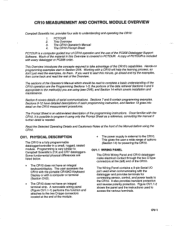
... very similar Campbell Scientific's 21X and CR7 dataloggers. Programming is included with every datalogger or PC208 order. The CR10 does not have detailed descriptions of the CR|0's capabilities. This gives the user a wide range of serialcommunications. The Wiring Panelcontains a 9-pin Serial l/O port used to take advantage of each programming instruction, and Section 13 goes into detailon the CRl0 measurement procedures. ov-1 The CR10 Operator's Manual 4. This...
... very similar Campbell Scientific's 21X and CR7 dataloggers. Programming is included with every datalogger or PC208 order. The CR10 does not have detailed descriptions of the CR|0's capabilities. This gives the user a wide range of serialcommunications. The Wiring Panelcontains a 9-pin Serial l/O port used to take advantage of each programming instruction, and Section 13 goes into detailon the CRl0 measurement procedures. ov-1 The CR10 Operator's Manual 4. This...

CR10 Measurement and Control
Page 18
... CR10 analog ground (AG). A port can be used as an independent channel to measure voltage with respect to the differentialchannels 1 through CB are single-ended channels 1 and 2; Configured as input ports, commonly used to the voltqge on /otf control of ditferential channef 1 are digital lnput/Output ports. In a differential measurement, the voltage on older wiring panels). the H and L sides of an external signal. OVl.1.2 SWITCHED EXCITATION OUTPUTS...
... CR10 analog ground (AG). A port can be used as an independent channel to measure voltage with respect to the differentialchannels 1 through CB are single-ended channels 1 and 2; Configured as input ports, commonly used to the voltqge on /otf control of ditferential channef 1 are digital lnput/Output ports. In a differential measurement, the voltage on older wiring panels). the H and L sides of an external signal. OVl.1.2 SWITCHED EXCITATION OUTPUTS...

CR10 Measurement and Control
Page 20
... entries specify: (1) the measurement type (2) the number of channels to measure (3) the input voltage range (a) the Input Storage Location (5) the sensor calibration constants used to convert the sensor output to engineering units l/O lnstructions also control analog INPUT STORAGE Holds the results of a sensor signal to external devices (Figure OV5.1-1). Arithmetic, lranscendental OUTPUT PROCESS'NG INSTRUCTIONS Perform calculations over each time a new measurement or P ROCESS I NG I NSTR U CTI...
... entries specify: (1) the measurement type (2) the number of channels to measure (3) the input voltage range (a) the Input Storage Location (5) the sensor calibration constants used to convert the sensor output to engineering units l/O lnstructions also control analog INPUT STORAGE Holds the results of a sensor signal to external devices (Figure OV5.1-1). Arithmetic, lranscendental OUTPUT PROCESS'NG INSTRUCTIONS Perform calculations over each time a new measurement or P ROCESS I NG I NSTR U CTI...
CR10 Measurement and Control
Page 24
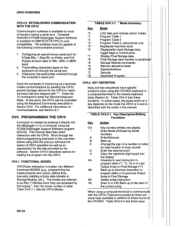
... manual. TABLE OV4.1-1. * Mode Summary Key *0 *1 *2 *3 - *5:- *6 *7 *8 *9 *A -*B *c " trD, Mode LOG data and indicate active Tables Program Table 1 Program Table 2 Program Table 3, subroutines only Display/set real time clock Display/alter Input Storage data, toggle flags or control ports. CRlO OVERVIEW OV3.3.2 ESTABLISHING COMMUNICATION WITH THE CR1O Communication software is available for IBM PC|XTIAT/PS-2's and compatibles, The software must be controlled using the Keyboard Commands described in Section OV4. Campbell Scientific's PC208 Datalogger Support Software...
... manual. TABLE OV4.1-1. * Mode Summary Key *0 *1 *2 *3 - *5:- *6 *7 *8 *9 *A -*B *c " trD, Mode LOG data and indicate active Tables Program Table 1 Program Table 2 Program Table 3, subroutines only Display/set real time clock Display/alter Input Storage data, toggle flags or control ports. CRlO OVERVIEW OV3.3.2 ESTABLISHING COMMUNICATION WITH THE CR1O Communication software is available for IBM PC|XTIAT/PS-2's and compatibles, The software must be controlled using the Keyboard Commands described in Section OV4. Campbell Scientific's PC208 Datalogger Support Software...

CR10 Measurement and Control
Page 45
... (i.e., the information for Mode 3 could be followed are 4 two-character control codes which must be and reset the sent to the datalogger. 1-9 After the operation is finished "13:0000" is not connected or the wrong address was given. "S" is connected. The command to for the lowest address Storage Module that could be used when a program is received, the CR10 buffers the data in...
... (i.e., the information for Mode 3 could be followed are 4 two-character control codes which must be and reset the sent to the datalogger. 1-9 After the operation is finished "13:0000" is not connected or the wrong address was given. "S" is connected. The command to for the lowest address Storage Module that could be used when a program is received, the CR10 buffers the data in...

CR10 Measurement and Control
Page 49
... the seventh digit. High 0.0000 +.00001 +99999. 2.2.2 INPUT AND INTERMEDIATE STORAGE DATA FORMAT While output data have allocated memory to the DSP location when the datalogger compiles a program. Until the ring memory wraps around and dreactaovoevreerdwruitseingoctchuerst,8thMeoddaet.aTmhiasy be less than 1 in the CR10 are set to Final Storage Area2, the display willshow: The resolution of +6999. Resolution Range Limits...
... the seventh digit. High 0.0000 +.00001 +99999. 2.2.2 INPUT AND INTERMEDIATE STORAGE DATA FORMAT While output data have allocated memory to the DSP location when the datalogger compiles a program. Until the ring memory wraps around and dreactaovoevreerdwruitseingoctchuerst,8thMeoddaet.aTmhiasy be less than 1 in the CR10 are set to Final Storage Area2, the display willshow: The resolution of +6999. Resolution Range Limits...
CR10 Measurement and Control
Page 54
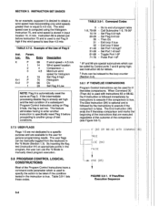
... enter another instruction to specifically reset Flag 9 before Instruction 75 and is used with Instructions 83 or 88-92, the lf Instruction is stored in input location 14, in the *6 Mode (Section 1.3). Table 3.8-1 lists these codes. Call Subroutine 1-9, 79-991 Set Flag 0-9 high Set Flag 0-9low Then Do Exit loop if true Exit loop if false Set Port 1-8 nignz Set Port 1-8low2 Toggle Port 1-82 Pulse Port 1-82 1 97...
... enter another instruction to specifically reset Flag 9 before Instruction 75 and is used with Instructions 83 or 88-92, the lf Instruction is stored in input location 14, in the *6 Mode (Section 1.3). Table 3.8-1 lists these codes. Call Subroutine 1-9, 79-991 Set Flag 0-9 high Set Flag 0-9low Then Do Exit loop if true Exit loop if false Set Port 1-8 nignz Set Port 1-8low2 Toggle Port 1-82 Pulse Port 1-82 1 97...
CR10 Measurement and Control
Page 58
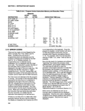
Program Gontrol Instruction Memory and Execution Times INSTRUCTION 83 IF CASE SECTION 3. INSTRUCTION SET BASICS TABLE 3.9-4.
Program Gontrol Instruction Memory and Execution Times INSTRUCTION 83 IF CASE SECTION 3. INSTRUCTION SET BASICS TABLE 3.9-4.
CR10 Measurement and Control
Page 66
VOLUME CONTROL When recording data, the RC35's volume setting does not matter. New tapes are not recommended. Two are plugged into the POWER and MIC jacks on tape CANNOT be overcome by CRl0 through SC92A or SC93A);4 M size batteries; 12OVAC/6 VDC adapter Drain Current 200 mA typ./S sec., while Recording 300 max. Additionalcircuitry shapes the data signalwaveform. The SC235 CR21 Cassette Connector Interface supplied with the CR21 datalogger is...
VOLUME CONTROL When recording data, the RC35's volume setting does not matter. New tapes are not recommended. Two are plugged into the POWER and MIC jacks on tape CANNOT be overcome by CRl0 through SC92A or SC93A);4 M size batteries; 12OVAC/6 VDC adapter Drain Current 200 mA typ./S sec., while Recording 300 max. Additionalcircuitry shapes the data signalwaveform. The SC235 CR21 Cassette Connector Interface supplied with the CR21 datalogger is...

CR10 Measurement and Control
Page 67
... transferred to output the date and time values. lf the last data point in a full line is high resolution, it is past the recording head. (lnternal batteries or AC power required.) 2. lf the Start of dump location is equalto the End of dump location, the CR10 willwrite a "dummy" block of the wiring panel. (Via the SC12 ribbon cable if using *8 with...
... transferred to output the date and time values. lf the last data point in a full line is high resolution, it is past the recording head. (lnternal batteries or AC power required.) 2. lf the Start of dump location is equalto the End of dump location, the CR10 willwrite a "dummy" block of the wiring panel. (Via the SC12 ribbon cable if using *8 with...

CR10 Measurement and Control
Page 74
... indicate active tables (keying "*0" on the computer using the program editor (EDLOG) and downloaded to the K command, the CR1 sends datalogger time, user flag status, the data at to receive the standard keyboard commands; It is sent after each entry. CRl0 sends security level (0-3) and checksum: Sxx Cxxxx tXlM Connect to remember that entering *0 will just display "LOG" when *0 is...
... indicate active tables (keying "*0" on the computer using the program editor (EDLOG) and downloaded to the K command, the CR1 sends datalogger time, user flag status, the data at to receive the standard keyboard commands; It is sent after each entry. CRl0 sends security level (0-3) and checksum: Sxx Cxxxx tXlM Connect to remember that entering *0 will just display "LOG" when *0 is...
CR10 Measurement and Control
Page 89
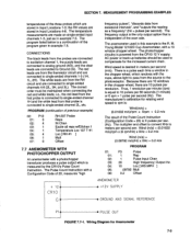
... Model 121O2D Cup Anemometer, with a Configuration Code of the program given in the chopper wheel, there are connected to single-ended channel2L, etc. SECTION 7. MEASUREMENT PROGRAMMING EXAMPLES temperatures of the three probes which is a continuation of 20, measures "high +12 CR1 O \, frequency pulses", "discards data from the CR10 12 V supply; M. AC power or back-up batteries should be maintained when connecting the red...
... Model 121O2D Cup Anemometer, with a Configuration Code of the program given in the chopper wheel, there are connected to single-ended channel2L, etc. SECTION 7. MEASUREMENT PROGRAMMING EXAMPLES temperatures of the three probes which is a continuation of 20, measures "high +12 CR1 O \, frequency pulses", "discards data from the CR10 12 V supply; M. AC power or back-up batteries should be maintained when connecting the red...
CR10 Measurement and Control
Page 115
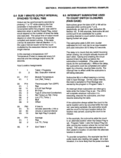
... TIME Output can interrupt a table while the Output Flag is then added to seconds by the execution interval, but some longer interual. lf the table overran its execution interval (Section 1.1.1), the output intervalwould not be executed when control Ports 7 or 8, respectively, go high (5 V, see Instruction 85, Section 12). The CR10 willcomplete whatever instruction it is more likely that any switch...
... TIME Output can interrupt a table while the Output Flag is then added to seconds by the execution interval, but some longer interual. lf the table overran its execution interval (Section 1.1.1), the output intervalwould not be executed when control Ports 7 or 8, respectively, go high (5 V, see Instruction 85, Section 12). The CR10 willcomplete whatever instruction it is more likely that any switch...
CR10 Measurement and Control
Page 189
... that the coefficients are indicated by calculating new coefficients. Each time Instruction 24 is executed a new set . Calibratlon at that contains Instruction 24. To prevent overrun errors which must be used , Instruction 24 could easily change 50 degrees. Instruction 24 calibration, as opposed to complete. lf the measurements are replaced each time that the program table is executed. Calibration coefficients are being averaged, the effect of...
... that the coefficients are indicated by calculating new coefficients. Each time Instruction 24 is executed a new set . Calibratlon at that contains Instruction 24. To prevent overrun errors which must be used , Instruction 24 could easily change 50 degrees. Instruction 24 calibration, as opposed to complete. lf the measurements are replaced each time that the program table is executed. Calibration coefficients are being averaged, the effect of...

CR10 Measurement and Control
Page 194
SECTION 14. INSTALLATION AND MAINTENANCE System operating time for the batteries can be determined by dividing the battery capacity (amp-hours) by the average system current drain. The CR10 draws
SECTION 14. INSTALLATION AND MAINTENANCE System operating time for the batteries can be determined by dividing the battery capacity (amp-hours) by the average system current drain. The CR10 draws

CR10 Measurement and Control
Page 196
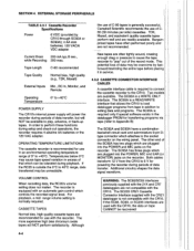
.... A sustained input voltage in applications requiring intrinsically safe equipment. 2. External power sources must be inserted into either of the CHG ports, polarity doesn't matter. However, if the batteries are at the 12 V port, not the voltage of the PS512M is the internal lead acid battery. Campbell Scientific makes the following recommendations: 1. The switch turns power on when a charging source is needed to the...
.... A sustained input voltage in applications requiring intrinsically safe equipment. 2. External power sources must be inserted into either of the CHG ports, polarity doesn't matter. However, if the batteries are at the 12 V port, not the voltage of the PS512M is the internal lead acid battery. Campbell Scientific makes the following recommendations: 1. The switch turns power on when a charging source is needed to the...
CR10 Measurement and Control
Page 206
... receiving output over pin 6 (the PE line) in this category. The instruction location number gives the location of data to set by the user, usually with CR10 Program lnstructions, parameters are entered to specify exactly what a given instruction is set . Output occurs only when the Output Flag (Flag 0) is to certain conditions (Sections OV4 and 1.2.1). OUTPUT PROCESSING INSTRUCTIONS: Process data values and generate Output Arrays. MANUALLY INITIATED: Initiated by a Program Control Instruction...
... receiving output over pin 6 (the PE line) in this category. The instruction location number gives the location of data to set by the user, usually with CR10 Program lnstructions, parameters are entered to specify exactly what a given instruction is set . Output occurs only when the Output Flag (Flag 0) is to certain conditions (Sections OV4 and 1.2.1). OUTPUT PROCESSING INSTRUCTIONS: Process data values and generate Output Arrays. MANUALLY INITIATED: Initiated by a Program Control Instruction...
CR10 Measurement and Control
Page 230
... 21 9-2 Programming example 7-2 Direct battery connection 14-5 Display Pointer (DPTR) 2-2 Display, See CR1OKD Keyboard/Display Displaying/Altering Input Memory, Flags and Ports-"6 Mode 1-3 Divide XY - flnstruction 3] 9-1 Setting to 16 bit accumulator 9-2 CR10 Pin Port description D-l CR1OKD Keyboard Display and SC12 cable OV-9 Displaying Stored Data (.7 Mode) 2-3 Entering programs with OV-l2 Key Definition OV-10 Typical Current Drain 14-1 Wiring Panel Connecting to the CR10 OV-3, OV-s Control Port Expansion Module with SC32A OV-g,6-5 Connecting Power to vehicle power supply 14...
... 21 9-2 Programming example 7-2 Direct battery connection 14-5 Display Pointer (DPTR) 2-2 Display, See CR1OKD Keyboard/Display Displaying/Altering Input Memory, Flags and Ports-"6 Mode 1-3 Divide XY - flnstruction 3] 9-1 Setting to 16 bit accumulator 9-2 CR10 Pin Port description D-l CR1OKD Keyboard Display and SC12 cable OV-9 Displaying Stored Data (.7 Mode) 2-3 Entering programs with OV-l2 Key Definition OV-10 Typical Current Drain 14-1 Wiring Panel Connecting to the CR10 OV-3, OV-s Control Port Expansion Module with SC32A OV-g,6-5 Connecting Power to vehicle power supply 14...
CR10 Measurement and Control
Page 234
..., Using digital l/O ports for switching Remote Keyboard State OV-9,5-4 Repetitions parameter 3-1 Resetting CR10 vi, 1-5 Resistance measu rements Bridge resistance 13-17 Requiring AC excitation 13-21 Resolution 2-3, 11-5 Retrieval options, Data storage and OV-19 RH (207) 7-4,9-6 Ring interrupts 6-3 Ring Line (Pin 3) 6-1 Ring memory 2-1 Run Time errors 3-9 s Sample - flnstruction 70] 11-3 Programming example OV-13 Sample on power-up 1-4, G-l Installing new chips G-1 Installing new PROM G-l RC35 Cassette Recorder...
..., Using digital l/O ports for switching Remote Keyboard State OV-9,5-4 Repetitions parameter 3-1 Resetting CR10 vi, 1-5 Resistance measu rements Bridge resistance 13-17 Requiring AC excitation 13-21 Resolution 2-3, 11-5 Retrieval options, Data storage and OV-19 RH (207) 7-4,9-6 Ring interrupts 6-3 Ring Line (Pin 3) 6-1 Ring memory 2-1 Run Time errors 3-9 s Sample - flnstruction 70] 11-3 Programming example OV-13 Sample on power-up 1-4, G-l Installing new chips G-1 Installing new PROM G-l RC35 Cassette Recorder...
