
Master Command Reference
Page 4
... with a concurrent printing error such as end of print data for USB connection 45 Appendix A: USB Specifications 46 Appendix B: Introducing the Brother Developer Center 47 - Print Data 5 2.1 Print data overview 5 2.2 Sample (analyzing the print data of the test page 7 2.2.1 Preparation... ...7 2.2.2 Checking the print data 7 2.2.3 Explanation of tape 42 5.6 Buffered printing normal flow for USB connection 43 5.7 Buffered printing error flow for USB connection 44 5.8 Buffered printing cooling flow ...
... with a concurrent printing error such as end of print data for USB connection 45 Appendix A: USB Specifications 46 Appendix B: Introducing the Brother Developer Center 47 - Print Data 5 2.1 Print data overview 5 2.2 Sample (analyzing the print data of the test page 7 2.2.1 Preparation... ...7 2.2.2 Checking the print data 7 2.2.3 Explanation of tape 42 5.6 Buffered printing normal flow for USB connection 43 5.7 Buffered printing error flow for USB connection 44 5.8 Buffered printing cooling flow ...

Master Command Reference
Page 9
... 180 dpi model: 1Bh, 69h, 64h, 0Eh, 00h 6 Select compression mode Selects the compression mode for each page. For 2 mm margins on 24-mm-wide tape with the 180 dpi model: 1Bh, 69h, 7Ah, 84h, 00h, 18h, 00h, 9Ch, 02h, 00h, 00h, 00h, 00h 3 Various mode settings When auto cut is...
... 180 dpi model: 1Bh, 69h, 64h, 0Eh, 00h 6 Select compression mode Selects the compression mode for each page. For 2 mm margins on 24-mm-wide tape with the 180 dpi model: 1Bh, 69h, 7Ah, 84h, 00h, 18h, 00h, 9Ch, 02h, 00h, 00h, 00h, 00h 3 Various mode settings When auto cut is...

Master Command Reference
Page 15
... command mode The printer is switched to "4. Send this command before sending raster data to the printer. 4 Job ID setting commands Internal specification commands Since this is a command for outputting with the commercial version driver, it is unnecessary for the user to send this ...this case, "no chain printing" is enabled. 8 Specify margin amount Specifies the amount of the margins. This is the command for "24 mm" tape. 6 Various mode settings This is a command for specifying a mode. (1Bh+69h+4Dh+00H) Here, nothing is specified. 16 Advanced mode settings ...
... command mode The printer is switched to "4. Send this command before sending raster data to the printer. 4 Job ID setting commands Internal specification commands Since this is a command for outputting with the commercial version driver, it is unnecessary for the user to send this ...this case, "no chain printing" is enabled. 8 Specify margin amount Specifies the amount of the margins. This is the command for "24 mm" tape. 6 Various mode settings This is a command for specifying a mode. (1Bh+69h+4Dh+00H) Here, nothing is specified. 16 Advanced mode settings ...

Master Command Reference
Page 18
... Command Reference 6 5 1 3 2 4 Print area Feeding direction Landscape Number 1 Width 3 Print area width (maximum printing width) 5 Width offset 2 Length 4 Print area length 6 Length offset TZe tape ID Tape Size Designation 1 263 3.5 mm 3.5 mm 0.13" 3.40 mm 24 dots 257 6 mm 6 mm 0.23" 5.90 mm 42 dots 258 9 mm 9 mm 0.35" 9.00mm 64 dots...
... Command Reference 6 5 1 3 2 4 Print area Feeding direction Landscape Number 1 Width 3 Print area width (maximum printing width) 5 Width offset 2 Length 4 Print area length 6 Length offset TZe tape ID Tape Size Designation 1 263 3.5 mm 3.5 mm 0.13" 3.40 mm 24 dots 257 6 mm 6 mm 0.23" 5.90 mm 42 dots 258 9 mm 9 mm 0.35" 9.00mm 64 dots...

Master Command Reference
Page 19
Raster Command Reference Heat-Shrink Tube ID Tape Size Designation 1 415 6 mm HS 5.8mm HS 0.23" 5.60 mm 40 dots 416 9 mm HS 8.8mm 0.34" 8.70mm 62 dots 417 12 mm HS 11....
Raster Command Reference Heat-Shrink Tube ID Tape Size Designation 1 415 6 mm HS 5.8mm HS 0.23" 5.60 mm 40 dots 416 9 mm HS 8.8mm 0.34" 8.70mm 62 dots 417 12 mm HS 11....

Master Command Reference
Page 20
... 3 Print area width (maximum printing width) 5 Width offset 7Overall width ID Tape Size Designation 1 3 2 Length 4 Print area length 6 Length offset 8 Width of overall print area 5 7 8 [3]×Split number+[5] [3]×Split ×2 number 279 12 mm 12 ...
... 3 Print area width (maximum printing width) 5 Width offset 7Overall width ID Tape Size Designation 1 3 2 Length 4 Print area length 6 Length offset 8 Width of overall print area 5 7 8 [3]×Split number+[5] [3]×Split ×2 number 279 12 mm 12 ...

Master Command Reference
Page 22
...fed out is 24.5 mm or less. - 18 - 2. Print Data In other words, the print data will be the 24.5 mm of tape shown below . 180dpi×180dpi TZe tape Type Minimum length Normal 4.4mm 0.18" 31 dots Maximum length 1000 mm 39.37" 7086dots Heat-Shrink Tube Type Minimum length Maximum...minimum print data length: 2 mm margins × 2 + minimum print area) is based on 24.5 mm of tape that can be on the machine specifications (due to the machine cutter position), and the minimum length of tape when the print data length is 24.5 mm. For example, even when the minimum print data...
...fed out is 24.5 mm or less. - 18 - 2. Print Data In other words, the print data will be the 24.5 mm of tape shown below . 180dpi×180dpi TZe tape Type Minimum length Normal 4.4mm 0.18" 31 dots Maximum length 1000 mm 39.37" 7086dots Heat-Shrink Tube Type Minimum length Maximum...minimum print data length: 2 mm margins × 2 + minimum print area) is based on 24.5 mm of tape that can be on the machine specifications (due to the machine cutter position), and the minimum length of tape when the print data length is 24.5 mm. For example, even when the minimum print data...

Master Command Reference
Page 23
... 1 RasterLine 3 RasterLine 2 RasterLine 1 Feeding direction Print area Print head The following shows the relationship between the raster graphics parameters and the pixels. On the actual tape, margins (feed) are converted with "various mode settings" at the beginning and the end. Raster Command Reference 2.3.5 Raster line As shown below, the parts with...
... 1 RasterLine 3 RasterLine 2 RasterLine 1 Feeding direction Print area Print head The following shows the relationship between the raster graphics parameters and the pixels. On the actual tape, margins (feed) are converted with "various mode settings" at the beginning and the end. Raster Command Reference 2.3.5 Raster line As shown below, the parts with...

Master Command Reference
Page 24
... number of pins: PT-H500/P700/E500 128pin Number of pins for right margin Raster line First byte Left and right margins Number of print area pins Total number of pins Print area Last byte 0 pin Number of pins for left margin Pins on print head Feeding direction TZe tape: Tape Type 3.5 mm...
... number of pins: PT-H500/P700/E500 128pin Number of pins for right margin Raster line First byte Left and right margins Number of print area pins Total number of pins Print area Last byte 0 pin Number of pins for left margin Pins on print head Feeding direction TZe tape: Tape Type 3.5 mm...

Master Command Reference
Page 25
Raster Command Reference Heat-Shrink Tube: Tape Type 6 mm 9 mm 12 mm 18 mm 24 mm Number of pins for left margin 50 40 31 11 0 Number of print area pins 28 48 66 106 128 Number of pins Number of bytes for raster for right margin graphics transfer 50 16 40 16 31 16 11 16 0 16 - 21 - 2. Print Data
Raster Command Reference Heat-Shrink Tube: Tape Type 6 mm 9 mm 12 mm 18 mm 24 mm Number of pins for left margin 50 40 31 11 0 Number of print area pins 28 48 66 106 128 Number of pins Number of bytes for raster for right margin graphics transfer 50 16 40 16 31 16 11 16 0 16 - 21 - 2. Print Data
Master Command Reference
Page 28
...table (2) below. Fixed at 00h Refer to table (1) below. Raster Command Reference Number Offset 1 0 2 1 3 2 4 3 Size 1 1 1 1 Name Print head mark Size Brother code Series code 5 4 1 Model code 6 5 1 Country code 7 6 1 Reserved 8 7 1 Reserved 9 8 1 Error information 1 10 9 1 Error information 2 11 10 1 ...) 25 24 1 Tape color information 26 25 1 Text color information 27 26 4 Hardware settings Value/Reference Fixed at 80h Fixed at 20h Fixed at "B" (42h) Fixed at "0" (30h) PT-H500: Fixed at "d" (64h) PT-E500: Fixed at "e" (65h) PT-P700: Fixed at "g" ...
...table (2) below. Fixed at 00h Refer to table (1) below. Raster Command Reference Number Offset 1 0 2 1 3 2 4 3 Size 1 1 1 1 Name Print head mark Size Brother code Series code 5 4 1 Model code 6 5 1 Country code 7 6 1 Reserved 8 7 1 Reserved 9 8 1 Error information 1 10 9 1 Error information 2 11 10 1 ...) 25 24 1 Tape color information 26 25 1 Text color information 27 26 4 Hardware settings Value/Reference Fixed at 80h Fixed at 20h Fixed at "B" (42h) Fixed at "0" (30h) PT-H500: Fixed at "d" (64h) PT-E500: Fixed at "e" (65h) PT-P700: Fixed at "g" ...

Master Command Reference
Page 31
Printing Command Details Raster Command Reference (3) Media width and length The media width and length is described in millimeters. 0~255 (0 to FFh) (a) TZe tape * Media Width: The tape width is indicated in millimeters. * Media Length: Fixed at 00h Media Media Width No tape 0 3.5 mm 4 6 mm 6 9 mm 9 12 mm 12 18 mm 18 24 mm 24 Media Length 0 0 0 0 0 0 0 (4) Media type Media Type No media Laminated tape Non-laminated tape Heat-Shrink Tube Incompatible tape Value 00h 01h 03h 11h FFh - 27 - 4.
Printing Command Details Raster Command Reference (3) Media width and length The media width and length is described in millimeters. 0~255 (0 to FFh) (a) TZe tape * Media Width: The tape width is indicated in millimeters. * Media Length: Fixed at 00h Media Media Width No tape 0 3.5 mm 4 6 mm 6 9 mm 9 12 mm 12 18 mm 18 24 mm 24 Media Length 0 0 0 0 0 0 0 (4) Media type Media Type No media Laminated tape Non-laminated tape Heat-Shrink Tube Incompatible tape Value 00h 01h 03h 11h FFh - 27 - 4.

Master Command Reference
Page 33
ID) Tape color ID 01h 02h 03h 04h 05h 06h 07h 08h 09h 20h 21h 22h 23h 24h 30h 31h 40h 41h 50h 51h 52h 60h 61h ...(12mm) TZe-MQP35 TZe-MQL35 TZe-MQG35 - 29 - 4. Raster Command Reference (7) Notification number Notification Not available Cover open Cover closed Value 00h 01h 02h (8)Tape color information Tape color White Other Clear Red Blue Yellow Green Black Clear(White text) Matte White Matte Clear Matte Silver Satin Gold Satin Silver...
ID) Tape color ID 01h 02h 03h 04h 05h 06h 07h 08h 09h 20h 21h 22h 23h 24h 30h 31h 40h 41h 50h 51h 52h 60h 61h ...(12mm) TZe-MQP35 TZe-MQL35 TZe-MQG35 - 29 - 4. Raster Command Reference (7) Notification number Notification Not available Cover open Cover closed Value 00h 01h 02h (8)Tape color information Tape color White Other Clear Red Blue Yellow Green Black Clear(White text) Matte White Matte Clear Matte Silver Satin Gold Satin Silver...

Master Command Reference
Page 36
... the media is set to print quality(Not used) #define PI_RECOVER 0x80 // Printer recovery always on {n2}: Media type No tape: 00h Laminated tape: 01h Non-laminated tape:03h Heat-Shrink Tube:11h Incompatible tape:FFh {n3}: {n4}: {n3}: Media width (mm) {n4}: Media length (mm) For the media of {n1} through {n10} {n1...
... the media is set to print quality(Not used) #define PI_RECOVER 0x80 // Printer recovery always on {n2}: Media type No tape: 00h Laminated tape: 01h Non-laminated tape:03h Heat-Shrink Tube:11h Incompatible tape:FFh {n3}: {n4}: {n3}: Media width (mm) {n4}: Media length (mm) For the media of {n1} through {n10} {n1...

Master Command Reference
Page 37
... last one is printed.) 0:Chain printing(Feeding and cutting are not performed after the last one is printed.) 4bit:Special tape (no cutting) Labels are not cut when special tape is installed. 1.Special tape (no cutting) ON 0:Special tape (no buffer clearing when printing" command.
... last one is printed.) 0:Chain printing(Feeding and cutting are not performed after the last one is printed.) 4bit:Special tape (no cutting) Labels are not cut when special tape is installed. 1.Special tape (no cutting) ON 0:Special tape (no buffer clearing when printing" command.

Master Command Reference
Page 38
ESC i d Specify margin amount (feed amount) ASCII: ESC i d {n1} {n2} Hexadecimal: 1B 69 64 {n1} {n2} Description Specifies the amount of the margins. Margin amount (dots)=n1+n2*256 (a) Continuous length tape Paper Tape Print area Margin amount Cut line Raster Command Reference - 34 - 4. Printing Command Details
ESC i d Specify margin amount (feed amount) ASCII: ESC i d {n1} {n2} Hexadecimal: 1B 69 64 {n1} {n2} Description Specifies the amount of the margins. Margin amount (dots)=n1+n2*256 (a) Continuous length tape Paper Tape Print area Margin amount Cut line Raster Command Reference - 34 - 4. Printing Command Details
Master Command Reference
Page 40
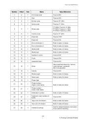
...the number of unused pins is expanded by the printer, regardless of unused pins Last byte Pins on 16 bytes (PT-H500/P700/E500) of the total number of pins (PT-H500/P700/E500: 128). As shown below, with compression, the number of pins within the print area is based on ...print head Feeding direction - 36 - 4. However, with no compression 0 pin First byte Number of offset pins Tape margin Number of print area pins Total...
...the number of unused pins is expanded by the printer, regardless of unused pins Last byte Pins on 16 bytes (PT-H500/P700/E500) of the total number of pins (PT-H500/P700/E500: 128). As shown below, with compression, the number of pins within the print area is based on ...print head Feeding direction - 36 - 4. However, with no compression 0 pin First byte Number of offset pins Tape margin Number of print area pins Total...

Master Command Reference
Page 46
..." for other pages) Status ("Printing completed") Status (Phase change "Printing" received. Status information request Status (response to receive") Sending control code/raster data Printing of tape) Computer (host) If there are cleared. Status (Phase change : "Printing") Printing 1st page Printing 2nd page Sending raster data Sending raster data Status ("Error Occurred...
..." for other pages) Status ("Printing completed") Status (Phase change "Printing" received. Status information request Status (response to receive") Sending control code/raster data Printing of tape) Computer (host) If there are cleared. Status (Phase change : "Printing") Printing 1st page Printing 2nd page Sending raster data Sending raster data Status ("Error Occurred...
Users Guide
Page 1
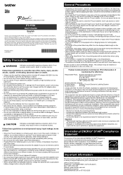
...the receiving antenna. • Increase the separation between the equipment and receiver. • Connect the equipment into the tape exit slot or AC adapter connector or battery compartment, etc. • Do not place the P-touch labeler/batteries/...International ENERGY STAR® Compliance Statement The purpose of high humidity such as bathrooms. • Do not overload the power cord. • Do not place heavy objects on, or damage the P-touch labeler, power cord or plug. has determined that the products Product Name : Brother P-touch Electronic Labeling System Model Number : PT-P700...
...the receiving antenna. • Increase the separation between the equipment and receiver. • Connect the equipment into the tape exit slot or AC adapter connector or battery compartment, etc. • Do not place the P-touch labeler/batteries/...International ENERGY STAR® Compliance Statement The purpose of high humidity such as bathrooms. • Do not overload the power cord. • Do not place heavy objects on, or damage the P-touch labeler, power cord or plug. has determined that the products Product Name : Brother P-touch Electronic Labeling System Model Number : PT-P700...
Users Guide
Page 2
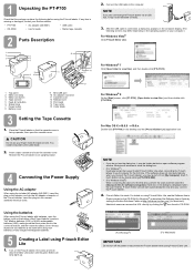
... scan and then select the [Always do not see the Software User's Guide included on your Brother reseller. • PT-P700 • AC adapter (AD-E001) • USB cable • CD-ROM • User's Guide • Starter tape cassette 2 Parts Description 1 15 2 5 3 6 7 4 9 11 8 10 14 12 13 1 Top panel 2 Editor Lite lamp 3 Editor Lite...
... scan and then select the [Always do not see the Software User's Guide included on your Brother reseller. • PT-P700 • AC adapter (AD-E001) • USB cable • CD-ROM • User's Guide • Starter tape cassette 2 Parts Description 1 15 2 5 3 6 7 4 9 11 8 10 14 12 13 1 Top panel 2 Editor Lite lamp 3 Editor Lite...


