
Service Manual
Page 3
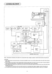
... manual describes the motor and the control box and also covers adj- TABLE OF CONTENTS DESCRIPTION OF THE MOTOR 1 SPECIFICATIONS 2 NAME OF EACH PARTS 3 PRINCIPLE OF CONTROL SYSTEM 5 CONFIGURATION 6 MD-806.816.807. 817 SPARE PARTS CODE NUMBERS OF MOTORS 7 Spare parts code for maintai- nding and adjustment. CPU&ROM LIST 11 OPERATION PANEL 12 OPERATION INSTRUCTIONS Motor control and control box use 13 ADJUSTMENT 011 DC Servomotor 14 aD Need l e pos ition detector 14 0 Motor 16 Eg Brush replacement...
... manual describes the motor and the control box and also covers adj- TABLE OF CONTENTS DESCRIPTION OF THE MOTOR 1 SPECIFICATIONS 2 NAME OF EACH PARTS 3 PRINCIPLE OF CONTROL SYSTEM 5 CONFIGURATION 6 MD-806.816.807. 817 SPARE PARTS CODE NUMBERS OF MOTORS 7 Spare parts code for maintai- nding and adjustment. CPU&ROM LIST 11 OPERATION PANEL 12 OPERATION INSTRUCTIONS Motor control and control box use 13 ADJUSTMENT 011 DC Servomotor 14 aD Need l e pos ition detector 14 0 Motor 16 Eg Brush replacement...
Service Manual
Page 5
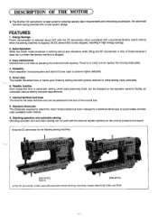
... motor fixing bracket has been changed on the control printed circuit board. * Use the DC servomotor for the lamp terminal cord can be attached to the rear of these because it does not run when the sewing machine is reduced about 50% with the DC servomotor when compared with a total system design. Standing operation and automatic sewing Standing operation and automatic sewing can be used with automatic thread trimming machines, models...
... motor fixing bracket has been changed on the control printed circuit board. * Use the DC servomotor for the lamp terminal cord can be attached to the rear of these because it does not run when the sewing machine is reduced about 50% with the DC servomotor when compared with a total system design. Standing operation and automatic sewing Standing operation and automatic sewing can be used with automatic thread trimming machines, models...
Service Manual
Page 10
Ground cables are provided for single-phase 110V types. When setting down the machine head or touching the needle, be sure to turn off the power switch, remove the front cover and confirm that the pilot lamp is applied. do not fail to turn off the power switch and confirm that the pilot lamp is not provided for both...
Ground cables are provided for single-phase 110V types. When setting down the machine head or touching the needle, be sure to turn off the power switch, remove the front cover and confirm that the pilot lamp is applied. do not fail to turn off the power switch and confirm that the pilot lamp is not provided for both...
Service Manual
Page 12
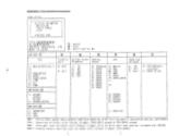
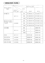
... 5: 88450 MD -8X7-ii 1 : OVERLOCK 2: ABL 3: COV 7: BAS-102 ABL: Ultra high speed twin needle overlook machine with ful l -automat ic backlatch device. (EF4-8651) COV: Covering st itcher wi th thread trimmer. (FD4-827X group & F03-825X group) NBN: Straight lock sti tcher with thread trimmer with no bird nest and shorter trimmed end. (8730) BAST: Single need le bast ing lock sti tcher with thread trimmer...
... 5: 88450 MD -8X7-ii 1 : OVERLOCK 2: ABL 3: COV 7: BAS-102 ABL: Ultra high speed twin needle overlook machine with ful l -automat ic backlatch device. (EF4-8651) COV: Covering st itcher wi th thread trimmer. (FD4-827X group & F03-825X group) NBN: Straight lock sti tcher with thread trimmer with no bird nest and shorter trimmed end. (8730) BAST: Single need le bast ing lock sti tcher with thread trimmer...
Service Manual
Page 16
C OPERATION PANEL -) Sewing machine Model B737Markll
C OPERATION PANEL -) Sewing machine Model B737Markll
Service Manual
Page 17
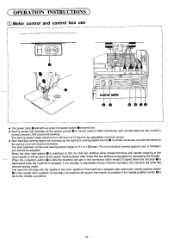
.... OPERATION INSTRUCTIONS Motor control and control box use 88 * , bCal lull ,..i. , 0 00 0 * The power lamp will light up when the power switch 0 is turned on. * Sewing speed will increase as the speed control 0 is turned toward HIGH (clockwise), and will sew in the down position if the machine is stopped after setting the needle position switch o to the needle down position. Sewing speed after thread trimming and needle stopping in the needle up position if the needle position switch...
.... OPERATION INSTRUCTIONS Motor control and control box use 88 * , bCal lull ,..i. , 0 00 0 * The power lamp will light up when the power switch 0 is turned on. * Sewing speed will increase as the speed control 0 is turned toward HIGH (clockwise), and will sew in the down position if the machine is stopped after setting the needle position switch o to the needle down position. Sewing speed after thread trimming and needle stopping in the needle up position if the needle position switch...
Service Manual
Page 18
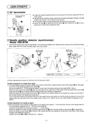
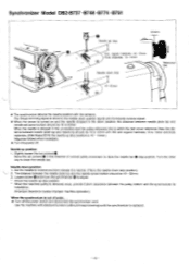
... reverse direction, the needle bar comes up stop position. And when in the reverse direction, the needle bar comes down signal and the thread trimming signal with two sensors and controls the needle down . The synchronizer detects the needle with one sensor. chine pulley. * The belt fits the machine pulley and the motor pulley as seen from the pulley side. * Adjust the belt 0 by hand. 2 Needle _position detector (synchronizer) Model...
... reverse direction, the needle bar comes up stop position. And when in the reverse direction, the needle bar comes down signal and the thread trimming signal with two sensors and controls the needle down . The synchronizer detects the needle with one sensor. chine pulley. * The belt fits the machine pulley and the motor pulley as seen from the pulley side. * Adjust the belt 0 by hand. 2 Needle _position detector (synchronizer) Model...
Service Manual
Page 19
... thread trimming) until the synchronizer is replaced. - 15 - The distance between the pulley bottom and the synchronizer for installation. (Improper clearance causes improper machine operation.) When the synchronizer is out of normal pulley movement to adjust. * Check the needle up position 1. Loosen screw and move the synchronizer 0 to raise the needle bare stop position.) 2. Use the machine with two sensors. Set the treadle to reverse...
... thread trimming) until the synchronizer is replaced. - 15 - The distance between the pulley bottom and the synchronizer for installation. (Improper clearance causes improper machine operation.) When the synchronizer is out of normal pulley movement to adjust. * Check the needle up position 1. Loosen screw and move the synchronizer 0 to raise the needle bare stop position.) 2. Use the machine with two sensors. Set the treadle to reverse...
Service Manual
Page 22
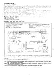
... back and the speed control unit is for setting the maximum normal sewing speed. 9. Control box Control box (Model DB2-B737) The high speed dial, backtack stitch dial, power lamp, needle position switch, one 15A fuse for the 110 - 240V single-phase type, two 5A fuses for the 200 - 240V threephase type and two 3A fuses for start backtacking speed. 7. All these parts are factory set, so that the driver does not...
... back and the speed control unit is for setting the maximum normal sewing speed. 9. Control box Control box (Model DB2-B737) The high speed dial, backtack stitch dial, power lamp, needle position switch, one 15A fuse for the 110 - 240V single-phase type, two 5A fuses for the 200 - 240V threephase type and two 3A fuses for start backtacking speed. 7. All these parts are factory set, so that the driver does not...
Service Manual
Page 25
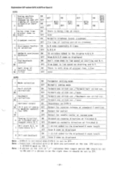
... stitch cor. /none Backward 3 correction ON Forward one stitch cor. /Backward one stitch cor. //none Optional output ON 4 y (1-2 pin of sewin- Explanation DIP switch DIPC & DIPD of Mark II DIPC 1 Sewing machine ON speci₹ication (change on and off OFF timming of reverse solenoid at finished and s- T. ON 2 tack) OFF Delay time from ON 3 presser down to the displayed B seam length...
... stitch cor. /none Backward 3 correction ON Forward one stitch cor. /Backward one stitch cor. //none Optional output ON 4 y (1-2 pin of sewin- Explanation DIP switch DIPC & DIPD of Mark II DIPC 1 Sewing machine ON speci₹ication (change on and off OFF timming of reverse solenoid at finished and s- T. ON 2 tack) OFF Delay time from ON 3 presser down to the displayed B seam length...
Service Manual
Page 31
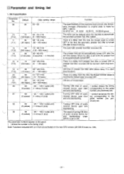
... is a delay from the time the thread wiper is turned OFF to the time the automatic presser foot lifter is turned ON after the set . 31 00 -23 - +23 (1 pulse unit) (0 pulses) (1: minus, 0: plus ) Turning ON time of quick + symbol delays the timing reverse device upon start corresponding to the pulse and end backtacking. E Parameter and timing list 1. MK II specification Parameter No. 00 Default...
... is a delay from the time the thread wiper is turned OFF to the time the automatic presser foot lifter is turned ON after the set . 31 00 -23 - +23 (1 pulse unit) (0 pulses) (1: minus, 0: plus ) Turning ON time of quick + symbol delays the timing reverse device upon start corresponding to the pulse and end backtacking. E Parameter and timing list 1. MK II specification Parameter No. 00 Default...
Service Manual
Page 34
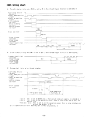
NBN timing chart A. Tread trimming timing when SW 3 is set to nine pulses can be set to ON ( when thread nipper function is set ; Inching speed area 123 , Slow speed area ( 2 stitches ) n pulse : This is deactivated ) Presser foot l itter solenoid Thread release solenoid OFF Thread nipper solenoid OFF 112 T13 : 2O0Hz T14 C. B . Sewing start timing after thread trimming Depressing treadle forward Needle down position signal Needle up posit ion signal Tension release solenoid...
NBN timing chart A. Tread trimming timing when SW 3 is set to nine pulses can be set to ON ( when thread nipper function is set ; Inching speed area 123 , Slow speed area ( 2 stitches ) n pulse : This is deactivated ) Presser foot l itter solenoid Thread release solenoid OFF Thread nipper solenoid OFF 112 T13 : 2O0Hz T14 C. B . Sewing start timing after thread trimming Depressing treadle forward Needle down position signal Needle up posit ion signal Tension release solenoid...
Service Manual
Page 37
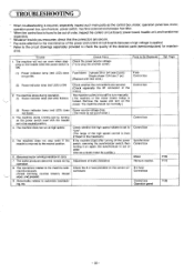
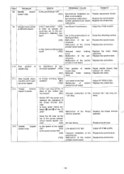
... machine stops during operation. 8. The machine starts running (variation in the neutral position. 4. The machine should run at high speed. 5. ance. noid do not work. (thread trimming, reverse rotation, thread wiper, and presser) 9. Single-phase 15A fuse (1 pc.) (Replace with the treadle set to "Low". (The range of the high speed control is from 215spm to the maximum.) If the machine stops after turning off the power switch, removing...
... machine stops during operation. 8. The machine starts running (variation in the neutral position. 4. The machine should run at high speed. 5. ance. noid do not work. (thread trimming, reverse rotation, thread wiper, and presser) 9. Single-phase 15A fuse (1 pc.) (Replace with the treadle set to "Low". (The range of the high speed control is from 215spm to the maximum.) If the machine stops after turning off the power switch, removing...
Service Manual
Page 38
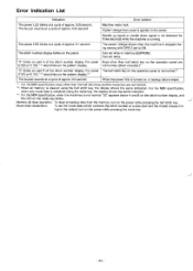
... the NBN specification, when the mode key is turned on the pattern display* 3 The buzzer sounds at a cycle of the stitch number display. When the power first is not normal, "32" appears below A and B on the stitch number display, and the LED on part A of approx. 0.5 second. Error Indication List Indication Error content The power LED blinks at a slow start and the thread release...
... the NBN specification, when the mode key is turned on the pattern display* 3 The buzzer sounds at a cycle of the stitch number display. When the power first is not normal, "32" appears below A and B on the stitch number display, and the LED on part A of approx. 0.5 second. Error Indication List Indication Error content The power LED blinks at a slow start and the thread release...
Service Manual
Page 42
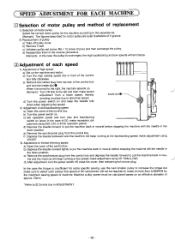
... lightly to put the machine back in neutral before stopping the machine with the needle in the down position. d) Reassemble them in front of the control box. b) Turn the high sewing speed dial in the reverse procedure. (Remark): In the case the pulley is insufficient for some specific sewing, use the next smaller pulley to increase the torque but make adjustment using VR EBT. 3) Adjustment of thread trimming speed a) Open the cover...
... lightly to put the machine back in neutral before stopping the machine with the needle in the down position. d) Reassemble them in front of the control box. b) Turn the high sewing speed dial in the reverse procedure. (Remark): In the case the pulley is insufficient for some specific sewing, use the next smaller pulley to increase the torque but make adjustment using VR EBT. 3) Adjustment of thread trimming speed a) Open the cover...
Service Manual
Page 46
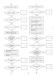
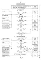
... depression steps. Yes Set the machine's thread-wiper switch to a minimum. Yes Is the thread-wiping time suitable? Yes Depress the pedal backward. Set the backtacking speed (control box) to ON. Yes Does high speed sewing begin after No completion of start and end backtack switches (operation panel) to the as desired value. Depress the treadle to neutral. Is the needle (upper) stopping position suitable? Yes...
... depression steps. Yes Set the machine's thread-wiper switch to a minimum. Yes Is the thread-wiping time suitable? Yes Depress the pedal backward. Set the backtacking speed (control box) to ON. Yes Does high speed sewing begin after No completion of start and end backtack switches (operation panel) to the as desired value. Depress the treadle to neutral. Is the needle (upper) stopping position suitable? Yes...
Service Manual
Page 50
... board. #12 Thread trimmer • Is the 1-pin plug (of the control printed-circuit board. Adjust VR TRIM (LOW). • Is the synchronizer OK? (NO) Improper installation of needle Adjust needle (lower) stop (lower) stop . printed-circuit board. - 46 - needle stop . #9 Needle (lower) stops at low speed doesn't stop . chronizer possible? (YES) Poor position of the Replace the synchronizer. noid. Replace the 8A fuse. #13 Needle (upper) • Is...
... board. #12 Thread trimmer • Is the 1-pin plug (of the control printed-circuit board. Adjust VR TRIM (LOW). • Is the synchronizer OK? (NO) Improper installation of needle Adjust needle (lower) stop (lower) stop . printed-circuit board. - 46 - needle stop . #9 Needle (lower) stops at low speed doesn't stop . chronizer possible? (YES) Poor position of the Replace the synchronizer. noid. Replace the 8A fuse. #13 Needle (upper) • Is...
Service Manual
Page 57
... hums dur- Pedal one-stitch sewing difficult. High speed OK, but no low speed. Pedal low-speed range is light. NO #103 YES Treadle lever depressed forward. Low-speed torque: OK NO YES #106 (p.66) YES Turn high-speed VR fully clockwise. .7 (P54) - 53 - Return to "START" (p.52) #104-1 (p.66) Return to "START" (p.52) #100-1 (p.64) Thread trimmer operates. #101 NO Reverse operates. #102 NO YES YES...
... hums dur- Pedal one-stitch sewing difficult. High speed OK, but no low speed. Pedal low-speed range is light. NO #103 YES Treadle lever depressed forward. Low-speed torque: OK NO YES #106 (p.66) YES Turn high-speed VR fully clockwise. .7 (P54) - 53 - Return to "START" (p.52) #104-1 (p.66) Return to "START" (p.52) #100-1 (p.64) Thread trimmer operates. #101 NO Reverse operates. #102 NO YES YES...
Service Manual
Page 79
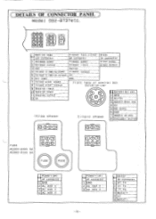
... 3 if.TH 4 Motor+ 5 Vf 6 Motor- -75- C DETAILS OF CONNECTOR PANEL Model 0B2-B737etc. 00) Machine head 12P connector Release power Release output Presser foot l ifter 6P connector Presser power Presser Input Brake 2P connector Brake Power Brake output 52 3 GND Option 4 Thread trimming power Presser output Thread trimming output OV 6 Not used GND 7 Thread wiper power 8 Thread wiper output Front face of control box synchronizer 9 Reverse input 10 Reverse power 11 Reverse output 12...
... 3 if.TH 4 Motor+ 5 Vf 6 Motor- -75- C DETAILS OF CONNECTOR PANEL Model 0B2-B737etc. 00) Machine head 12P connector Release power Release output Presser foot l ifter 6P connector Presser power Presser Input Brake 2P connector Brake Power Brake output 52 3 GND Option 4 Thread trimming power Presser output Thread trimming output OV 6 Not used GND 7 Thread wiper power 8 Thread wiper output Front face of control box synchronizer 9 Reverse input 10 Reverse power 11 Reverse output 12...
Service Manual
Page 110
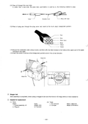
... (using a screw, and then affix two lead clamps to be sure that there is easy. Red Blue Black (two) Black Yellow Yellow (14) Secure the installation plate using a megger) to the holes at the upper part of the plate and secure the cable. (15) Insert the carbon brushes at the 6-pin plug's designated position. Crimper Molex J5800-03 Molex JHTR1031C - 106 - If, rather than a new...
... (using a screw, and then affix two lead clamps to be sure that there is easy. Red Blue Black (two) Black Yellow Yellow (14) Secure the installation plate using a megger) to the holes at the upper part of the plate and secure the cable. (15) Insert the carbon brushes at the 6-pin plug's designated position. Crimper Molex J5800-03 Molex JHTR1031C - 106 - If, rather than a new...


