
Instruction Manual
Page 4
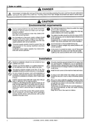
... formation may need to direct sunlight during use . Furthermore, do not get into your eyes or onto your Brother dealer or a qualified electrician for the machine. Do not connect the power cord until installation is complete, otherwise the machine may operate if the foot switch is pressed by two or more than this may cause problems with correct operation. 0 lems with correct operation. 0 The...
... formation may need to direct sunlight during use . Furthermore, do not get into your eyes or onto your Brother dealer or a qualified electrician for the machine. Do not connect the power cord until installation is complete, otherwise the machine may operate if the foot switch is pressed by two or more than this may cause problems with correct operation. 0 lems with correct operation. 0 The...
Instruction Manual
Page 5
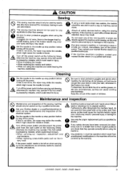
... when using the sewing machine. If this is used without these devices attached, injury may strike the needle, which might cause the needle to the needle up step position before using the machine. Cleaning Set the needle to the needle up stop position before using a work table which has casters, the casters should be secured in such a way so that if a needle breaks, parts of children. A• Turn off the power switch. LK3-B430E...
... when using the sewing machine. If this is used without these devices attached, injury may strike the needle, which might cause the needle to the needle up step position before using the machine. Cleaning Set the needle to the needle up stop position before using a work table which has casters, the casters should be secured in such a way so that if a needle breaks, parts of children. A• Turn off the power switch. LK3-B430E...

Instruction Manual
Page 6
... before Belt cover Motor cover, etc. threading, changing bobbin and needle, cleaning etc. If the ground connection is not secure, you run a high risk of operation Eye guard 0 Thread take -up solenoid cover Operate with correct operation may cause injury. serious electric shock, and problems with safety devices. Warning labels The following warning labels appear on the labels at all times when using the machine. Bide schalten...
... before Belt cover Motor cover, etc. threading, changing bobbin and needle, cleaning etc. If the ground connection is not secure, you run a high risk of operation Eye guard 0 Thread take -up solenoid cover Operate with correct operation may cause injury. serious electric shock, and problems with safety devices. Warning labels The following warning labels appear on the labels at all times when using the machine. Bide schalten...

Instruction Manual
Page 7
... 7-6. Cleaning the rotary hook 9-2. Using the bobbin thread counter 43 19 11-2. Operation panel DIP switches 44 22 12-2. Using user programs 46 23 23 13.CHANGING SPECIAL FUNCTIONS 24 USING THE MEMORY SWITCHES 48 13-1. OPERATION 5-1. Operating procedure 6. CORRECT USE 7-1. Winding the lower thread 7-5. Adjusting the needle bar height 32 7 10-2. Adjusting the shuttle race thread 11 guide 33 11 10-6. SPECIFICATIONS 2-1. Installing the machine head 3-9. Installing the head rest 3-10. Installing the foot switch 3-17. Installing the spool...
... 7-6. Cleaning the rotary hook 9-2. Using the bobbin thread counter 43 19 11-2. Operation panel DIP switches 44 22 12-2. Using user programs 46 23 23 13.CHANGING SPECIAL FUNCTIONS 24 USING THE MEMORY SWITCHES 48 13-1. OPERATION 5-1. Operating procedure 6. CORRECT USE 7-1. Winding the lower thread 7-5. Adjusting the needle bar height 32 7 10-2. Adjusting the shuttle race thread 11 guide 33 11 10-6. SPECIFICATIONS 2-1. Installing the machine head 3-9. Installing the head rest 3-10. Installing the foot switch 3-17. Installing the spool...
Instruction Manual
Page 9
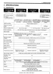
... for -2 spec.) Data storage method Number of user programs Number of cycle programs Number of stored data which can be added) Solenoid type Work clamp height Rotary hook Wiper device 17 mm max. SPECIFICATIONS 2 . set) Variable ( 21, 28, 35 stitches pre-set ) Variable ( 21, 28 35, 42, 45 stitches pre- 2 . Total number of stitches of stored data Motor Weights Power source P-ROM (Any sewing pattern can be added using BAS-PC/300...
... for -2 spec.) Data storage method Number of user programs Number of cycle programs Number of stored data which can be added) Solenoid type Work clamp height Rotary hook Wiper device 17 mm max. SPECIFICATIONS 2 . set) Variable ( 21, 28, 35 stitches pre-set ) Variable ( 21, 28 35, 42, 45 stitches pre- 2 . Total number of stitches of stored data Motor Weights Power source P-ROM (Any sewing pattern can be added using BAS-PC/300...

Instruction Manual
Page 21
... screws 0. Remove the six screws 0, and then open the cord presser plate 0 in the direction of the white arrow and pass the cords 0 through the hole 0 in the illustra- Securely connect connectors P1 to its original position. 4. board mounting plate 0) with the cord clamps le and 10. Close the cord presser plate 0 in the direction of pins Cord mark X, Y, Sewing sensor 12-pin 1 P1 (ORG2) Synchronizer 5-pin 2 P2 (SYNCHRO) Machine specification select connector 8-pin 3 P3 (SELECT) Thread...
... screws 0. Remove the six screws 0, and then open the cord presser plate 0 in the direction of the white arrow and pass the cords 0 through the hole 0 in the illustra- Securely connect connectors P1 to its original position. 4. board mounting plate 0) with the cord clamps le and 10. Close the cord presser plate 0 in the direction of pins Cord mark X, Y, Sewing sensor 12-pin 1 P1 (ORG2) Synchronizer 5-pin 2 P2 (SYNCHRO) Machine specification select connector 8-pin 3 P3 (SELECT) Thread...

Instruction Manual
Page 23
... the direction of bed cover LO. 2. 3-15 . Mark II 16 LK3-6430E-, B431E-, B432E-, B433E- Installing the belt cover 3. spring washer and NOTE: If using the optional two-pedal foot switch, change the setting of the control box 0. 2. If the foot switch is just hooked loosely onto the work table leg, move the foot switch at least 10 mm away from the leg. Loosen the two screws 0 of the upper cover...
... the direction of bed cover LO. 2. 3-15 . Mark II 16 LK3-6430E-, B431E-, B432E-, B433E- Installing the belt cover 3. spring washer and NOTE: If using the optional two-pedal foot switch, change the setting of the control box 0. 2. If the foot switch is just hooked loosely onto the work table leg, move the foot switch at least 10 mm away from the leg. Loosen the two screws 0 of the upper cover...

Instruction Manual
Page 26
... . Mark II OPERATION 5-1 . O RESET switch . Use this switch when you want to operate only the feed mechanism in the display O. O TEST switch Use this switch to check a pattern. Each time the switch is pressed, one of each time the switch is pressed to wind the lower thread. Press this switch to shown the program number setting. 19 LK3-B430E-, B431E-, 0432E-, B433E- WIND switch Press this...
... . Mark II OPERATION 5-1 . O RESET switch . Use this switch when you want to operate only the feed mechanism in the display O. O TEST switch Use this switch to check a pattern. Each time the switch is pressed, one of each time the switch is pressed to wind the lower thread. Press this switch to shown the program number setting. 19 LK3-B430E-, B431E-, 0432E-, B433E- WIND switch Press this...

Instruction Manual
Page 27
... show the bobbin thread or production counter setting. Illuminates when the SELECT switch 0 is pressed to shown the Y-scale setting. LK3-8430E-, B431E-, 8432E-, 8433E- OPERATION brother B430E Markll Series O PROGRAM NO. POWER x 0 O X-SCALE RESET jv 0 Y-SCALE a) O SPEED 0 OEM COUNTER P1 P2 P3) P4 /3 0 14 B0BBIN.WIND SELECT A • X-SCALE indicator • Y-SCALE indicator e SPEED indicator e COUNTER indicator ® DISPLAY SET switches e User program...
... show the bobbin thread or production counter setting. Illuminates when the SELECT switch 0 is pressed to shown the Y-scale setting. LK3-8430E-, B431E-, 8432E-, 8433E- OPERATION brother B430E Markll Series O PROGRAM NO. POWER x 0 O X-SCALE RESET jv 0 Y-SCALE a) O SPEED 0 OEM COUNTER P1 P2 P3) P4 /3 0 14 B0BBIN.WIND SELECT A • X-SCALE indicator • Y-SCALE indicator e SPEED indicator e COUNTER indicator ® DISPLAY SET switches e User program...

Instruction Manual
Page 31
... winder thread tension stud 0 clokwise; press the foot switch 0 to adjust. * If the thread winds on . • 6. pressing the foot switch 0 until the lower thread stops being wound onto the bobbin. c=r 0 • 0 8. Check that the needle is completed, depress it winds on the operation panel will automatically return to its original position after the machine starts B0BBIN.WIND 0 operating. WIND switch 0. • 5. Winding the lower thread A CAUTION 7. Release the foot switch 0. 7. 7-4 . Turn on the power switch...
... winder thread tension stud 0 clokwise; press the foot switch 0 to adjust. * If the thread winds on . • 6. pressing the foot switch 0 until the lower thread stops being wound onto the bobbin. c=r 0 • 0 8. Check that the needle is completed, depress it winds on the operation panel will automatically return to its original position after the machine starts B0BBIN.WIND 0 operating. WIND switch 0. • 5. Winding the lower thread A CAUTION 7. Release the foot switch 0. 7. 7-4 . Turn on the power switch...

Instruction Manual
Page 32
... power switch before removing and replacing the bobbin case, otherwise the machine may need to open it out proximately 30 mm of the arrow when the thread is depressed by mistake and serious injury could result. from the thread hole 0. 7. Check that the bobbin turns in the above table may operate if the foot switch is pulled at this time. 7-6 . Sewing conditions and thread tension Ordinary materials Denim Use Standard hook...
... power switch before removing and replacing the bobbin case, otherwise the machine may need to open it out proximately 30 mm of the arrow when the thread is depressed by mistake and serious injury could result. from the thread hole 0. 7. Check that the bobbin turns in the above table may operate if the foot switch is pulled at this time. 7-6 . Sewing conditions and thread tension Ordinary materials Denim Use Standard hook...

Instruction Manual
Page 35
... the machine while sewing, as this may come into contact with the needle and break the tip of the material, release the foot switch. SEWING A CAUTION Turn off the power switch at its highest position. Place the material to the 1st step, the work clamp 0 will start operating. 3. Before starting 2nd Step position and the work clamp 0 will rise. 0 * Note that the needle bar is completed and the thread has...
... the machine while sewing, as this may come into contact with the needle and break the tip of the material, release the foot switch. SEWING A CAUTION Turn off the power switch at its highest position. Place the material to the 1st step, the work clamp 0 will start operating. 3. Before starting 2nd Step position and the work clamp 0 will rise. 0 * Note that the needle bar is completed and the thread has...
Instruction Manual
Page 39
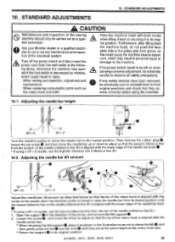
... machine head with the lower edge of the needle (reference line (b) ). 1. Adjusting the needle bar height 0 ( 1 a (DP x 5) DP x 17 Turn the machine pulley to move the needle bar to its original position. Then remove the rubber plug 0, loosen the set screw 0 and then move the driver to adjust so that the tip of the rotary hook is aligned with the needle center line. * When returning the felt support...
... machine head with the lower edge of the needle (reference line (b) ). 1. Adjusting the needle bar height 0 ( 1 a (DP x 5) DP x 17 Turn the machine pulley to move the needle bar to its original position. Then remove the rubber plug 0, loosen the set screw 0 and then move the driver to adjust so that the tip of the rotary hook is aligned with the needle center line. * When returning the felt support...

Instruction Manual
Page 42
... screws 0, and then remove the needle plate 0. 3. Place the thread trimming connecting rod Oonto the connecting rod lever pin 0, and then install to the outside of 0.5 mm from the connecting rod lever pin 0. 0- 0.5mm e 4. Mark II Install the fixed knife at a distance of the collar at this time, check that the movable knife 0 and the fixed knife cut the thread cleanly. At this time. Open the large shuttle hook cover, remove the screws...
... screws 0, and then remove the needle plate 0. 3. Place the thread trimming connecting rod Oonto the connecting rod lever pin 0, and then install to the outside of 0.5 mm from the connecting rod lever pin 0. 0- 0.5mm e 4. Mark II Install the fixed knife at a distance of the collar at this time, check that the movable knife 0 and the fixed knife cut the thread cleanly. At this time. Open the large shuttle hook cover, remove the screws...

Instruction Manual
Page 48
... memory settings If the sewing machine stops operating normally, the cause may be shown in the table above. 5. Press the TEST switch 0 again to return the display to ON. 41 LK3-B430E-, B431E-, B432E-, B433E- In such cases, carry out the following procedure to clear the memory, and also check the DIP switch settings. [ Method ] While pressing the RESET...
... memory settings If the sewing machine stops operating normally, the cause may be shown in the table above. 5. Press the TEST switch 0 again to return the display to ON. 41 LK3-B430E-, B431E-, B432E-, B433E- In such cases, carry out the following procedure to clear the memory, and also check the DIP switch settings. [ Method ] While pressing the RESET...

Instruction Manual
Page 55
CHANGING SPECIAL FUNCTIONS USING THE MEMORY SWITCHES The functions of shipment the power off and then back on again. 1. While pressing the TEST switch 0, press the BOBBIN. IIIIMemory switches 00 - Test feeding is carried out stitch by stitch when the foot switch is lower. Work clamp closes when it moves to the starting point after sewing starts.) memo-03 When sewing using the optional spring for extra-heavy...
CHANGING SPECIAL FUNCTIONS USING THE MEMORY SWITCHES The functions of shipment the power off and then back on again. 1. While pressing the TEST switch 0, press the BOBBIN. IIIIMemory switches 00 - Test feeding is carried out stitch by stitch when the foot switch is lower. Work clamp closes when it moves to the starting point after sewing starts.) memo-03 When sewing using the optional spring for extra-heavy...

Instruction Manual
Page 59
... the connection of and an error the problem. Press the RESET switch and specify a correct number. Turn off . code will sound display window. Stitch pattern data overlaps the sewing area when area limiting is not correctly inserted. TABLE OF ERROR CODES 14. E-80 E-81 E-82 Motor PROM is active. Presser cannot be lowered. Adjusting the needle up stop position. (Refer to "16. E-90 Abnormal drop in severe injury. Check...
... the connection of and an error the problem. Press the RESET switch and specify a correct number. Turn off . code will sound display window. Stitch pattern data overlaps the sewing area when area limiting is not correctly inserted. TABLE OF ERROR CODES 14. E-80 E-81 E-82 Motor PROM is active. Presser cannot be lowered. Adjusting the needle up stop position. (Refer to "16. E-90 Abnormal drop in severe injury. Check...

Instruction Manual
Page 69
... position is incorrect. Bobbin winder thread tension stud height is incorrect. Thread take-up lever stroke Adjust the thread take-up lever stroke. 34 *1 Not applicable for the B432E Mark II. *2 B432E Mark II only. 1K3-B430E-, B431E-, B432E-, 8433E- Adjust the position of the work clamp and top of needle plate Presser plate and presser arm lever support lubrication __- Thread wiper does not operate correctly. Thread winding amount Adjust the position of the work clamp lubrication Distance between presser arm lever - Upper thread length Adjust...
... position is incorrect. Bobbin winder thread tension stud height is incorrect. Thread take-up lever stroke Adjust the thread take-up lever stroke. 34 *1 Not applicable for the B432E Mark II. *2 B432E Mark II only. 1K3-B430E-, B431E-, B432E-, 8433E- Adjust the position of the work clamp and top of needle plate Presser plate and presser arm lever support lubrication __- Thread wiper does not operate correctly. Thread winding amount Adjust the position of the work clamp lubrication Distance between presser arm lever - Upper thread length Adjust...

Instruction Manual
Page 70
... Problem Cause Check Remedy Page Upper thread breaks. Upper thread tension Adjust the upper -'thread tension. 26 Needle is 23 facin• forward. thick for the material. .7z LK3-8430E-, 8431E-, 8432E-, 8433E- spring tension and height are damaged. File smooth or replace the afffected part. Skipped stitches occur. Clearance between driver and needle Bent needle Needle direction Adjust the needle clearance. 33 Adjust the needle bar lift amount. 32 Adjust the driver needle guard. 33 Replace the needle. Incorrect needle and rotary hook timing. Lower...
... Problem Cause Check Remedy Page Upper thread breaks. Upper thread tension Adjust the upper -'thread tension. 26 Needle is 23 facin• forward. thick for the material. .7z LK3-8430E-, 8431E-, 8432E-, 8433E- spring tension and height are damaged. File smooth or replace the afffected part. Skipped stitches occur. Clearance between driver and needle Bent needle Needle direction Adjust the needle clearance. 33 Adjust the needle bar lift amount. 32 Adjust the driver needle guard. 33 Replace the needle. Incorrect needle and rotary hook timing. Lower...

Instruction Manual
Page 71
... thread tension Lower thread tension Thread take-up spring tension and hei•ht Adjust the upper thread tension. 26 Adjust the lower thread tension. 26 Adjust the tension and height of material. Problem Cause Check 16. Thread jamming. Skipped stitches at the sewing end. Shuttle race thread guide is incorrect. Thread take -up spring tension and hei•ht are incorrect. Incorrect needle and rotary hook timing. Thread take-up lever stroke Adjust the thread take -up lever stroke. 34 Incorrect thread tightness. Shuttle race thread guide position Needle bar...
... thread tension Lower thread tension Thread take-up spring tension and hei•ht Adjust the upper thread tension. 26 Adjust the lower thread tension. 26 Adjust the tension and height of material. Problem Cause Check 16. Thread jamming. Skipped stitches at the sewing end. Shuttle race thread guide is incorrect. Thread take -up spring tension and hei•ht are incorrect. Incorrect needle and rotary hook timing. Thread take-up lever stroke Adjust the thread take -up lever stroke. 34 Incorrect thread tightness. Shuttle race thread guide position Needle bar...


