
Parts List
Page 6
... & PANEL-MAIN HARNESSES 2 HARNESS SUPPORT SPONGE 2 TAPTITE, CUP B M4X12 2 TOP COVER STOPPER 12 2 TAPTITE, CUP B M4X12 2 TAPTITE, CUP S M3X6 4 TAPTITE, BIND B M4X12 1 SHIELD FILM 1 DOCUMENT GUIDE BASE, WHITE(1138) 1 LASER CAUTION LABEL 1 TONER CAUTION LABEL NOT USED 1 HEARTER HARNESS (BROWN AND BLUE WIRES) 1 CONTROL PANEL ASSY, WHITE(1138) 1 CONTROL PANEL, WHITE(1138) 1 CONTROL PANEL PCB ASSY 1 LCD 1 FPC KEY 1 PANEL REAR COVER 1 DOCUMENT PRESSURE BAR 1 DOCUMENT PRESSURE BAR SPRING 1 SEPARATION RUBBER 1 ADF SPRING...
... & PANEL-MAIN HARNESSES 2 HARNESS SUPPORT SPONGE 2 TAPTITE, CUP B M4X12 2 TOP COVER STOPPER 12 2 TAPTITE, CUP B M4X12 2 TAPTITE, CUP S M3X6 4 TAPTITE, BIND B M4X12 1 SHIELD FILM 1 DOCUMENT GUIDE BASE, WHITE(1138) 1 LASER CAUTION LABEL 1 TONER CAUTION LABEL NOT USED 1 HEARTER HARNESS (BROWN AND BLUE WIRES) 1 CONTROL PANEL ASSY, WHITE(1138) 1 CONTROL PANEL, WHITE(1138) 1 CONTROL PANEL PCB ASSY 1 LCD 1 FPC KEY 1 PANEL REAR COVER 1 DOCUMENT PRESSURE BAR 1 DOCUMENT PRESSURE BAR SPRING 1 SEPARATION RUBBER 1 ADF SPRING...
Service Manual
Page 8
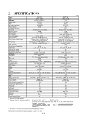
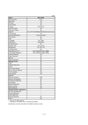
... Board Optional Mac Board Interface/Interface Cable SCANNER Color/Mono dpi Gray Scale Twain Formats (Import) Formats (Export) ADF (pages) OCR COPY dpi Collating Reduction/Enlargement Sorting FAX Modem/Speed (bps) CCITT Group Coding Method Error Correction Mode (ECM) Transmission Speed (sec) Gray Scale Super Fine Smoothing Multi-Resolution TX Input/Output Width LCD Size Handset Duplex Speaker Phone FAX3750 White (1397) Available with option *1 [YL (VA)] [6 ppm] [600 x 600] [200] - [Windows...
... Board Optional Mac Board Interface/Interface Cable SCANNER Color/Mono dpi Gray Scale Twain Formats (Import) Formats (Export) ADF (pages) OCR COPY dpi Collating Reduction/Enlargement Sorting FAX Modem/Speed (bps) CCITT Group Coding Method Error Correction Mode (ECM) Transmission Speed (sec) Gray Scale Super Fine Smoothing Multi-Resolution TX Input/Output Width LCD Size Handset Duplex Speaker Phone FAX3750 White (1397) Available with option *1 [YL (VA)] [6 ppm] [600 x 600] [200] - [Windows...
Service Manual
Page 9
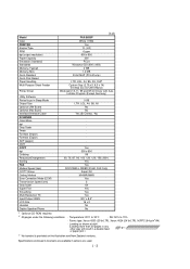
... way will result in Sleep Mode Output Size Optional LAN Board Optional Mac Board Interface/Interface Cable SCANNER Color/Mono dpi Gray Scale Twain Formats (Import) Formats (Export) ADF (pages) OCR COPY dpi Collating Reduction/Enlargement Sorting FAX Modem/Speed (bps) CCITT Group Coding Method Error Correction Mode (ECM) Transmission Speed (sec) Gray Scale Super Fine Smoothing Multi-Resolution TX Input/Output Width LCD Size Handset Duplex Speaker Phone (1/2) FAX-8650P White (1138) Yes YL (VA...
... way will result in Sleep Mode Output Size Optional LAN Board Optional Mac Board Interface/Interface Cable SCANNER Color/Mono dpi Gray Scale Twain Formats (Import) Formats (Export) ADF (pages) OCR COPY dpi Collating Reduction/Enlargement Sorting FAX Modem/Speed (bps) CCITT Group Coding Method Error Correction Mode (ECM) Transmission Speed (sec) Gray Scale Super Fine Smoothing Multi-Resolution TX Input/Output Width LCD Size Handset Duplex Speaker Phone (1/2) FAX-8650P White (1138) Yes YL (VA...
Service Manual
Page 10
...-Transmission No Message Center No OGM No ICM Recording Time No Paging Yes Toll Saver No Fax & Voice Mail Box No Fax- & Voice-on-Demand No FAX Forwarding Yes FAX Retrieval Yes General Energy Star Compliance Yes Memory (Standard) 4 MB Memory (Opt Upgrade) Simultaneous Operation No Available with option *1 [ (PRINTER/FAX, PRINTER/SCAN, PRINTER/COPY) ] Data Modem Bundled Software Applications No Available with option *1 PC-FAX (Send/Receive) [SMSI] Scanner Application [Brother] Viewer Application [Visioneer] Network Application No...
...-Transmission No Message Center No OGM No ICM Recording Time No Paging Yes Toll Saver No Fax & Voice Mail Box No Fax- & Voice-on-Demand No FAX Forwarding Yes FAX Retrieval Yes General Energy Star Compliance Yes Memory (Standard) 4 MB Memory (Opt Upgrade) Simultaneous Operation No Available with option *1 [ (PRINTER/FAX, PRINTER/SCAN, PRINTER/COPY) ] Data Modem Bundled Software Applications No Available with option *1 PC-FAX (Send/Receive) [SMSI] Scanner Application [Brother] Viewer Application [Visioneer] Network Application No...
Service Manual
Page 11
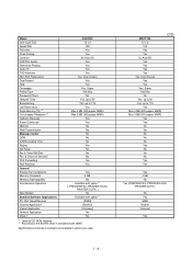
... No Message Center No OGM No ICM Recording Time No Paging No Fax & Voice Mail Box No Fax- & Voice-on-Demand No FAX Forwarding Yes FAX Retrieval Yes General Memory (Standard) 4 MB Memory (Opt Upgrade) No Simultaneous Operation No Data Modem No Remote Diagnostics Yes Memory Security Yes Memory Backup Yes Bundled Software Applications PC-FAX (Send/Receive) Scanner Application Viewer Application Network Application No Class 1 Yes *1 Optional...
... No Message Center No OGM No ICM Recording Time No Paging No Fax & Voice Mail Box No Fax- & Voice-on-Demand No FAX Forwarding Yes FAX Retrieval Yes General Memory (Standard) 4 MB Memory (Opt Upgrade) No Simultaneous Operation No Data Modem No Remote Diagnostics Yes Memory Security Yes Memory Backup Yes Bundled Software Applications PC-FAX (Send/Receive) Scanner Application Viewer Application Network Application No Class 1 Yes *1 Optional...

Service Manual
Page 15
... of the facsimile equipment, type the following: A:\ICEN filename /b Then press the ENTER key. II - 2 The equipment beeps and shows the "CONNECTING" on the LCD and starts receiving data downloaded from the command line and press the ENTER key. (4) Check that your computer. (Or, copy the update data and transfer utility onto the same directory of the hard disk.) (2) Click the Start button, point to Programs, and then click...
... of the facsimile equipment, type the following: A:\ICEN filename /b Then press the ENTER key. II - 2 The equipment beeps and shows the "CONNECTING" on the LCD and starts receiving data downloaded from the command line and press the ENTER key. (4) Check that your computer. (Or, copy the update data and transfer utility onto the same directory of the hard disk.) (2) Click the Start button, point to Programs, and then click...

Service Manual
Page 27
... Sheet feeder cover sensor Registration sensor Paper ejection sensor Toner sensor Toner thermister Heater thermister Hook switch* Type Photosensor Photosensor Photosensor Photosensor Photosensor Photosensor Photosensor Thermister Thermister Mechanical switch Located on Control panel PCB ASSY (Document sensor PCB) Control panel PCB ASSY (Document sensor PCB) Main PCB Main PCB Main PCB High-voltage power supply PCB Toner sensor PCB Toner sensor PCB Heat-fixing unit Hook switch PCB* *Not provided on the FAX-8650P...
... Sheet feeder cover sensor Registration sensor Paper ejection sensor Toner sensor Toner thermister Heater thermister Hook switch* Type Photosensor Photosensor Photosensor Photosensor Photosensor Photosensor Photosensor Thermister Thermister Mechanical switch Located on Control panel PCB ASSY (Document sensor PCB) Control panel PCB ASSY (Document sensor PCB) Main PCB Main PCB Main PCB High-voltage power supply PCB Toner sensor PCB Toner sensor PCB Heat-fixing unit Hook switch PCB* *Not provided on the FAX-8650P...
Service Manual
Page 39
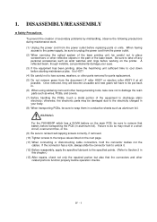
... and new gears will have to be sure to damage the resin parts such as aluminum foil. When having access to the power supply, be sure to discharge static electricity; 1. otherwise, the electronic parts may result in . (6) When using soldering irons and other parts removed for parts replacement. (5) Do not remove gears from the power outlet. (2) When servicing the optical system of the laser printing unit...
... and new gears will have to be sure to damage the resin parts such as aluminum foil. When having access to the power supply, be sure to discharge static electricity; 1. otherwise, the electronic parts may result in . (6) When using soldering irons and other parts removed for parts replacement. (5) Do not remove gears from the power outlet. (2) When servicing the optical system of the laser printing unit...

Service Manual
Page 62
1.9 Handset Mount and Hook Switch PCB (for the FAX3750/MFC7750) Side Cover (for the FAX-8650P) (1) Open the top cover. (2) Remove one of two screws from each of the bosses provided on the main cover. The hook switch harness* is connected to the left and its upper end works out of right and left top cover stoppers, then fully open the top cover. (3) Remove the two screws...
1.9 Handset Mount and Hook Switch PCB (for the FAX3750/MFC7750) Side Cover (for the FAX-8650P) (1) Open the top cover. (2) Remove one of two screws from each of the bosses provided on the main cover. The hook switch harness* is connected to the left and its upper end works out of right and left top cover stoppers, then fully open the top cover. (3) Remove the two screws...

Service Manual
Page 88
... ready to the initial stage of the maintenance mode. • If an invalid function code is entered, the equipment resumes the initial stage of the maintenance mode. To select one second and displays " " on the control panel. (The details of the maintenance mode, a mode in this order. V - 1 1. Within 2 seconds FAX-8650P: To make the equipment enter the maintenance mode, press the Function, *, 2, 8, 6, and 4 keys in which the equipment is placed in...
... ready to the initial stage of the maintenance mode. • If an invalid function code is entered, the equipment resumes the initial stage of the maintenance mode. To select one second and displays " " on the control panel. (The details of the maintenance mode, a mode in this order. V - 1 1. Within 2 seconds FAX-8650P: To make the equipment enter the maintenance mode, press the Function, *, 2, 8, 6, and 4 keys in which the equipment is placed in...

Service Manual
Page 89
2. LIST OF MAINTENANCE-MODE FUNCTIONS Function Code 01 02 03 04 05 06 07 08 09 10 11 12 13 14 15 32 55 74 82 87 91 99 Maintenance-mode Functions Function EEPROM Parameter Initialization Reference Subsection (Page) 3.1 (V-4) Printout of Scanning Compensation Data 3.2 (V-5) ADF* Performance Test Test Pattern 1 Firmware Switch Setting Printout of Firmware Switch Data Operational Check of LCD Operational Check of Control Panel PCB (Check of Keys and Buttons) 3.3 (V-7) 3.4 (V-8) 3.5 (V-9) 3.5 (V-50) 3.6 (V-53) 3.7 (V-53) Sensor Operational Check CIS Scanner Area Setting EEPROM Customizing ...
2. LIST OF MAINTENANCE-MODE FUNCTIONS Function Code 01 02 03 04 05 06 07 08 09 10 11 12 13 14 15 32 55 74 82 87 91 99 Maintenance-mode Functions Function EEPROM Parameter Initialization Reference Subsection (Page) 3.1 (V-4) Printout of Scanning Compensation Data 3.2 (V-5) ADF* Performance Test Test Pattern 1 Firmware Switch Setting Printout of Firmware Switch Data Operational Check of LCD Operational Check of Control Panel PCB (Check of Keys and Buttons) 3.3 (V-7) 3.4 (V-8) 3.5 (V-9) 3.5 (V-50) 3.6 (V-53) 3.7 (V-53) Sensor Operational Check CIS Scanner Area Setting EEPROM Customizing ...
Service Manual
Page 121
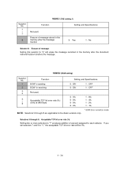
... setting) Selector No. 1 2 3 4 Function ECM* in sending ECM* in the memory after the document retrieval feature transfers the message. l Selectors 5 through 8 are applicable to the Asian versions only. Selector No. 1 | 7 8 WSW21 (TAD setting 1) Function Setting and Specifications Not used . 5 | 8 Acceptable TCF bit error rate (%) (Only at 4800 bps) Setting and Specifications 0: ON 0: ON 1: OFF 1: OFF 0: 0% 0: 0% 0: 0% 0: 0% 1: 8% 1: 4% 1: 2% 1: 1% * ECM: Error correction mode NOTE: Selectors 5 through 8: Acceptable TCF bit error rate (%) Setting...
... setting) Selector No. 1 2 3 4 Function ECM* in sending ECM* in the memory after the document retrieval feature transfers the message. l Selectors 5 through 8 are applicable to the Asian versions only. Selector No. 1 | 7 8 WSW21 (TAD setting 1) Function Setting and Specifications Not used . 5 | 8 Acceptable TCF bit error rate (%) (Only at 4800 bps) Setting and Specifications 0: ON 0: ON 1: OFF 1: OFF 0: 0% 0: 0% 0: 0% 0: 0% 1: 8% 1: 4% 1: 2% 1: 1% * ECM: Error correction mode NOTE: Selectors 5 through 8: Acceptable TCF bit error rate (%) Setting...
Service Manual
Page 142
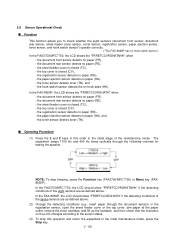
... top cover, jam paper at the paper outlet, remove the toner cartridge, and lift up the handset), and then check that the indication on -hook state (HK). NOTE: To stop this order in this operation and return the equipment to check whether the eight sensors (document front sensor, document rear sensor, sheet feeder cover sensor, cover sensor, registration sensor, paper ejection sensor, toner sensor, and hook switch sensor*) operate correctly. (*The FAX-8650P...
... top cover, jam paper at the paper outlet, remove the toner cartridge, and lift up the handset), and then check that the indication on -hook state (HK). NOTE: To stop this order in this operation and return the equipment to check whether the eight sensors (document front sensor, document rear sensor, sheet feeder cover sensor, cover sensor, registration sensor, paper ejection sensor, toner sensor, and hook switch sensor*) operate correctly. (*The FAX-8650P...

Service Manual
Page 144
... the 8 and 7 keys. V - 57 The above operation makes the user's equipment send CNG to receive the transmission log from the user's equipment. Your equipment will start to your equipment for analyzing problems arising in the user's equipment. 3.11 Equipment Error Code Indication n Function This function displays an error code of the user's equipment at a remote location from the user's equipment, press the Start key of the maintenance mode. FAX-8650P: Press the Menu, Mode, and 0 keys in this order.
... the 8 and 7 keys. V - 57 The above operation makes the user's equipment send CNG to receive the transmission log from the user's equipment. Your equipment will start to your equipment for analyzing problems arising in the user's equipment. 3.11 Equipment Error Code Indication n Function This function displays an error code of the user's equipment at a remote location from the user's equipment, press the Start key of the maintenance mode. FAX-8650P: Press the Menu, Mode, and 0 keys in this order.

Service Manual
Page 148
... help the user or the service personnel promptly locate the cause of a problem (if any), the facsimile equipment incorporates the self-diagnostic functions which display error messages for approximately 4 seconds and shows the error message on the LCD CHECK PAPER COVER OPEN PRINTER JAM DOCUMENT JAM Probable Cause Even after the document has been fed by the specified amount. The cover sensor detects that the top cover is not closed or the sheet feeder cover...
... help the user or the service personnel promptly locate the cause of a problem (if any), the facsimile equipment incorporates the self-diagnostic functions which display error messages for approximately 4 seconds and shows the error message on the LCD CHECK PAPER COVER OPEN PRINTER JAM DOCUMENT JAM Probable Cause Even after the document has been fed by the specified amount. The cover sensor detects that the top cover is not closed or the sheet feeder cover...

Service Manual
Page 149
... DOCUMENT JAM Probable Cause n Document loading error (1) The document rear sensor detects no toner. "XX" indicates an error code. This message appears for one minute. (You can turn this message appears, recording is not enough toner. Refer to [ 2 ] on pages VI-4 and VI-5. SET CARTRIDGE The toner sensor has detected that there is loaded. COOLING DOWN PLEASE WAIT (Appear alternately.) MACHINE ERROR XX PRESS STOP KEY (Appear alternately.) CHANGE DRUM SOON PC BUSY OR FAIL...
... DOCUMENT JAM Probable Cause n Document loading error (1) The document rear sensor detects no toner. "XX" indicates an error code. This message appears for one minute. (You can turn this message appears, recording is not enough toner. Refer to [ 2 ] on pages VI-4 and VI-5. SET CARTRIDGE The toner sensor has detected that there is loaded. COOLING DOWN PLEASE WAIT (Appear alternately.) MACHINE ERROR XX PRESS STOP KEY (Appear alternately.) CHANGE DRUM SOON PC BUSY OR FAIL...

Service Manual
Page 151
... cover opened. ) Document too long to Section 1.2, (13). Refer to scan. ) Document not detected by the document rear sensor. ) 50% or more faulty of white level data. ) One-line feeding time-out error. ) One-line scanning time-out error. ) Abnormal scanning reference voltage. ) Less than 50% faulty of white level data. ) Error codes in parentheses do not appear in the "MACHINE ERROR X X", since those errors are displayed as messages described in "[ 1 ] Error messages on the LCD." The paper ejection...
... cover opened. ) Document too long to Section 1.2, (13). Refer to scan. ) Document not detected by the document rear sensor. ) 50% or more faulty of white level data. ) One-line feeding time-out error. ) One-line scanning time-out error. ) Abnormal scanning reference voltage. ) Less than 50% faulty of white level data. ) Error codes in parentheses do not appear in the "MACHINE ERROR X X", since those errors are displayed as messages described in "[ 1 ] Error messages on the LCD." The paper ejection...
Service Manual
Page 162
... a metal portion of the machine to check again if the repaired section works correctly. VI - 15 After repairing the defective section, be of use for future trouble occurrence. 2.3 Checking prior to Troubleshooting Prior to proceeding to the troubleshooting procedures, check that: (1) Each voltage level on AC input lines and DC lines is impossible to anticipate all of the possible problems which may occur in...
... a metal portion of the machine to check again if the repaired section works correctly. VI - 15 After repairing the defective section, be of use for future trouble occurrence. 2.3 Checking prior to Troubleshooting Prior to proceeding to the troubleshooting procedures, check that: (1) Each voltage level on AC input lines and DC lines is impossible to anticipate all of the possible problems which may occur in...

Service Manual
Page 167
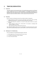
At the printer side l Check the connection of the main-high-voltage flat cable. CIS unit At the printer side l Clean the paper path which may be taken At the scanner Check the following components: - l Replace the drum unit. CIS unit At the printer side l Replace the drum unit. l Replace the heat-fixing unit. VI - 20 Trouble (5) Black and blurred vertical stripes (6) Black and blurred horizontal stripes Action to its home position. l If they appear at 94-mm...
At the printer side l Check the connection of the main-high-voltage flat cable. CIS unit At the printer side l Clean the paper path which may be taken At the scanner Check the following components: - l Replace the drum unit. CIS unit At the printer side l Replace the drum unit. l Replace the heat-fixing unit. VI - 20 Trouble (5) Black and blurred vertical stripes (6) Black and blurred horizontal stripes Action to its home position. l If they appear at 94-mm...
Service Manual
Page 168
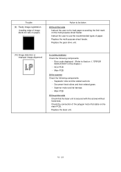
... PCB - Document feed rollers and their related gears - l Instruct the user to use the recommended types of the polygon motor flat cable on the multi-purpose sheet feeder. l Replace the multi-purpose sheet feeder. Main PCB At the scanner Check the following components: - Main PCB At the printer side l Check that the laser unit is secured with the screws without looseness. l Check the connection of paper. VI - 21 l Replace the gear drive unit. (10) Image distortion...
... PCB - Document feed rollers and their related gears - l Instruct the user to use the recommended types of the polygon motor flat cable on the multi-purpose sheet feeder. l Replace the multi-purpose sheet feeder. Main PCB At the scanner Check the following components: - Main PCB At the printer side l Check that the laser unit is secured with the screws without looseness. l Check the connection of paper. VI - 21 l Replace the gear drive unit. (10) Image distortion...


