
Instruction Manual - English
Page 3
... may cause problems with correct operation. Temperatures which are lower or higher than this may cause problems with correct operation. Lightning may cause problems with correct operation. The sewing machine weighs more people. CAUTION Environmental requirements Use the sewing machine in an area which could result in the belt, and serious injury could occur. Install the pulley covers (sold separately) to direct sunlight during use . Installation Machine installation should...
... may cause problems with correct operation. Temperatures which are lower or higher than this may cause problems with correct operation. Lightning may cause problems with correct operation. The sewing machine weighs more people. CAUTION Environmental requirements Use the sewing machine in an area which could result in the belt, and serious injury could occur. Install the pulley covers (sold separately) to direct sunlight during use . Installation Machine installation should...
Instruction Manual - English
Page 4
... starting work . BM-917B, 917C iii When threading the needle ! Turn off as the loopers and knife * The motor will not be covered by operators who have been removed, be absolutely sure to re-install them to the machine will keep turning even after one cycle. Wait until the motor stops fully before starting work Be sure to wear protective goggles when using the machine. When replacing consumable parts...
... starting work . BM-917B, 917C iii When threading the needle ! Turn off as the loopers and knife * The motor will not be covered by operators who have been removed, be absolutely sure to re-install them to the machine will keep turning even after one cycle. Wait until the motor stops fully before starting work Be sure to wear protective goggles when using the machine. When replacing consumable parts...
Instruction Manual - English
Page 6
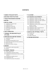
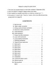
... Adjusting the presser arm pressure 16 11.CLEANING 17 12.STANDARD ADJUSTMENTS 18 12-1. Sewing 14 10.THREAD TENSION 15 10-1. Adjusting the needle and looper timing.........18 12-3. Button clamp set 24 14.TROUBLESHOOTING 25 BM-917B, 917C CONTENTS 1.NAMES OF MAJOR PARTS 1 2.MACHINE SPECIFICATIONS 1 3.TABLE PROCESSING DIAGRAM ......... 2 4.MOTOR 3 5.INSTALLATION 4 5-1. Setting the number of thrust 20 12-7. Adjusting the thread presser tension opening amount 15 10-4. Adjusting the needle guide 19 12-5. Adjusting the button opener 21 12-10. Feed plate...
... Adjusting the presser arm pressure 16 11.CLEANING 17 12.STANDARD ADJUSTMENTS 18 12-1. Sewing 14 10.THREAD TENSION 15 10-1. Adjusting the needle and looper timing.........18 12-3. Button clamp set 24 14.TROUBLESHOOTING 25 BM-917B, 917C CONTENTS 1.NAMES OF MAJOR PARTS 1 2.MACHINE SPECIFICATIONS 1 3.TABLE PROCESSING DIAGRAM ......... 2 4.MOTOR 3 5.INSTALLATION 4 5-1. Setting the number of thrust 20 12-7. Adjusting the thread presser tension opening amount 15 10-4. Adjusting the needle guide 19 12-5. Adjusting the button opener 21 12-10. Feed plate...
Instruction Manual - English
Page 7
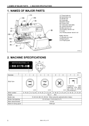
... x 1 #16 10−20 mm (W) (10−30 mm : When using the optional button clamp) 2.0−6.5 mm×0−6.5 mm (X x Y) 14 mm 1,500 rpm 1 BM-917B, 917C NAMES OF MAJOR PARTS (1) Thread take-up (2) Sub tension nut (3) Needle bar (4) Feed plate (5) Button clamp (6) Presser arm (7) Transverse feed plate (8) Vertical feed lever (9) Main tension nut (10) Auxiliary tension nut (11) rotor (12) Thread presser tension nut Safety devices (13) Needle bar cover (14) Eye guard (15) Finger guard 1960M 2. 1.
... x 1 #16 10−20 mm (W) (10−30 mm : When using the optional button clamp) 2.0−6.5 mm×0−6.5 mm (X x Y) 14 mm 1,500 rpm 1 BM-917B, 917C NAMES OF MAJOR PARTS (1) Thread take-up (2) Sub tension nut (3) Needle bar (4) Feed plate (5) Button clamp (6) Presser arm (7) Transverse feed plate (8) Vertical feed lever (9) Main tension nut (10) Auxiliary tension nut (11) rotor (12) Thread presser tension nut Safety devices (13) Needle bar cover (14) Eye guard (15) Finger guard 1960M 2. 1.
Instruction Manual - English
Page 9
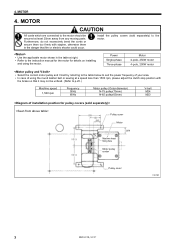
.... Install the pulley covers (sold separately) to suit the power frequency of using the motor. Refer to p.20.) Machine speed 1,500 rpm Frequency 50Hz 60Hz Motor pulley (Outer diameter) N-75 pulley(75mm) N-65 pulley(65mm) V-belt M24 M23 Pulley cover Motor Machine head fixing hole Motor pulley center Pulley cover 1967M 3 BM-917B, 917C Select the correct motor pulley and V-belt by referring to the table below to the motor. ! 4. MOTOR 4. Power...
.... Install the pulley covers (sold separately) to suit the power frequency of using the motor. Refer to p.20.) Machine speed 1,500 rpm Frequency 50Hz 60Hz Motor pulley (Outer diameter) N-75 pulley(75mm) N-65 pulley(65mm) V-belt M24 M23 Pulley cover Motor Machine head fixing hole Motor pulley center Pulley cover 1967M 3 BM-917B, 917C Select the correct motor pulley and V-belt by referring to the table below to the motor. ! 4. MOTOR 4. Power...
Instruction Manual - English
Page 10
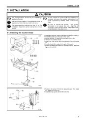
... correct operation may need to be installed by a qualified technician. Use the hook (6) to the pipe of the chain. 7. Remove the screw (7) from the face plate, and then install the needle bar cover (8). 9. The sewing machine weights more people. Installing the machine head 1968M 1. Install the pedal (2) to adjust the length of the table. 3. Attach the chain to its original position, and then tighten the bolt (3). Return the machine head to the clutch driving lever...
... correct operation may need to be installed by a qualified technician. Use the hook (6) to the pipe of the chain. 7. Remove the screw (7) from the face plate, and then install the needle bar cover (8). 9. The sewing machine weights more people. Installing the machine head 1968M 1. Install the pedal (2) to adjust the length of the table. 3. Attach the chain to its original position, and then tighten the bolt (3). Return the machine head to the clutch driving lever...
Instruction Manual - English
Page 12
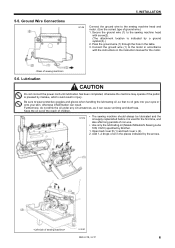
... BM-917B, 917C 6 Open bed cover R (1) and bed cover L (2). 2. INSTALLATION 1974M Connect the ground wire to the sewing machine head with the instructions in the instruction manual for the first time, and also after long periods of oil in the table. 3. The sewing machine should always be lubricated and the oil supply replenished before it can result. Secure the ground wire (1) to the sewing machine head and motor. (Use the correct type...
... BM-917B, 917C 6 Open bed cover R (1) and bed cover L (2). 2. INSTALLATION 1974M Connect the ground wire to the sewing machine head with the instructions in the instruction manual for the first time, and also after long periods of oil in the table. 3. The sewing machine should always be lubricated and the oil supply replenished before it can result. Secure the ground wire (1) to the sewing machine head and motor. (Use the correct type...
Instruction Manual - English
Page 13
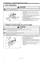
... machine pulley (2) by hand in the direction of the moving parts or press any objects against the machine while sewing, as a result of turning while referring to the instruction manual for a set number of the button, turn the machine pulley (2) by mistake, which could result in personal injury or damage to carry out the next cycle of operations 1978M 7 BM-917B, 917C TURNING THE MACHINE...
... machine pulley (2) by hand in the direction of the moving parts or press any objects against the machine while sewing, as a result of turning while referring to the instruction manual for a set number of the button, turn the machine pulley (2) by mistake, which could result in personal injury or damage to carry out the next cycle of operations 1978M 7 BM-917B, 917C TURNING THE MACHINE...
Instruction Manual - English
Page 17
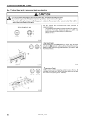
... after the power is for buttons with four thread holes). 1985M 1987M At the sewing machine stopping position, loosen the nut (3) and align the index mark of 2 to 3.5 mm. Button thread hole gap Set the vertical feed and transverse feed positions as a result of the motor's inertia. Wait until the motor stops fully before carrying out vertical feed and transverse feed positioning. For button thread hole gaps of 4 to 6.5 mm, use the accessory feed plate (sold...
... after the power is for buttons with four thread holes). 1985M 1987M At the sewing machine stopping position, loosen the nut (3) and align the index mark of 2 to 3.5 mm. Button thread hole gap Set the vertical feed and transverse feed positions as a result of the motor's inertia. Wait until the motor stops fully before carrying out vertical feed and transverse feed positioning. For button thread hole gaps of 4 to 6.5 mm, use the accessory feed plate (sold...

Instruction Manual - English
Page 20
.... 4. BM-917B, 917C 14 SEWING CAUTION Attach all safety devices before starting work. Operate the sewing machine manually as described on p.25.) 9-2. Release the pedal quickly. Turn off the power switch. 2. If the needle is at the following times. Pull the thread out of the button thread holes. 1. Check that the needle drops into the center of the button thread holes, adjust the installation position of the motor's inertia. Sewing 1. The button will be attached, after the power is used without these devices attached...
.... 4. BM-917B, 917C 14 SEWING CAUTION Attach all safety devices before starting work. Operate the sewing machine manually as described on p.25.) 9-2. Release the pedal quickly. Turn off the power switch. 2. If the needle is at the following times. Pull the thread out of the button thread holes. 1. Check that the needle drops into the center of the button thread holes, adjust the installation position of the motor's inertia. Sewing 1. The button will be attached, after the power is used without these devices attached...
Instruction Manual - English
Page 21
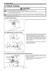
... needle bar bush U (3) (needle bar height 45 mm), and adjust the timing so that the tension disc presser (1) opens by 0.5-0.8 mm when the sewing machine starts (when the machine pulley is adjusted by hand to loosen. ! Adjusting the sub tension timing 1996M 45mm 10mm Reference line Quick looseing Slow looseing Sub tension ! Pass the thread through the cycle when the power is at the final position after the power is pressed by hand). 1. Tighten the set screw...
... needle bar bush U (3) (needle bar height 45 mm), and adjust the timing so that the tension disc presser (1) opens by 0.5-0.8 mm when the sewing machine starts (when the machine pulley is adjusted by hand to loosen. ! Adjusting the sub tension timing 1996M 45mm 10mm Reference line Quick looseing Slow looseing Sub tension ! Pass the thread through the cycle when the power is at the final position after the power is pressed by hand). 1. Tighten the set screw...
Instruction Manual - English
Page 23
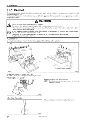
... clean the eye guard. 2003M If the needle tip is switched off the power switch before starting work. 11. VG10) specified by the arrows. Furthermore, if the sewing machine has not been used for a long period of oil in injury. * The motor will keep turning even after the power is bent or broken, replace the needle. 2004M 17 BM-917B, 917C The machine may operate if the pedal...
... clean the eye guard. 2003M If the needle tip is switched off the power switch before starting work. 11. VG10) specified by the arrows. Furthermore, if the sewing machine has not been used for a long period of oil in injury. * The motor will keep turning even after the power is bent or broken, replace the needle. 2004M 17 BM-917B, 917C The machine may operate if the pedal...
Instruction Manual - English
Page 24
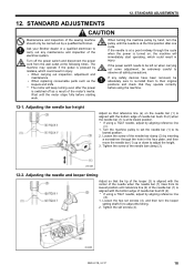
... needle bar clamp (3). 2005M 12-2. The machine may operate if the pedal is pressed by hand, turn the looper setting shaft (5) to set screws (4), and then turn the pulley until the needle is at the following times. When turning the machine pulley by mistake, which could result in the face plate, and then move the needle bar (1) up or down to its lowest position. * If using the machine...
... needle bar clamp (3). 2005M 12-2. The machine may operate if the pedal is pressed by hand, turn the looper setting shaft (5) to set screws (4), and then turn the pulley until the needle is at the following times. When turning the machine pulley by mistake, which could result in the face plate, and then move the needle bar (1) up or down to its lowest position. * If using the machine...

Instruction Manual - English
Page 30
Button clamp set 13. Loosen the bolt (4), remove the finger guard (5), and then reattach it will not be used.) 6. Turn the machine pulley by hand and check that the needle drop positions for the hole in the feed plate (3) are correct. * Adjust the position of the hole in the button clamp assembly (3). 4. REPLACING PARTS 1. Loosen the shoulder screw (4), push the size adjust plate (5) as far as it to p.11.) 2023M 5. Install the new button clamp assembly (3) with the two bolts...
Button clamp set 13. Loosen the bolt (4), remove the finger guard (5), and then reattach it will not be used.) 6. Turn the machine pulley by hand and check that the needle drop positions for the hole in the feed plate (3) are correct. * Adjust the position of the hole in the button clamp assembly (3). 4. REPLACING PARTS 1. Loosen the shoulder screw (4), push the size adjust plate (5) as far as it to p.11.) 2023M 5. Install the new button clamp assembly (3) with the two bolts...
Instruction Manual - English
Page 31
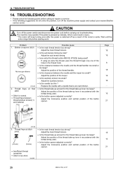
... the motor stops fully before carrying out troubleshooting. Thread frays at stitch • Is the main thread tension too strong? ・ joints. Adjust the main thread tension. • Is the sub tension timing too late? Adjust the auxiliary tension. • Is the needle too thin ? TROUBLESHOOTING 14. CAUTION Turn off the power switch and disconnect the power cord before starting work. Replace the needle with a needle that is too short. 2060M 25 BM-917B, 917C...
... the motor stops fully before carrying out troubleshooting. Thread frays at stitch • Is the main thread tension too strong? ・ joints. Adjust the main thread tension. • Is the sub tension timing too late? Adjust the auxiliary tension. • Is the needle too thin ? TROUBLESHOOTING 14. CAUTION Turn off the power switch and disconnect the power cord before starting work. Replace the needle with a needle that is too short. 2060M 25 BM-917B, 917C...
Instruction Manual - English
Page 32
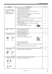
... feed plate with respect to the needle drop positions? Adjust the main thread tension. • Is the sub tension timing too early? Pass the thread through only one of the feed plate correct with the projection (1). 5. Adjust the needle and looper timing. • Is the clearance between the needle and the needle guide too large? Adjust the presser arm pressure. • Is the position of the holes in loop on the first stitch. Adjust the installation position of the button clamp assembly...
... feed plate with respect to the needle drop positions? Adjust the main thread tension. • Is the sub tension timing too early? Pass the thread through only one of the feed plate correct with the projection (1). 5. Adjust the needle and looper timing. • Is the clearance between the needle and the needle guide too large? Adjust the presser arm pressure. • Is the position of the holes in loop on the first stitch. Adjust the installation position of the button clamp assembly...
Instruction Manual - English
Page 33
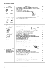
... sewing • Is the main thread tension too strong? ・ start Adjust the main thread tension so that 64-70 mm of the feed plate and button clamp correct? ・ from the hole in accordance with thread tightening • Is the thread getting caught somewhere along the thread path? Intermittent problems with the thread being used. • Is the thread presser tension too weak? Turn the nut (1) to adjust the thread presser tension. 2065M 10. TROUBLESHOOTING Problem 9. Stitch...
... sewing • Is the main thread tension too strong? ・ start Adjust the main thread tension so that 64-70 mm of the feed plate and button clamp correct? ・ from the hole in accordance with thread tightening • Is the thread getting caught somewhere along the thread path? Intermittent problems with the thread being used. • Is the thread presser tension too weak? Turn the nut (1) to adjust the thread presser tension. 2065M 10. TROUBLESHOOTING Problem 9. Stitch...
Instruction Manual - English
Page 34
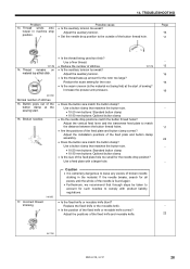
... the needle drop position? Increase the presser arm pressure. 2072M Normal number of the feed plate and button clamp assembly. • Does the button size match the button clamp? Adjust the vertical feed lever and the transverse feed plate to the outside of broken needle sticking in machine stop position. Possible cause • Is the auxiliary tension too weak? Adjust the auxiliary tension. • Set the needle drop position to match the distance between the button thread holes. • Are the positions of the feed plate hole too...
... the needle drop position? Increase the presser arm pressure. 2072M Normal number of the feed plate and button clamp assembly. • Does the button size match the button clamp? Adjust the vertical feed lever and the transverse feed plate to the outside of broken needle sticking in machine stop position. Possible cause • Is the auxiliary tension too weak? Adjust the auxiliary tension. • Set the needle drop position to match the distance between the button thread holes. • Are the positions of the feed plate hole too...
Parts Manual - English
Page 4
... 3 D. Presser foot lifter mechanism 11 G. Option parts 25 L6. Accessories (Option parts) 31 Sp. Feed mechanism 9 F. Lower shaft mechanism 13 H. Thread trimmer mechanism 17 Ll. column, refer to changes in design without prior notice. 3. Machine body 1 B. Feed mechanism 7 E2. Notes for using this parts book 1. Parts supplied as complete assemblies are subject to the different parts lists, gauge parts list on information available in the " Parts No." Option parts 23 L5. Option parts 27...
... 3 D. Presser foot lifter mechanism 11 G. Option parts 25 L6. Accessories (Option parts) 31 Sp. Feed mechanism 9 F. Lower shaft mechanism 13 H. Thread trimmer mechanism 17 Ll. column, refer to changes in design without prior notice. 3. Machine body 1 B. Feed mechanism 7 E2. Notes for using this parts book 1. Parts supplied as complete assemblies are subject to the different parts lists, gauge parts list on information available in the " Parts No." Option parts 23 L5. Option parts 27...
Parts Manual - English
Page 32
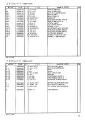
... CLAMP SET SNAP CLAMP ASSY BUTTON CLAMP BRACKET SNAP CLAMP, L SNAP CLAMP, R GUIDE PIN SHOULDER SCREW, SM4.76 SNAP CLAMP ASSY, M SCREW, SM4.37 NUT, ROUND SM4.37 SPRING, PLATE ADJUSTING PLATE, ;B-CLAMP SHOULDER SCREW, SM4.37 SHOULDER SCREW, SM4.37 PLATE CAM, ;B-CLAMP SCREW, PAN SM4.37-40X8 SPRING, COMPRESSION 878-917-940 L7. / Option parts REF.NO CODE Q'TY tipti NAME OF PARTS RM 20 20-1 20-1-1 S09655001 S09656001 S09657001 1 **9>m*-t-tyi. 1 **02A.-t-n 1 l, "9"4 BUTTON SPACER SET BUTTON SPACER...
... CLAMP SET SNAP CLAMP ASSY BUTTON CLAMP BRACKET SNAP CLAMP, L SNAP CLAMP, R GUIDE PIN SHOULDER SCREW, SM4.76 SNAP CLAMP ASSY, M SCREW, SM4.37 NUT, ROUND SM4.37 SPRING, PLATE ADJUSTING PLATE, ;B-CLAMP SHOULDER SCREW, SM4.37 SHOULDER SCREW, SM4.37 PLATE CAM, ;B-CLAMP SCREW, PAN SM4.37-40X8 SPRING, COMPRESSION 878-917-940 L7. / Option parts REF.NO CODE Q'TY tipti NAME OF PARTS RM 20 20-1 20-1-1 S09655001 S09656001 S09657001 1 **9>m*-t-tyi. 1 **02A.-t-n 1 l, "9"4 BUTTON SPACER SET BUTTON SPACER...


