SL2 wireless surround link - Owner's guide
Page 6
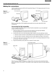
... Status LED SL2 transmitter Transmitter power pack (120V shown) Transmitter cable Surround speaker jacks When the power supply is plugged in, a Status LED on the back of the SL2 transmitter. 2. Figure 3 Different power supplies SL2 transmitter Input jack SL2 receiver Output jacks Figure 4 Transmitter connections Transmitter power pack AC power jack Receiver power pack AC power jack Before you plug...
... Status LED SL2 transmitter Transmitter power pack (120V shown) Transmitter cable Surround speaker jacks When the power supply is plugged in, a Status LED on the back of the SL2 transmitter. 2. Figure 3 Different power supplies SL2 transmitter Input jack SL2 receiver Output jacks Figure 4 Transmitter connections Transmitter power pack AC power jack Receiver power pack AC power jack Before you plug...
SL2 wireless surround link - Owner's guide
Page 7
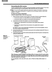
...: 1. Insert the RCA connectors into the jacks on the left. Surround sound speakers Status LED SL2 receiver AC power outlet Receiver power cord Surround speaker cables Receiver power pack When this power supply is placed on the back of the other , their LEDs turn orange. When the two are communicating...small jack labeled DC Power on the back of the receiver. 4. Note: To use the longer surround speaker cables that is plugged in "To adapt the surround speaker cable for Jewel Cube® speakers" on the right. • Insert the wire marked LR into a nearby AC (mains) outlet....
...: 1. Insert the RCA connectors into the jacks on the left. Surround sound speakers Status LED SL2 receiver AC power outlet Receiver power cord Surround speaker cables Receiver power pack When this power supply is placed on the back of the other , their LEDs turn orange. When the two are communicating...small jack labeled DC Power on the back of the receiver. 4. Note: To use the longer surround speaker cables that is plugged in "To adapt the surround speaker cable for Jewel Cube® speakers" on the right. • Insert the wire marked LR into a nearby AC (mains) outlet....
SL2 wireless surround link - Owner's guide
Page 9
...AC power outlet. • If it continues to blink red, check the cable connection between them does not intersect with large metal objects in the jacks. • Make sure the SL2 transmitter and receiver are not touching each side. Refer to the address sheet included in solving problems, contact Bose...and the SL2 receiver. Refer to "Making the connections" on page 6. • Make sure that cables are properly plugged into functioning AC power outlets. Make sure the connections are secure and the cable wires are no less than 61/2 feet (2 meters) and no more than 30 feet (9.2 meters...
...AC power outlet. • If it continues to blink red, check the cable connection between them does not intersect with large metal objects in the jacks. • Make sure the SL2 transmitter and receiver are not touching each side. Refer to the address sheet included in solving problems, contact Bose...and the SL2 receiver. Refer to "Making the connections" on page 6. • Make sure that cables are properly plugged into functioning AC power outlets. Make sure the connections are secure and the cable wires are no less than 61/2 feet (2 meters) and no more than 30 feet (9.2 meters...
Operating guide
Page 27
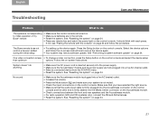
...the system. Follow the on the control console and select the device setup than optimum options. The Bose remote does not control a device I added during the initial setup • Try setting up the ...that you have selected the right source. • Make sure that the audio input cable is firmly plugged into the Acoustimass connector on the control console and the other end...Problem What to do anything • Make sure the AC power cord is inserted securely into the power supply. • Make sure the Acoustimass® module and the power supply are in the remote. • Reset the...
...the system. Follow the on the control console and select the device setup than optimum options. The Bose remote does not control a device I added during the initial setup • Try setting up the ...that you have selected the right source. • Make sure that the audio input cable is firmly plugged into the Acoustimass connector on the control console and the other end...Problem What to do anything • Make sure the AC power cord is inserted securely into the power supply. • Make sure the Acoustimass® module and the power supply are in the remote. • Reset the...
Installation guide
Page 6
... connector on the floor. Plug the other end of the power cord into the control console Power connector. Power AC power cord Power supply output cord Power supply 6. Acoustimass Module TAB 4 TAB 3 TAB 2 English 5. Remove a power cord from the power cord kit. 7. Leave the other end of the cable on the control console. Continue with the arrow on the next...
... connector on the floor. Plug the other end of the power cord into the control console Power connector. Power AC power cord Power supply output cord Power supply 6. Acoustimass Module TAB 4 TAB 3 TAB 2 English 5. Remove a power cord from the power cord kit. 7. Leave the other end of the cable on the control console. Continue with the arrow on the next...

Installation guide
Page 8
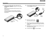
... faces the front of the audio input cable into the AC Power connector on the Acoustimass module. Plug the other end of the power cord into the Media Center connector on the Acoustimass module. Media Center TAB 4 TAB 3 TAB 2 English 4. AC Power 6. Make sure the flat surface with Kit... 3 on its front or back end. 3. Remove a power cord from the power cord kit. 5. Plug the free end of the module. TAB 8 TAB 7 SYSTEM SETUP ...
... faces the front of the audio input cable into the AC Power connector on the Acoustimass module. Plug the other end of the power cord into the Media Center connector on the Acoustimass module. Media Center TAB 4 TAB 3 TAB 2 English 4. AC Power 6. Make sure the flat surface with Kit... 3 on its front or back end. 3. Remove a power cord from the power cord kit. 5. Plug the free end of the module. TAB 8 TAB 7 SYSTEM SETUP ...


