Installation guide
Page 2
... flame sources, such as a CLASS 1 LASER PRODUCT according to the presence of uninsulated dangerous voltage within an equilateral triangle, is located on your LIFESTYLE® media center and Acoustimass® module enclosures: The lightning flash with arrowhead symbol, within the system enclosure that may result in any electronic products, use care not...
... flame sources, such as a CLASS 1 LASER PRODUCT according to the presence of uninsulated dangerous voltage within an equilateral triangle, is located on your LIFESTYLE® media center and Acoustimass® module enclosures: The lightning flash with arrowhead symbol, within the system enclosure that may result in any electronic products, use care not...

Installation guide
Page 3
...media center and the bottom panel of certain U.S. System: (circle one) LIFESTYLE® 18 system LIFESTYLE® 28 system LIFESTYLE® 38 system LIFESTYLE® 48 system Media center serial number Acoustimass module serial number Dealer name Dealer phone Purchase date Be sure to fill ... property rights owned by Macrovision Corporation. Use of this product. No part of this copyright protected technology is subject to Bose. MPEG Layer-3 audio compression technology licensed by Macrovision Corporation and other intellectual property rights owned by Fraunhofer IIS and THOMSON...
...media center and the bottom panel of certain U.S. System: (circle one) LIFESTYLE® 18 system LIFESTYLE® 28 system LIFESTYLE® 38 system LIFESTYLE® 48 system Media center serial number Acoustimass module serial number Dealer name Dealer phone Purchase date Be sure to fill ... property rights owned by Macrovision Corporation. Use of this product. No part of this copyright protected technology is subject to Bose. MPEG Layer-3 audio compression technology licensed by Macrovision Corporation and other intellectual property rights owned by Fraunhofer IIS and THOMSON...

Installation guide
Page 4
...your speakers 8 Left and right front speaker placement 8 Center speaker placement 9 Surround speaker placement 10 Acoustimass® module placement 10 Placing your media center 11 Connecting the speakers to the Acoustimass module 12 Connecting the plug-in cable to Jewel Cube® speakers 12 Making the two-wire ...connections for cube or cube array speakers 13 Connecting the Acoustimass module to the media center 15 Connecting the antennas 16 Connecting the FM antenna 16 Connecting the AM antenna 16 Connecting to a ...
...your speakers 8 Left and right front speaker placement 8 Center speaker placement 9 Surround speaker placement 10 Acoustimass® module placement 10 Placing your media center 11 Connecting the speakers to the Acoustimass module 12 Connecting the plug-in cable to Jewel Cube® speakers 12 Making the two-wire ...connections for cube or cube array speakers 13 Connecting the Acoustimass module to the media center 15 Connecting the antennas 16 Connecting the FM antenna 16 Connecting the AM antenna 16 Connecting to a ...
Installation guide
Page 5
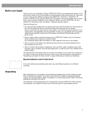
...The components included with each part of your media center, cube speakers, and Acoustimass® module. You will serve as a safe way to each part ...How to make a basic connection between your LIFESTYLE® system and your authorized Bose dealer immediately, or contact Bose directly. If any connections. There are ...LIFESTYLE® 18 Series II, LIFESTYLE® 28 Series II, LIFESTYLE® 38, and the LIFESTYLE® 48 systems. All include multiple room connections, most include the AdaptiQ® audio calibration system, and the LIFESTYLE® 38, and LIFESTYLE® 48...
...The components included with each part of your media center, cube speakers, and Acoustimass® module. You will serve as a safe way to each part ...How to make a basic connection between your LIFESTYLE® system and your authorized Bose dealer immediately, or contact Bose directly. If any connections. There are ...LIFESTYLE® 18 Series II, LIFESTYLE® 28 Series II, LIFESTYLE® 38, and the LIFESTYLE® 48 systems. All include multiple room connections, most include the AdaptiQ® audio calibration system, and the LIFESTYLE® 38, and LIFESTYLE® 48...
Installation guide
Page 6
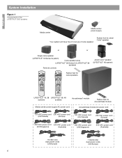
...174; speaker or or Single cube speaker (LIFESTYLE® 18 Series II system) Cube speaker array (LIFESTYLE® 28 Series II & LIFESTYLE® 38 systems) Remote controls Jewel Cube® speaker (LIFESTYLE® 48 system) On Off Mute All Mute CD&#... 0 uMusic Rating Similar Whole CD CD # Playlist Rubber feet for cube speakers LIFESTYLE® 18, 28 LIFESTYLE® 38, 48 systems systems Acoustimass® module Rubber feet for Acoustimass module Media center power supply AC power cord Acoustimass module AC power cord 120 VAC power cord 230 VAC power cord (US/Canada...
...174; speaker or or Single cube speaker (LIFESTYLE® 18 Series II system) Cube speaker array (LIFESTYLE® 28 Series II & LIFESTYLE® 38 systems) Remote controls Jewel Cube® speaker (LIFESTYLE® 48 system) On Off Mute All Mute CD&#... 0 uMusic Rating Similar Whole CD CD # Playlist Rubber feet for cube speakers LIFESTYLE® 18, 28 LIFESTYLE® 38, 48 systems systems Acoustimass® module Rubber feet for Acoustimass module Media center power supply AC power cord Acoustimass module AC power cord 120 VAC power cord 230 VAC power cord (US/Canada...
Installation guide
Page 8
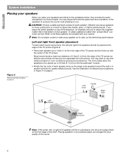
... for each speaker. If you . See the illustration of the sound. 8 Placing speakers in an enclosed space can cause speakers to the Bose address list included with your speakers according to create reflected sound. Left and right front speaker placement To best match sound and picture, the ...left , or right front speakers will be sure to 3 feet (1 m) from the picture. Bose recommends a maximum distance of 3 feet (1 m) from the Acoustimass® module. • Rotate the top cube of each speaker up to place them up to 20 feet (6.1 m) from the ...
... for each speaker. If you . See the illustration of the sound. 8 Placing speakers in an enclosed space can cause speakers to the Bose address list included with your speakers according to create reflected sound. Left and right front speaker placement To best match sound and picture, the ...left , or right front speakers will be sure to 3 feet (1 m) from the picture. Bose recommends a maximum distance of 3 feet (1 m) from the Acoustimass® module. • Rotate the top cube of each speaker up to place them up to 20 feet (6.1 m) from the ...
Installation guide
Page 9
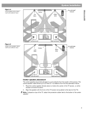
... speaker directly above or below the center of the picture. Figure 4 Cube speaker array placement and reflection rays Left front Center System Installation Right front Acoustimass® module English Figure 5 Single cube speaker placement and reflection rays Left surround Left front Center Right surround Right front...
... speaker directly above or below the center of the picture. Figure 4 Cube speaker array placement and reflection rays Left front Center System Installation Right front Acoustimass® module English Figure 5 Single cube speaker placement and reflection rays Left surround Left front Center Right surround Right front...
Installation guide
Page 10
Place the speakers at the listener. The longer the path from the listeners so that the grille with the Bose logo faces the room or is a good time to slide the Acoustimass module under a table or behind a cabinet. For further information, or to the address sheet included with the TV picture...sound output or creating too much bass. • For best bass performance, DO NOT place the Acoustimass module at the same end of the speaker array (or your local Bose® dealer or visit www.bose.com. Adjust the rear surround speakers to 50 feet (15.2 m) distance from the TV. Note...
Place the speakers at the listener. The longer the path from the listeners so that the grille with the Bose logo faces the room or is a good time to slide the Acoustimass module under a table or behind a cabinet. For further information, or to the address sheet included with the TV picture...sound output or creating too much bass. • For best bass performance, DO NOT place the Acoustimass module at the same end of the speaker array (or your local Bose® dealer or visit www.bose.com. Adjust the rear surround speakers to 50 feet (15.2 m) distance from the TV. Note...
Installation guide
Page 11
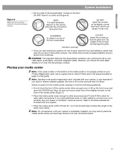
...sides. Placing your system. • Place the media center within 30 feet (9.1 m) of the Acoustimass module (the length of the audio input cable). Allow enough room to the Bose address list included with your media center Note: If the serial number on the bottom of the...the four self-adhesive rubber feet near the Acoustimass module. Note: For convenience, until your dealer or call Bose® customer service. English System Installation Figure 6 Right and wrong placements for the Acoustimass module • Put any side of the Acoustimass® module on its front grille end....
...sides. Placing your system. • Place the media center within 30 feet (9.1 m) of the Acoustimass module (the length of the audio input cable). Allow enough room to the Bose address list included with your media center Note: If the serial number on the bottom of the...the four self-adhesive rubber feet near the Acoustimass module. Note: For convenience, until your dealer or call Bose® customer service. English System Installation Figure 6 Right and wrong placements for the Acoustimass module • Put any side of the Acoustimass® module on its front grille end....
Installation guide
Page 12
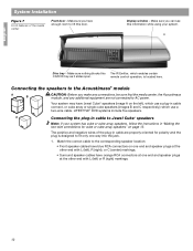
...the media center Front door - Make sure you make any connections, be sure that the media center, the Acoustimass module, and any additional equipment are properly oriented for cube or cube array speakers" on page 13. Make... sure nothing blocks this door. Connecting the speakers to the Acoustimass® module A B CAUTION: Before you can see this information while using your system has cube or cube array...7 Front features of the plug-in cable are not connected to AC power. LIFESTYLE® DVD systems include five speakers.
...the media center Front door - Make sure you make any connections, be sure that the media center, the Acoustimass module, and any additional equipment are properly oriented for cube or cube array speakers" on page 13. Make... sure nothing blocks this door. Connecting the speakers to the Acoustimass® module A B CAUTION: Before you can see this information while using your system has cube or cube array...7 Front features of the plug-in cable are not connected to AC power. LIFESTYLE® DVD systems include five speakers.
Installation guide
Page 13
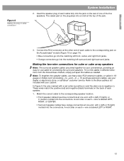
...front jacks. • Orange connectors go into a notch at one end, with your dealer or electronics store, or call Bose® customer service. to + and - Refer to the Bose address list included with L (left ) or R (right) molded into the connectors. Match the correct cable to the ... cube or cube array speakers Note: The surround speaker cables are joined together for your convenience, providing an easy-to the corresponding jack on the Acoustimass® module (Figure 10 on each cable fully into the connectors. In Figure 9, the wire marked with L (left ), R (right), or...
...front jacks. • Orange connectors go into a notch at one end, with your dealer or electronics store, or call Bose® customer service. to + and - Refer to the Bose address list included with L (left ) or R (right) molded into the connectors. Match the correct cable to the ... cube or cube array speakers Note: The surround speaker cables are joined together for your convenience, providing an easy-to the corresponding jack on the Acoustimass® module (Figure 10 on each cable fully into the connectors. In Figure 9, the wire marked with L (left ), R (right), or...
Installation guide
Page 14
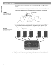
... left front, center, and right front jacks. • Plug the orange connectors into the black terminal. • Release the tab to place the Acoustimass module upside down while making connections. When done, place it more convenient to secure the wire. Connect each of the matching speaker. • Press... the terminal tab on either end or top. 14 Repeat this step for each cable to the Acoustimass module 3. Acoustimass module connector panel Note: You may find it on any of its sides but not on the back of the speaker and insert the...
... left front, center, and right front jacks. • Plug the orange connectors into the black terminal. • Release the tab to place the Acoustimass module upside down while making connections. When done, place it more convenient to secure the wire. Connect each of the matching speaker. • Press... the terminal tab on either end or top. 14 Repeat this step for each cable to the Acoustimass module 3. Acoustimass module connector panel Note: You may find it on any of its sides but not on the back of the speaker and insert the...
Installation guide
Page 15
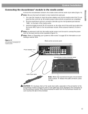
..., press the tab. Insert the telephone-style RJ-45 connector on the other end of the media center. 3. be sure to the Acoustimass module. Do not plug the other end into each connector is built into the jack, the connector locks in place. When disconnecting the ...sure to unwrap the power cord for information on the connection to press the tab on the Acoustimass module. English System Installation Connecting the Acoustimass® module to the media center Connect the Acoustimass module to other rooms" on page 32 for the best remote control operation (Figure 11). ...
..., press the tab. Insert the telephone-style RJ-45 connector on the other end of the media center. 3. be sure to the Acoustimass module. Do not plug the other end into each connector is built into the jack, the connector locks in place. When disconnecting the ...sure to unwrap the power cord for information on the connection to press the tab on the Acoustimass module. English System Installation Connecting the Acoustimass® module to the media center Connect the Acoustimass module to other rooms" on page 32 for the best remote control operation (Figure 11). ...

Installation guide
Page 16
... media center and other components as possible, at least 20 inches (50 cm), from the media center, and at least 2 feet (60 cm) from the Acoustimass® module. Move the AM loop antenna as far as possible. For best AM reception, turn the television off. Connecting to a cable radio provider Some...
... media center and other components as possible, at least 20 inches (50 cm), from the media center, and at least 2 feet (60 cm) from the Acoustimass® module. Move the AM loop antenna as far as possible. For best AM reception, turn the television off. Connecting to a cable radio provider Some...
Installation guide
Page 19
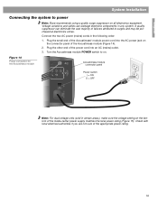
... not sure of the power cord into the AC power jack on the bottom of the Acoustimass module (Figure 14). 2. English System Installation Connecting the system to power Note: Bose recommends using a quality surge suppressor on . A quality suppressor can damage electronic components in ...and may be purchased at electronics stores. Plug the other end of the appropriate power rating. 19 Figure 14 Power connection for the Acoustimass module AUDIO INPUT Acoustimass module connector panel L C R OUTPUTSTO CUBE SPEAKERS FRONT SURROUND Power switch | = ON O = OFF L R POWER 100-...
... not sure of the power cord into the AC power jack on the bottom of the Acoustimass module (Figure 14). 2. English System Installation Connecting the system to power Note: Bose recommends using a quality surge suppressor on . A quality suppressor can damage electronic components in ...and may be purchased at electronics stores. Plug the other end of the appropriate power rating. 19 Figure 14 Power connection for the Acoustimass module AUDIO INPUT Acoustimass module connector panel L C R OUTPUTSTO CUBE SPEAKERS FRONT SURROUND Power switch | = ON O = OFF L R POWER 100-...

Installation guide
Page 22
...or significantly change the arrangement of the media center as shown below. Keep the headset and discs together in their instructions, the installation of your LIFESTYLE® DVD system is complete and its performance is tailored to turn on page 21 at any time. You may want to customize your system... to the placement of your system and your television. 2. Put on the connection panel of the room by relocating furniture, the speakers, or the Acoustimass® module. When Disc 2 indicates, connect the ADAPTiQ calibration headset to the AUX jacks on the headset so it to the...
...or significantly change the arrangement of the media center as shown below. Keep the headset and discs together in their instructions, the installation of your LIFESTYLE® DVD system is complete and its performance is tailored to turn on page 21 at any time. You may want to customize your system... to the placement of your system and your television. 2. Put on the connection panel of the room by relocating furniture, the speakers, or the Acoustimass® module. When Disc 2 indicates, connect the ADAPTiQ calibration headset to the AUX jacks on the headset so it to the...
Installation guide
Page 32
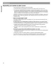
... to know: • Powered Acoustimass® 5 or Acoustimass 20 speakers require a variable RCA to take advantage of Bose® speakers and systems, using a Bose product you already own, if you can incorporate a variety of an advanced system capability. To properly connect and control additional speakers, you need : • Another LIFESTYLE® system remote control to...
... to know: • Powered Acoustimass® 5 or Acoustimass 20 speakers require a variable RCA to take advantage of Bose® speakers and systems, using a Bose product you already own, if you can incorporate a variety of an advanced system capability. To properly connect and control additional speakers, you need : • Another LIFESTYLE® system remote control to...
Installation guide
Page 35
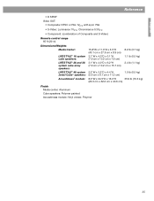
...; Component: (combination of Composite and S-Video) Remote control range 65 ft (20 m) Dimensions/Weights Media Center: LIFESTYLE® 18 system cube speakers: LIFESTYLE® 28 and 38 system cube array speakers: LIFESTYLE® 48 system Jewel Cube® speakers: Acoustimass® module: 15.8"W x 11.0"D x 3.5"H (40.1 cm x 27.9 cm x 8.9 cm) 3.1"W x 4.0"D x 3.1"H (7.9 cm x 10.2 cm x 7.9 cm) 3.1"W ... cm) 8.2 lb (3.7 kg) 1.1 lb (0.5 kg) 2.4 lb (1.1 kg) 1.0 lb (0.5 kg) 35.9 lb (16.3 kg) Finish Media center: Aluminum Cube speakers: Polymer painted Acoustimass module: Vinyl veneer, Polymer 35
...; Component: (combination of Composite and S-Video) Remote control range 65 ft (20 m) Dimensions/Weights Media Center: LIFESTYLE® 18 system cube speakers: LIFESTYLE® 28 and 38 system cube array speakers: LIFESTYLE® 48 system Jewel Cube® speakers: Acoustimass® module: 15.8"W x 11.0"D x 3.5"H (40.1 cm x 27.9 cm x 8.9 cm) 3.1"W x 4.0"D x 3.1"H (7.9 cm x 10.2 cm x 7.9 cm) 3.1"W ... cm) 8.2 lb (3.7 kg) 1.1 lb (0.5 kg) 2.4 lb (1.1 kg) 1.0 lb (0.5 kg) 35.9 lb (16.3 kg) Finish Media center: Aluminum Cube speakers: Polymer painted Acoustimass module: Vinyl veneer, Polymer 35
SL2 wireless surround link - Owner's guide
Page 4
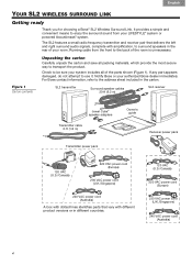
...power cord (U.K./Singapore) 240 VAC power cord (Australia) 4 If any part appears damaged, do not attempt to transport the product. Notify Bose or your system includes all packing materials, which provide the most secure way to use it. Figure 1 Carton contents Unpacking the carton ... immediately. Running cable from your room. Check to surround speakers in the carton. For Bose contact information, refer to the back of your LIFESTYLE® system or powered Acoustimass® system. It provides a simple and convenient means to enjoy the surround sound from the front ...
...power cord (U.K./Singapore) 240 VAC power cord (Australia) 4 If any part appears damaged, do not attempt to transport the product. Notify Bose or your system includes all packing materials, which provide the most secure way to use it. Figure 1 Carton contents Unpacking the carton ... immediately. Running cable from your room. Check to surround speakers in the carton. For Bose contact information, refer to the back of your LIFESTYLE® system or powered Acoustimass® system. It provides a simple and convenient means to enjoy the surround sound from the front ...
SL2 wireless surround link - Owner's guide
Page 5
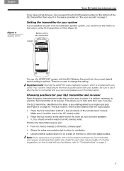
...at its receiver. This allows you to point the SL2 transmitter at the same end of an Acoustimass® speaker system, you need to "Troubleshooting" on how to deal with your LIFESTYLE® system, helps ensure the most accurate sound from view if you like. For further ... the SL2 is connected and your SL2 transmitter and receiver Radio frequency transmissions make this product easy to Other (Figure 2). Bottom of the Acoustimass® module. Make sure it in the space provided on "For your speakers are in the final position. Setting the transmitter for ventilation...
...at its receiver. This allows you to point the SL2 transmitter at the same end of an Acoustimass® speaker system, you need to "Troubleshooting" on how to deal with your LIFESTYLE® system, helps ensure the most accurate sound from view if you like. For further ... the SL2 is connected and your SL2 transmitter and receiver Radio frequency transmissions make this product easy to Other (Figure 2). Bottom of the Acoustimass® module. Make sure it in the space provided on "For your speakers are in the final position. Setting the transmitter for ventilation...


