Installation guide
Page 2
As with liquids, such as marked on your LIFESTYLE® media center and Acoustimass® module enclosures: The lightning flash with arrowhead symbol, within an equilateral triangle, is intended to alert the user to ...
As with liquids, such as marked on your LIFESTYLE® media center and Acoustimass® module enclosures: The lightning flash with arrowhead symbol, within an equilateral triangle, is intended to alert the user to ...

Installation guide
Page 3
... the bottom panel of the Acoustimass® module. Use of the U.S. System: (circle one) LIFESTYLE® 18 system LIFESTYLE® 28 system LIFESTYLE® 38 system LIFESTYLE® 48 system Media center serial number Acoustimass module serial number Dealer name Dealer phone Purchase date... Be sure to Bose. "Dolby" and the double-D symbol are trademarks of your product registration card ...
... the bottom panel of the Acoustimass® module. Use of the U.S. System: (circle one) LIFESTYLE® 18 system LIFESTYLE® 28 system LIFESTYLE® 38 system LIFESTYLE® 48 system Media center serial number Acoustimass module serial number Dealer name Dealer phone Purchase date... Be sure to Bose. "Dolby" and the double-D symbol are trademarks of your product registration card ...

Installation guide
Page 4
l E li h E i F Contents Where to add 32 How you make it all work together 33 Accessories 34 Limited warranty 34 Contacting customer service 34 Technical information 34 4 Safety Information 2 Introduction 5 Before you begin 5 Special indicator used in this book 5 Unpacking 5 System Installation 6 Cables and accessories 7 Placing your speakers 8 Left and right front speaker placement 8 Center speaker placement 9 Surround speaker placement 10 Acoustimass® module placement 10 Placing your media center 11 Connecting the speakers to the Acoustimass module 12 Connecting ...
l E li h E i F Contents Where to add 32 How you make it all work together 33 Accessories 34 Limited warranty 34 Contacting customer service 34 Technical information 34 4 Safety Information 2 Introduction 5 Before you begin 5 Special indicator used in this book 5 Unpacking 5 System Installation 6 Cables and accessories 7 Placing your speakers 8 Left and right front speaker placement 8 Center speaker placement 9 Surround speaker placement 10 Acoustimass® module placement 10 Placing your media center 11 Connecting the speakers to the Acoustimass module 12 Connecting ...
Installation guide
Page 5
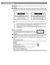
... the power cords. • How to make an even more versatile home theater system. Unpacking After unpacking your authorized Bose dealer immediately, or contact Bose directly. It will set the system up. First you will serve as the center of your home theater, providing superior...of your main room. You will identify and connect the cables that are four different systems, the LIFESTYLE® 18 Series II, LIFESTYLE® 28 Series II, LIFESTYLE® 38, and the LIFESTYLE® 48 systems. All include multiple room connections, most include the AdaptiQ® audio calibration system...
... the power cords. • How to make an even more versatile home theater system. Unpacking After unpacking your authorized Bose dealer immediately, or contact Bose directly. It will set the system up. First you will serve as the center of your home theater, providing superior...of your main room. You will identify and connect the cables that are four different systems, the LIFESTYLE® 18 Series II, LIFESTYLE® 28 Series II, LIFESTYLE® 38, and the LIFESTYLE® 48 systems. All include multiple room connections, most include the AdaptiQ® audio calibration system...
Installation guide
Page 6
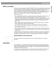
...for Jewel Cube® speaker or or Single cube speaker (LIFESTYLE® 18 Series II system) Cube speaker array (LIFESTYLE® 28 Series II & LIFESTYLE® 38 systems) Remote controls Jewel Cube® speaker (LIFESTYLE® 48 system) On Off Mute All Mute CD·... 3 4 5 6 7 8 9 Info Last 0 uMusic Rating Similar Whole CD CD # Playlist Rubber feet for cube speakers LIFESTYLE® 18, 28 LIFESTYLE® 38, 48 systems systems Acoustimass® module Rubber feet for Acoustimass module Media center power supply AC power cord Acoustimass module AC power cord...
...for Jewel Cube® speaker or or Single cube speaker (LIFESTYLE® 18 Series II system) Cube speaker array (LIFESTYLE® 28 Series II & LIFESTYLE® 38 systems) Remote controls Jewel Cube® speaker (LIFESTYLE® 48 system) On Off Mute All Mute CD·... 3 4 5 6 7 8 9 Info Last 0 uMusic Rating Similar Whole CD CD # Playlist Rubber feet for cube speakers LIFESTYLE® 18, 28 LIFESTYLE® 38, 48 systems systems Acoustimass® module Rubber feet for Acoustimass module Media center power supply AC power cord Acoustimass module AC power cord...
Installation guide
Page 7
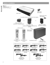
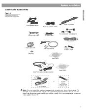
English Cables and accessories Figure 2 Cables and accessories included with your system System Installation L R Front speaker cables Surround speaker cables Audio input cable Stereo audio cable S-Video cable Two component video adapters FM antenna Video cable (6 ft) Batteries AM loop antenna IR emitter cable Setup disc 1 ADAPTiQ® audio calibration system Setup disc 2 Mounting strip TV on/off sensor or SCART adapter for 220-240V systems only Note: You may need three component video cables long enough to reach from your media center component video adapter to ...
English Cables and accessories Figure 2 Cables and accessories included with your system System Installation L R Front speaker cables Surround speaker cables Audio input cable Stereo audio cable S-Video cable Two component video adapters FM antenna Video cable (6 ft) Batteries AM loop antenna IR emitter cable Setup disc 1 ADAPTiQ® audio calibration system Setup disc 2 Mounting strip TV on/off sensor or SCART adapter for 220-240V systems only Note: You may need three component video cables long enough to reach from your media center component video adapter to ...
Installation guide
Page 8
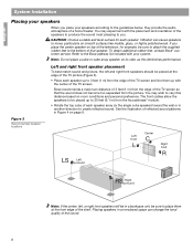
...speaker up with the center of that the sound does not become too separated from the picture. To obtain additional rubber feet, contact Bose® customer service. If you place the center speaker on room conditions and personal preference. See the illustration of the television, for ... glass, or highly polished wood. CAUTION: Choose a stable and level surface for example, be placed at the front edge of a home theater. Bose recommends a maximum distance of 3 feet (1 m) from the edge of the speakers to produce the sound most pleasing to the guidelines below, they ...
...speaker up with the center of that the sound does not become too separated from the picture. To obtain additional rubber feet, contact Bose® customer service. If you place the center speaker on room conditions and personal preference. See the illustration of the television, for ... glass, or highly polished wood. CAUTION: Choose a stable and level surface for example, be placed at the front edge of a home theater. Bose recommends a maximum distance of 3 feet (1 m) from the edge of the speakers to produce the sound most pleasing to the guidelines below, they ...
Installation guide
Page 9
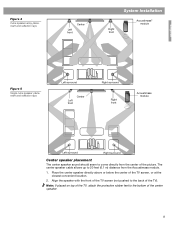
Place the center speaker directly above or below the center of the TV). The center speaker cable allows up to the bottom of the picture. Align the speaker with the front of the TV screen (not pushed to the back of the TV screen, or at the closest convenient location. 2. Figure 4 Cube speaker array placement and reflection rays Left front Center System Installation Right front Acoustimass® module English Figure 5 Single cube speaker placement and reflection rays Left surround Left front Center Right surround Right front Acoustimass module Left surround Right ...
Place the center speaker directly above or below the center of the TV). The center speaker cable allows up to the bottom of the picture. Align the speaker with the front of the TV screen (not pushed to the back of the TV screen, or at the closest convenient location. 2. Figure 4 Cube speaker array placement and reflection rays Left front Center System Installation Right front Acoustimass® module English Figure 5 Single cube speaker placement and reflection rays Left surround Left front Center Right surround Right front Acoustimass module Left surround Right ...
Installation guide
Page 10
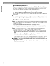
... still notice interference. • Place the Acoustimass module so that they cannot pinpoint the exact location of the sound source. Note: Bose offers a variety of sound around the listener. For further information, or to purchase accessories, contact your Product Registration card, now is... not already printed on your local Bose® dealer or visit www.bose.com. English System Installation Surround speaker placement The rear surround speakers create an area of speaker mounting accessories,...
... still notice interference. • Place the Acoustimass module so that they cannot pinpoint the exact location of the sound source. Note: Bose offers a variety of sound around the listener. For further information, or to purchase accessories, contact your Product Registration card, now is... not already printed on your local Bose® dealer or visit www.bose.com. English System Installation Surround speaker placement The rear surround speakers create an area of speaker mounting accessories,...
Installation guide
Page 11
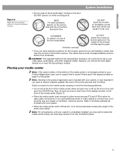
... Ventilation openings DO NOT stand the module on your Product Registration card, now is not a short-term risk to your dealer or call Bose® customer service. CAUTION: The magnetic field from scratches. The rubber feet provide increased stability and protection from the Acoustimass module is a... good time to tip over. Refer to Bose. Be sure to fill out the card and mail it on either end (Figure 6). DO NOT stand the module on its front ...
... Ventilation openings DO NOT stand the module on your Product Registration card, now is not a short-term risk to your dealer or call Bose® customer service. CAUTION: The magnetic field from scratches. The rubber feet provide increased stability and protection from the Acoustimass module is a... good time to tip over. Refer to Bose. Be sure to fill out the card and mail it on either end (Figure 6). DO NOT stand the module on its front ...
Installation guide
Page 12
... nothing blocks this The IR Emitter, which use a plug-in "Making the two-wire connections for polarity and the plug is located here. Display window - LIFESTYLE® DVD systems include five speakers. The positive and negative wires of the media center Front door -
... nothing blocks this The IR Emitter, which use a plug-in "Making the two-wire connections for polarity and the plug is located here. Display window - LIFESTYLE® DVD systems include five speakers. The positive and negative wires of the media center Front door -
Installation guide
Page 13
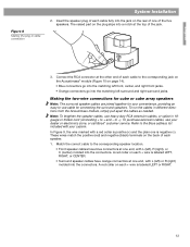
... RCA extension cables, or splice in different directions from the Acoustimass module, simply pull apart the cables as needed. Match the correct cable to the Bose address list included with L (left ) or R (right) molded into the connectors. These wires match the positive (red) and negative (black) terminals on each speaker. 1. A red... two-wire connections for cube or cube array speakers Note: The surround speaker cables are joined together for your dealer or electronics store, or call Bose® customer service.
... RCA extension cables, or splice in different directions from the Acoustimass module, simply pull apart the cables as needed. Match the correct cable to the Bose address list included with L (left ) or R (right) molded into the connectors. These wires match the positive (red) and negative (black) terminals on each speaker. 1. A red... two-wire connections for cube or cube array speakers Note: The surround speaker cables are joined together for your dealer or electronics store, or call Bose® customer service.
Installation guide
Page 14
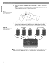
Connect each of the five speakers. Acoustimass module connector panel Note: You may find it on any of its sides but not on either end or top. 14 Repeat this step for each cable to the corresponding jack on the Acoustimass® module (Figure 10). • Plug the blue connectors into the matching left surround and right surround jacks. Connect the wire end of one speaker cable to cube speakers 2. When done, place it more convenient to the Acoustimass module 3. Front speakers Left Center Right Surround speakers Left Right FRONT L FRONT C FRONT R SURROUND L ...
Connect each of the five speakers. Acoustimass module connector panel Note: You may find it on any of its sides but not on either end or top. 14 Repeat this step for each cable to the corresponding jack on the Acoustimass® module (Figure 10). • Plug the blue connectors into the matching left surround and right surround jacks. Connect the wire end of one speaker cable to cube speakers 2. When done, place it more convenient to the Acoustimass module 3. Front speakers Left Center Right Surround speakers Left Right FRONT L FRONT C FRONT R SURROUND L ...
Installation guide
Page 15
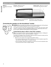
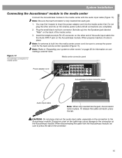
Plug the small black multi-pin connector (flat side up) into the media center power cord; To release the cable connector, press the tab. When disconnecting the cable from the Acoustimass module, be sure to insert the power adapter cord into the media center first. English System Installation Connecting the Acoustimass® module to the media center Connect the Acoustimass module to press the tab on the connector. 15 You may cause damage to other rooms" on page 32 for the best remote control operation (Figure 11). Note: An antenna is fully inserted into the jack, the ...
Plug the small black multi-pin connector (flat side up) into the media center power cord; To release the cable connector, press the tab. When disconnecting the cable from the Acoustimass module, be sure to insert the power adapter cord into the media center first. English System Installation Connecting the Acoustimass® module to the media center Connect the Acoustimass module to press the tab on the connector. 15 You may cause damage to other rooms" on page 32 for the best remote control operation (Figure 11). Note: An antenna is fully inserted into the jack, the ...

Installation guide
Page 16
Stand the loop antenna on the base, following the instructions enclosed with the orientation of the media center. Move the AM loop antenna as far as possible. Experiment with the AM antenna. 3. Note: Make sure that the cable radio installation includes a signal splitter so that only the FM radio band, not the cable TV band, is made to the FM antenna jack on a wall, follow the instructions enclosed with the antenna. Follow all safety instructions supplied with the antenna. 1. Connecting the AM antenna Note: To mount the AM antenna on the back panel of the loop for optimum AM ...
Stand the loop antenna on the base, following the instructions enclosed with the orientation of the media center. Move the AM loop antenna as far as possible. Experiment with the AM antenna. 3. Note: Make sure that the cable radio installation includes a signal splitter so that only the FM radio band, not the cable TV band, is made to the FM antenna jack on a wall, follow the instructions enclosed with the antenna. Follow all safety instructions supplied with the antenna. 1. Connecting the AM antenna Note: To mount the AM antenna on the back panel of the loop for optimum AM ...
Installation guide
Page 17
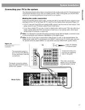
...This audio connection allows your TV to send sound to your system quickly. It may have a digital TV, you to view DVDs and see LIFESTYLE® system menus. This simple set of connections will find other options for connecting additional components to your TV allows, select Fixed in that ...VIDEO 1 input on the media center rear panel (Figure 12). • If the TV has both fixed (FIX) and variable (VAR) outputs, use your LIFESTYLE® system This video connection allows you may look different. Note: On the TV, be a single coaxial cable with the digital, to prevent a loss ...
...This audio connection allows your TV to send sound to your system quickly. It may have a digital TV, you to view DVDs and see LIFESTYLE® system menus. This simple set of connections will find other options for connecting additional components to your TV allows, select Fixed in that ...VIDEO 1 input on the media center rear panel (Figure 12). • If the TV has both fixed (FIX) and variable (VAR) outputs, use your LIFESTYLE® system This video connection allows you may look different. Note: On the TV, be a single coaxial cable with the digital, to prevent a loss ...
Installation guide
Page 18
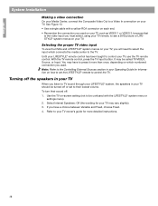
... numbered connection you used on your TV, such as VIDEO 1 or VIDEO 3, because that is the video input you listen to TV sound through your LIFESTYLE® system, the speakers in your Operating Guide for more than once, depending on your TV. Use the TV on how to set to their... sound off the speakers in your TV When you must select, using your TV remote, to see a DVD picture or LIFESTYLE® system menus on which connects the media center to control your TV, use the TV remote control. It may be confused with a yellow RCA...
... numbered connection you used on your TV, such as VIDEO 1 or VIDEO 3, because that is the video input you listen to TV sound through your LIFESTYLE® system, the speakers in your Operating Guide for more than once, depending on your TV. Use the TV on how to set to their... sound off the speakers in your TV When you must select, using your TV remote, to see a DVD picture or LIFESTYLE® system menus on which connects the media center to control your TV, use the TV remote control. It may be confused with a yellow RCA...
Installation guide
Page 19
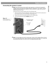
... system. Turn the Acoustimass module POWER switch to surges and may be purchased at electronics stores. English System Installation Connecting the system to power Note: Bose recommends using a quality surge suppressor on .
... system. Turn the Acoustimass module POWER switch to surges and may be purchased at electronics stores. English System Installation Connecting the system to power Note: Bose recommends using a quality surge suppressor on .
Installation guide
Page 20
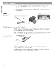
... closed. Figure 15 Power connection for details. 20 Alkaline batteries are recommended. Your remote control will need to be "taught" to prevent conflicts with other LIFESTYLE ® systems. Figure 16 Remote control battery installation Four (4) AAA (IEC-LR3) batteries + ++ + Battery compartment cover Replace all four batteries when the remote control stops...
... closed. Figure 15 Power connection for details. 20 Alkaline batteries are recommended. Your remote control will need to be "taught" to prevent conflicts with other LIFESTYLE ® systems. Figure 16 Remote control battery installation Four (4) AAA (IEC-LR3) batteries + ++ + Battery compartment cover Replace all four batteries when the remote control stops...
Installation guide
Page 21
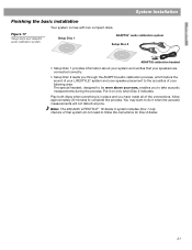
... speakers are connected correctly. • Setup Disc 2 leads you have made all of the connections. Note: The 220-240V LIFESTYLE ® 18 Series II system includes Disc 1 only. Owners of your LIFESTYLE® system and your system and verifies that system do it on only when Disc 2 indicates. English System Installation Finishing...
... speakers are connected correctly. • Setup Disc 2 leads you have made all of the connections. Note: The 220-240V LIFESTYLE ® 18 Series II system includes Disc 1 only. Owners of your LIFESTYLE® system and your system and verifies that system do it on only when Disc 2 indicates. English System Installation Finishing...
