The Bose® Lifestyle® amplifier - Owner's guide
Page 4
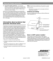
...provide reasonable protection against voltage surges and built-up static charges. This will not occur in a residential installation. Antenna grounding Example of cable entry as per National Electrical Code, ANSI/NFPA 70. These limits are encouraged to try to which can radiate radio frequency energy ... interference by turning the equipment off and on, you are designed to CATV system installer This reminder is practical. ©2001 Bose Corporation, The Mountain, Framingham, MA 01701-9168 USA 255805 AM Rev.00 JN10494 2b January 10, 2002 AM262840_00_V.pdf In particular...
...provide reasonable protection against voltage surges and built-up static charges. This will not occur in a residential installation. Antenna grounding Example of cable entry as per National Electrical Code, ANSI/NFPA 70. These limits are encouraged to try to which can radiate radio frequency energy ... interference by turning the equipment off and on, you are designed to CATV system installer This reminder is practical. ©2001 Bose Corporation, The Mountain, Framingham, MA 01701-9168 USA 255805 AM Rev.00 JN10494 2b January 10, 2002 AM262840_00_V.pdf In particular...
The Bose® Lifestyle® amplifier - Owner's guide
Page 6
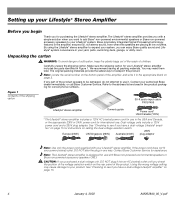
... Bose quality sound and Lifestyle® system convenience in any part of children. By using the Lifestyle® stereo amplifier to see if you have a dual voltage Lifestyle® amplifier" on the bottom panel of the shipping carton 30-ft audio input cable PN197406 Lifestyle&#...174; stereo amplifier Owner's guide Power cord* USA/Canada (120V) * The Lifestyle® stereo amplifier includes a 120V...
... Bose quality sound and Lifestyle® system convenience in any part of children. By using the Lifestyle® stereo amplifier to see if you have a dual voltage Lifestyle® amplifier" on the bottom panel of the shipping carton 30-ft audio input cable PN197406 Lifestyle&#...174; stereo amplifier Owner's guide Power cord* USA/Canada (120V) * The Lifestyle® stereo amplifier includes a 120V...
The Bose® Lifestyle® amplifier - Owner's guide
Page 7
...°C). • For optimum performance, place the amplifier in . (5.0 cm) • When mounting the amplifier on page 6 for your Lifestyle® stereo amplifier and mount it generates some heat. • DO NOT use the existing guide holes in a damp location. It is not... (2.5 m) of a power outlet. • Make sure that have hazards concealed behind them, such as the finished surface of the supplied 30-foot audio input cable. • Place the amplifier in order to be placed indoors. CAUTION: DO NOT mount the amplifier on boats. If adequate...
...°C). • For optimum performance, place the amplifier in . (5.0 cm) • When mounting the amplifier on page 6 for your Lifestyle® stereo amplifier and mount it generates some heat. • DO NOT use the existing guide holes in a damp location. It is not... (2.5 m) of a power outlet. • Make sure that have hazards concealed behind them, such as the finished surface of the supplied 30-foot audio input cable. • Place the amplifier in order to be placed indoors. CAUTION: DO NOT mount the amplifier on boats. If adequate...
The Bose® Lifestyle® amplifier - Owner's guide
Page 9
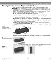
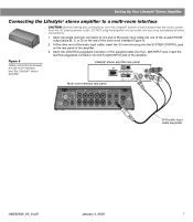
... end of the audio input cable into the L (left) INPUT jack. SPSEPAEKAEKREROOUUTPTUPUTSTS INPUT 30-ft audio input cable (supplied) AM262840_00_V.pdf January 4, 2002 7 Insert the red RCA piggyback connector into the R (right) INPUT jack of the supplied cable into one of the unused...interface (Figure 6). 2. Insert the white RCA piggyback connector of the amplifier. Figure 6 Cable connections between a multi-room interface and the Lifestyle® stereo amplifier Lifestyle® stereo amplifier rear panel Multi-room interface rear panel 4 Ω MINIMUM LL ...
... end of the audio input cable into the L (left) INPUT jack. SPSEPAEKAEKREROOUUTPTUPUTSTS INPUT 30-ft audio input cable (supplied) AM262840_00_V.pdf January 4, 2002 7 Insert the red RCA piggyback connector into the R (right) INPUT jack of the supplied cable into one of the unused...interface (Figure 6). 2. Insert the white RCA piggyback connector of the amplifier. Figure 6 Cable connections between a multi-room interface and the Lifestyle® stereo amplifier Lifestyle® stereo amplifier rear panel Multi-room interface rear panel 4 Ω MINIMUM LL ...
The Bose® Lifestyle® amplifier - Owner's guide
Page 11
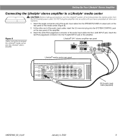
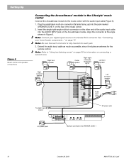
... SPEAKER ZONES 2 output jack on the rear panel of the media center (Figure 8). 2. At the other connections. 1. Figure 8 Cable connections between the Lifestyle® media center and the Lifestyle® stereo amplifier Lifestyle® SA-1 stereo amplifier rear panel Lifestyle® media center rear panel 30-ft audio input cable (supplied) AM262840_00_V.pdf January 4, 2002 9
... SPEAKER ZONES 2 output jack on the rear panel of the media center (Figure 8). 2. At the other connections. 1. Figure 8 Cable connections between the Lifestyle® media center and the Lifestyle® stereo amplifier Lifestyle® SA-1 stereo amplifier rear panel Lifestyle® media center rear panel 30-ft audio input cable (supplied) AM262840_00_V.pdf January 4, 2002 9
The Bose® Lifestyle® amplifier - Owner's guide
Page 13
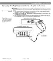
...64257;er. 3. Insert the red RCA piggyback connector into the R (right) INPUT jack of the supplied cable into the SPEAKER ZONES 2 output jack on the rear panel of the music center (Figure 10). 2. Lifestyle® stereo amplifier rear panel 4 Ω MINIMUM LL R L SYSTEM RR CONTROL L ... one end of the audio input cable into the L (left) INPUT jack. Insert the white RCA piggyback connector of the amplifier. At the other connections. 1. SPEAKER OUTPUTS INPUT Model 20 music center rear panel 30-ft audio input cable (supplied) AM262840_00_V.pdf January 4, 2002...
...64257;er. 3. Insert the red RCA piggyback connector into the R (right) INPUT jack of the supplied cable into the SPEAKER ZONES 2 output jack on the rear panel of the music center (Figure 10). 2. Lifestyle® stereo amplifier rear panel 4 Ω MINIMUM LL R L SYSTEM RR CONTROL L ... one end of the audio input cable into the L (left) INPUT jack. Insert the white RCA piggyback connector of the amplifier. At the other connections. 1. SPEAKER OUTPUTS INPUT Model 20 music center rear panel 30-ft audio input cable (supplied) AM262840_00_V.pdf January 4, 2002...
The Bose® Lifestyle® amplifier - Owner's guide
Page 15
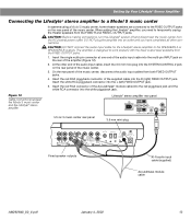
...12). 2. Insert the red RCA connector of the music center, disconnect the audio input cables from the FIXED OUTPUT jacks. 1. CAUTION: Before making connections, turn the Lifestyle® system off and disconnect the music center from the FIXED R and FIXED L ...2 ~ POWER 12VAC IN 1.0A ANTENNA SEE INSTRUCTION MANUAL Fixed speaker outputs 30-ft audio input cable (supplied) Acoustimass module cable AM262840_00_V.pdf January 4, 2002 13 Setting Up Your Lifestyle® Stereo Amplifier Connecting the Lifestyle® stereo amplifier to a Model 5 music center In systems...
...12). 2. Insert the red RCA connector of the music center, disconnect the audio input cables from the FIXED OUTPUT jacks. 1. CAUTION: Before making connections, turn the Lifestyle® system off and disconnect the music center from the FIXED R and FIXED L ...2 ~ POWER 12VAC IN 1.0A ANTENNA SEE INSTRUCTION MANUAL Fixed speaker outputs 30-ft audio input cable (supplied) Acoustimass module cable AM262840_00_V.pdf January 4, 2002 13 Setting Up Your Lifestyle® Stereo Amplifier Connecting the Lifestyle® stereo amplifier to a Model 5 music center In systems...
The Bose® Lifestyle® amplifier - Owner's guide
Page 16
...or black) terminal. For recommended wire sizes and lengths, see "Wire recommendations" on page 18. • Connect the right speaker cable to your Lifestyle® stereo amplifier CAUTION: DO NOT connect the amplifier to the negative (- Press the black terminal tab. ... tab. ON K40 l 2345678 Connecting speakers to your Lifestyle® system owner's guide for more information on the left speaker cable to the equipment. Speaker cable consists of any amplified music sources. Figure 14 Speaker cable connections on ). Doing so may cause damage to the...
...or black) terminal. For recommended wire sizes and lengths, see "Wire recommendations" on page 18. • Connect the right speaker cable to your Lifestyle® stereo amplifier CAUTION: DO NOT connect the amplifier to the negative (- Press the black terminal tab. ... tab. ON K40 l 2345678 Connecting speakers to your Lifestyle® system owner's guide for more information on the left speaker cable to the equipment. Speaker cable consists of any amplified music sources. Figure 14 Speaker cable connections on ). Doing so may cause damage to the...

The Bose® Lifestyle® amplifier - Owner's guide
Page 18
... is plugged into the FIXED OUTPUTs on . • If using a Model 5 music center for home theater (Lifestyle® 12 or Lifestyle® 8 systems), make sure the audio input cable is inserted into any openings. Do not allow liquids to do use a silicone caulking material, such as needed. It...to be connected to arrange for correct phone numbers. If the problem still exists, contact your Lifestyle® system after the wires are correct. If you have a problem operating your Bose dealer to the piggyback jacks on page 14. 16 January 4, 2002 AM262840_00_V.pdf Refer to ...
... is plugged into the FIXED OUTPUTs on . • If using a Model 5 music center for home theater (Lifestyle® 12 or Lifestyle® 8 systems), make sure the audio input cable is inserted into any openings. Do not allow liquids to do use a silicone caulking material, such as needed. It...to be connected to arrange for correct phone numbers. If the problem still exists, contact your Lifestyle® system after the wires are correct. If you have a problem operating your Bose dealer to the piggyback jacks on page 14. 16 January 4, 2002 AM262840_00_V.pdf Refer to ...
The Bose® Lifestyle® amplifier - Owner's guide
Page 19
... at the other end to the speaker on the right in your listening area. • Check the speaker cable connections to be sure no wires are using a Lifestyle® DVD system, the stereo amplifier will not work unless work at the other outputs on the...was connected to that speaker and the amplifier. Connect it to Bose. Choosing a lower setting should ensure continuous, even volume. Details of the problem. • Disconnect the same cable from that speaker. Warranty period The Lifestyle® stereo amplifier is • Check the speaker wire ...
... at the other end to the speaker on the right in your listening area. • Check the speaker cable connections to be sure no wires are using a Lifestyle® DVD system, the stereo amplifier will not work unless work at the other outputs on the...was connected to that speaker and the amplifier. Connect it to Bose. Choosing a lower setting should ensure continuous, even volume. Details of the problem. • Disconnect the same cable from that speaker. Warranty period The Lifestyle® stereo amplifier is • Check the speaker wire ...

Owner's guide
Page 4
... as is provided to call the CATV system installer's attention to grounding electrodes, and requirements for proper grounding. Antenna grounding Example of cable entry as contact with respect to proper grounding of the mast and supporting structure, grounding of the lead-in wire to an antenna ...Ground clamps Power service grounding electrode system (NEC ART 250, Part H) Note to CATV system installer This reminder is practical. ©2001 Bose Corporation, The Mountain, Framingham, MA 01701-9168 USA 255805 AM Rev.00 JN10494 2b October 28, 2001 AM197736_06_V.pdf Antenna lead in the ...
... as is provided to call the CATV system installer's attention to grounding electrodes, and requirements for proper grounding. Antenna grounding Example of cable entry as contact with respect to proper grounding of the mast and supporting structure, grounding of the lead-in wire to an antenna ...Ground clamps Power service grounding electrode system (NEC ART 250, Part H) Note to CATV system installer This reminder is practical. ©2001 Bose Corporation, The Mountain, Framingham, MA 01701-9168 USA 255805 AM Rev.00 JN10494 2b October 28, 2001 AM197736_06_V.pdf Antenna lead in the ...

Owner's guide
Page 6
... to prevent you to -use remote control Realism and impact Your Lifestyle® 30 Series II system is enhanced by a loud special effect (e.g., a crash or explosion). Look for purchasing the Bose® Lifestyle® 30 Series II system. Setting Up Before you begin Thank you for the terms ...Surround or Dolby Surround, or the symbol 3 on tapes and discs, or the word "surround" preceding a TV broadcast. • Stereo program material from DVD, digital TV, next-generation cable...
... to prevent you to -use remote control Realism and impact Your Lifestyle® 30 Series II system is enhanced by a loud special effect (e.g., a crash or explosion). Look for purchasing the Bose® Lifestyle® 30 Series II system. Setting Up Before you begin Thank you for the terms ...Surround or Dolby Surround, or the symbol 3 on tapes and discs, or the word "surround" preceding a TV broadcast. • Stereo program material from DVD, digital TV, next-generation cable...

Owner's guide
Page 7
...® CD magazine AM loop antenna Front speaker cables (blue connectors) FM antenna THE BOSE SPECIAL EDITION LIFESTYLE MUSIC SYSTEM CD ® Stereo cable Test CD Lifestyle® system CD * Power cord and pack ...Lifestyle® 30 Series II system: Acoustimass module • Lifestyle® music center • AC power (mains) pack* • FM antenna • AM loop antenna • Antenna base • Remote control • 3 AA batteries • Acoustimass module • 5 Jewel Cube® speakers • AC power (mains) cord* • Audio input cable • 5 speaker cables...
...® CD magazine AM loop antenna Front speaker cables (blue connectors) FM antenna THE BOSE SPECIAL EDITION LIFESTYLE MUSIC SYSTEM CD ® Stereo cable Test CD Lifestyle® system CD * Power cord and pack ...Lifestyle® 30 Series II system: Acoustimass module • Lifestyle® music center • AC power (mains) pack* • FM antenna • AM loop antenna • Antenna base • Remote control • 3 AA batteries • Acoustimass module • 5 Jewel Cube® speakers • AC power (mains) cord* • Audio input cable • 5 speaker cables...

Owner's guide
Page 8
... effect from the center of the picture, so that the sound does not become too separated from center, to come directly from your Lifestyle® 30 system (Figures 2 and 3). Center speaker The sound from the center speaker should seem to appear at the edge of the picture (...the locations for your Jewel Cube speakers. CAUTION: Choose a stable and level surface for your Lifestyle® 30 Series II system When you can change the tonal quality of the TV screen. The center speaker cable allows up to vary this diminishes performance by blocking the Jewel Cube ports. 1. Note: ...
... effect from the center of the picture, so that the sound does not become too separated from center, to come directly from your Lifestyle® 30 system (Figures 2 and 3). Center speaker The sound from the center speaker should seem to appear at the edge of the picture (...the locations for your Jewel Cube speakers. CAUTION: Choose a stable and level surface for your Lifestyle® 30 Series II system When you can change the tonal quality of the TV screen. The center speaker cable allows up to vary this diminishes performance by blocking the Jewel Cube ports. 1. Note: ...

Owner's guide
Page 9
... the sound source (Figure 3). Adjust the rear surround speakers to direct the sound to 50 feet (15.2 m) distance from the Acoustimass® module. The surround cables allow up to the front and back of sound around the listener. Figure 2 Recommended front speaker locations Left front Center ® Setting Up Right front...
... the sound source (Figure 3). Adjust the rear surround speakers to direct the sound to 50 feet (15.2 m) distance from the Acoustimass® module. The surround cables allow up to the front and back of sound around the listener. Figure 2 Recommended front speaker locations Left front Center ® Setting Up Right front...
Owner's guide
Page 10
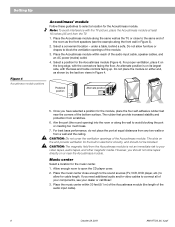
...45 cm) from a wall and the ceiling. under a table, behind a sofa. Place the Acoustimass module within 30 feet (9.1 m) of the Acoustimass module (the length of the audio input cable). 8 October 28, 2001 AM197736_06_V.pdf Do not place the module on the end provide ventilation for the Acoustimass module...® module Follow these guidelines to block the ventilation openings of the module. 3. Place the music center close to your dealer or call Bose®. 3. Place the Acoustimass module along the same wall as the TV, or close enough to the sound sources (TV, VCR, DVD...
...45 cm) from a wall and the ceiling. under a table, behind a sofa. Place the Acoustimass module within 30 feet (9.1 m) of the Acoustimass module (the length of the audio input cable). 8 October 28, 2001 AM197736_06_V.pdf Do not place the module on the end provide ventilation for the Acoustimass module...® module Follow these guidelines to block the ventilation openings of the module. 3. Place the music center close to your dealer or call Bose®. 3. Place the Acoustimass module along the same wall as the TV, or close enough to the sound sources (TV, VCR, DVD...
Owner's guide
Page 11
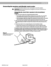
..., and right front jacks. Match the correct cable to the corresponding speaker location. • Front speaker cables have selected locations for your dealer or electronics store, or call Bose® customer service. Figure 5 Speaker cable connections to the Acoustimass® module 1. b. Setting Up Connecting the speakers and Lifestyle® music center Once you begin hooking...
..., and right front jacks. Match the correct cable to the corresponding speaker location. • Front speaker cables have selected locations for your dealer or electronics store, or call Bose® customer service. Figure 5 Speaker cable connections to the Acoustimass® module 1. b. Setting Up Connecting the speakers and Lifestyle® music center Once you begin hooking...
Owner's guide
Page 12
... home theater components..." Note: Refer to "Using two listening zones" on page 30 for the remote control. Setting Up Figure 6 Music center and speaker connections Connecting the Acoustimass® module to the Lifestyle® music center Connect the Acoustimass module to the female RCA connector. Right ...R TAPE OUT Multi-pin connector into each jack. 3. See "Connecting your digital signal source to the music center with the audio input cable (Figure 6). 1. Insert the single right-angle multi-pin connector on the other end of the music center. 2. on the rear of the...
... home theater components..." Note: Refer to "Using two listening zones" on page 30 for the remote control. Setting Up Figure 6 Music center and speaker connections Connecting the Acoustimass® module to the Lifestyle® music center Connect the Acoustimass module to the female RCA connector. Right ...R TAPE OUT Multi-pin connector into each jack. 3. See "Connecting your digital signal source to the music center with the audio input cable (Figure 6). 1. Insert the single right-angle multi-pin connector on the other end of the music center. 2. on the rear of the...
Owner's guide
Page 13
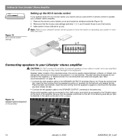
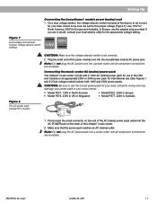
... or an appropriate 230V or 240V power pack for international use the adapter plug provided. Firmly insert the small connector on the end of the Lifestyle® music center. 2. Use 115V for North America; 230V for use in Australia 1. Using the wrong one may damage your power pack or your ...voltage (Figure 7). Plug the small end of the power (mains) cord into the AC POWER jack on the back of the AC (mains) power pack cable into the Acoustimass module AC power jack. Make sure that the power pack reaches an AC (mains) outlet. If you are complete. On a dual ...
... or an appropriate 230V or 240V power pack for international use the adapter plug provided. Firmly insert the small connector on the end of the Lifestyle® music center. 2. Use 115V for North America; 230V for use in Australia 1. Using the wrong one may damage your power pack or your ...voltage (Figure 7). Plug the small end of the power (mains) cord into the AC POWER jack on the back of the AC (mains) power pack cable into the Acoustimass module AC power jack. Make sure that the power pack reaches an AC (mains) outlet. If you are complete. On a dual ...
Owner's guide
Page 14
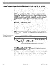
... a satellite decoder . In order for the Lifestyle® 30 system to 2 m) standard audio cable or video cable. Note: Line level outputs from encoded video tapes, you will need an adapter with your system selects the analog signal being sent to the AUX inputs. If your dealer or contact Bose®. Note: Ensure the connection between...
... a satellite decoder . In order for the Lifestyle® 30 system to 2 m) standard audio cable or video cable. Note: Line level outputs from encoded video tapes, you will need an adapter with your system selects the analog signal being sent to the AUX inputs. If your dealer or contact Bose®. Note: Ensure the connection between...


