The Bose® Lifestyle® amplifier - Owner's guide
Page 6
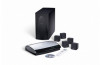
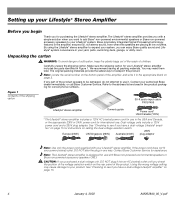
...Bose Customer Service for correct phone numbers. Note: The Lifestyle® stereo amplifier is designed for purchasing the Lifestyle® stereo amplifier. Make sure the shipping carton for your system, you check the position of the shipping carton 30-ft audio input cable PN197406 Lifestyle...® stereo amplifier Owner's guide Power cord* USA/Canada (120V) * The Lifestyle® stereo amplifier includes a 120V AC (mains) power cord for use...
...Bose Customer Service for correct phone numbers. Note: The Lifestyle® stereo amplifier is designed for purchasing the Lifestyle® stereo amplifier. Make sure the shipping carton for your system, you check the position of the shipping carton 30-ft audio input cable PN197406 Lifestyle...® stereo amplifier Owner's guide Power cord* USA/Canada (120V) * The Lifestyle® stereo amplifier includes a 120V AC (mains) power cord for use...
The Bose® Lifestyle® amplifier - Owner's guide
Page 7
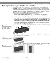
...fier on surfaces that are not sturdy enough, or that the amplifier is located within the reach of the supplied 30-foot audio input cable. • Place the amplifier in an area where the maximum ambient temperature is installed on a shelf, or in a bookcase,... a floor or shelf (Figure 3), the amplifier's rubber feet provide stability and prevent scratches. Setting Up Your Lifestyle® Stereo Amplifier Selecting a location for your Lifestyle® stereo amplifier Select a location for your amplifier: • Locate the amplifier indoors and ...
...fier on surfaces that are not sturdy enough, or that the amplifier is located within the reach of the supplied 30-foot audio input cable. • Place the amplifier in an area where the maximum ambient temperature is installed on a shelf, or in a bookcase,... a floor or shelf (Figure 3), the amplifier's rubber feet provide stability and prevent scratches. Setting Up Your Lifestyle® Stereo Amplifier Selecting a location for your Lifestyle® stereo amplifier Select a location for your amplifier: • Locate the amplifier indoors and ...
The Bose® Lifestyle® amplifier - Owner's guide
Page 9
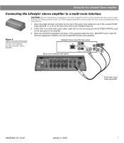
... the rear of the amplifier. Insert the white RCA piggyback connector of the amplifier. 3. SPSEPAEKAEKREROOUUTPTUPUTSTS INPUT 30-ft audio input cable (supplied) AM262840_00_V.pdf January 4, 2002 7 Setting Up Your Lifestyle® Stereo Amplifier Connecting the Lifestyle® stereo amplifier to a multi-room interface CAUTION: Before making any connections, turn the...
... the rear of the amplifier. Insert the white RCA piggyback connector of the amplifier. 3. SPSEPAEKAEKREROOUUTPTUPUTSTS INPUT 30-ft audio input cable (supplied) AM262840_00_V.pdf January 4, 2002 7 Setting Up Your Lifestyle® Stereo Amplifier Connecting the Lifestyle® stereo amplifier to a multi-room interface CAUTION: Before making any connections, turn the...
The Bose® Lifestyle® amplifier - Owner's guide
Page 11
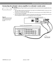
... you have completed all other end of the amplifier. Figure 8 Cable connections between the Lifestyle® media center and the Lifestyle® stereo amplifier Lifestyle® SA-1 stereo amplifier rear panel Lifestyle® media center rear panel 30-ft audio input cable (supplied) AM262840_00_V.pdf January 4, 2002 9 DO NOT plug the amplifier...
... you have completed all other end of the amplifier. Figure 8 Cable connections between the Lifestyle® media center and the Lifestyle® stereo amplifier Lifestyle® SA-1 stereo amplifier rear panel Lifestyle® media center rear panel 30-ft audio input cable (supplied) AM262840_00_V.pdf January 4, 2002 9 DO NOT plug the amplifier...
The Bose® Lifestyle® amplifier - Owner's guide
Page 13
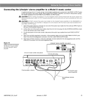
...panel of the supplied cable into the R (right) INPUT jack of the amplifier. 3. Insert the single multi-pin connector at one end of the audio input cable into the SPEAKER ZONES 2 output jack on the rear panel of the amplifier. Lifestyle® stereo ampli&#...64257;er rear panel 4 Ω MINIMUM LL R L SYSTEM RR CONTROL L R +- Setting Up Your Lifestyle® Stereo Amplifier Connecting the Lifestyle® stereo amplifi...
...panel of the supplied cable into the R (right) INPUT jack of the amplifier. 3. Insert the single multi-pin connector at one end of the audio input cable into the SPEAKER ZONES 2 output jack on the rear panel of the amplifier. Lifestyle® stereo ampli&#...64257;er rear panel 4 Ω MINIMUM LL R L SYSTEM RR CONTROL L R +- Setting Up Your Lifestyle® Stereo Amplifier Connecting the Lifestyle® stereo amplifi...
The Bose® Lifestyle® amplifier - Owner's guide
Page 15
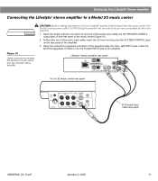
...FIXED OUTPUT jacks. 1. Insert the white RCA piggyback connector into the R (right) FIXED OUTPUT jack. CAUTION: DO NOT connect the audio input cable for the Lifestyle® stereo amplifier to the FIXED OUTPUT jacks on the rear panel of the music center. Setting Up Your...3. Insert the single multi-pin connector at one end of the music center, disconnect the audio input cables from the AC (mains) power outlet. At the other connections. CAUTION: Before making connections, turn the Lifestyle® system off and disconnect the music center from both FIXED OUTPUT jacks. 4. On ...
...FIXED OUTPUT jacks. 1. Insert the white RCA piggyback connector into the R (right) FIXED OUTPUT jack. CAUTION: DO NOT connect the audio input cable for the Lifestyle® stereo amplifier to the FIXED OUTPUT jacks on the rear panel of the music center. Setting Up Your...3. Insert the single multi-pin connector at one end of the music center, disconnect the audio input cables from the AC (mains) power outlet. At the other connections. CAUTION: Before making connections, turn the Lifestyle® system off and disconnect the music center from both FIXED OUTPUT jacks. 4. On ...

The Bose® Lifestyle® amplifier - Owner's guide
Page 18
... the product packaging for home theater (Lifestyle® 12 or Lifestyle® 8 systems), make sure the amplifier audio input cable is plugged into any headphones. • Make sure the remote control switch settings are firmly connected at hardware stores. If the problem still exists, contact your Bose dealer to the address list enclosed...
... the product packaging for home theater (Lifestyle® 12 or Lifestyle® 8 systems), make sure the amplifier audio input cable is plugged into any headphones. • Make sure the remote control switch settings are firmly connected at hardware stores. If the problem still exists, contact your Bose dealer to the address list enclosed...

Owner's guide
Page 41
... inserted securely into the Acoustimass® module, and the power pack and power cord are recommended. 1. symbols on the back of the remote (Figure 18). 2. Slide the battery compartment cover back into operating AC wall outlets. • Be sure to restore communication between the media center and the speakers... for any external components. If it is, press the Mute button on the remote control to unmute the sound. • Make sure the audio input cable is firmly seated in the media center SPEAKER ZONE 1 jack and the multi-pin connector on the other end is firmly seated...
... inserted securely into the Acoustimass® module, and the power pack and power cord are recommended. 1. symbols on the back of the remote (Figure 18). 2. Slide the battery compartment cover back into operating AC wall outlets. • Be sure to restore communication between the media center and the speakers... for any external components. If it is, press the Mute button on the remote control to unmute the sound. • Make sure the audio input cable is firmly seated in the media center SPEAKER ZONE 1 jack and the multi-pin connector on the other end is firmly seated...

Owner's guide
Page 43
... to reduce interference. Media center display says: • Make sure the audio input cable is noisy in sur- • Weak FM stations will produce static in the media center NOT CONNECTED SPEAKER ZONE 1 jack. See "Programming your LIFESTYLE® remote to control not control your TV, VCR, your password •...on the back of your TV. • Verify that the front of the media center. cable/satellite box, or • Make sure that the TV on/off detector on your LIFESTYLE® Installation Guide. Your TV turns on and off unexpectedly. • Reposition the TV ...
... to reduce interference. Media center display says: • Make sure the audio input cable is noisy in sur- • Weak FM stations will produce static in the media center NOT CONNECTED SPEAKER ZONE 1 jack. See "Programming your LIFESTYLE® remote to control not control your TV, VCR, your password •...on the back of your TV. • Verify that the front of the media center. cable/satellite box, or • Make sure that the TV on/off detector on your LIFESTYLE® Installation Guide. Your TV turns on and off unexpectedly. • Reposition the TV ...

Installation guide
Page 6
... Installation Cables and accessories The following items are included with your LIFESTYLE® system. Figure 2 Cables and accessories included with your system Surround speaker cables Front speaker cables Stereo audio cable Video cable (6 ft) S-Video cable Audio input cable Component ...cable ADAPTiQ™ audio calibration system* Media center power supply Batteries Rubber feet for Acoustimass® module Rubber feet for cube speakers Setup disc 2 Remote control Setup disc 1 Media center power supply AC power cord ADAPTiQ™ headset * May not be included with your Bose...
... Installation Cables and accessories The following items are included with your LIFESTYLE® system. Figure 2 Cables and accessories included with your system Surround speaker cables Front speaker cables Stereo audio cable Video cable (6 ft) S-Video cable Audio input cable Component ...cable ADAPTiQ™ audio calibration system* Media center power supply Batteries Rubber feet for Acoustimass® module Rubber feet for cube speakers Setup disc 2 Remote control Setup disc 1 Media center power supply AC power cord ADAPTiQ™ headset * May not be included with your Bose...

Installation guide
Page 9
... the front grille. See Figure 5. DO NOT stand the module on or near the corners of the audio input cable, speaker cables, and an AC power (mains) outlet. • Place the Acoustimass module on the floor ...you have selected a position for the built-in the space provided on the long edge, with the Bose® emblem faces into the room or along the same wall as the TV, or close to ...creating too much bass. • For best bass performance, DO NOT place the Acoustimass module at least 18 inches (45 cm) from scratches. DO NOT stand the module on its long edge or lay it...
... the front grille. See Figure 5. DO NOT stand the module on or near the corners of the audio input cable, speaker cables, and an AC power (mains) outlet. • Place the Acoustimass module on the floor ...you have selected a position for the built-in the space provided on the long edge, with the Bose® emblem faces into the room or along the same wall as the TV, or close to ...creating too much bass. • For best bass performance, DO NOT place the Acoustimass module at least 18 inches (45 cm) from scratches. DO NOT stand the module on its long edge or lay it...

Installation guide
Page 10
...number on the bottom of the CD/DVD player. Make sure you allow for you to AC power. Refer to the Bose address list included with your dealer or call Bose® customer service. Make sure nothing blocks this guide. In Figure 7, the wire marked with your system is negative ..., the Acoustimass module, and any additional equipment are joined together for the media center, keeping in the space provided on the back of the audio input cable). Select a location for your warranty card and in mind the following guidelines: • Do not block the front of this tray as needed...
...number on the bottom of the CD/DVD player. Make sure you allow for you to AC power. Refer to the Bose address list included with your dealer or call Bose® customer service. Make sure nothing blocks this guide. In Figure 7, the wire marked with your system is negative ..., the Acoustimass module, and any additional equipment are joined together for the media center, keeping in the space provided on the back of the audio input cable). Select a location for your warranty card and in mind the following guidelines: • Do not block the front of this tray as needed...

Installation guide
Page 11
...the orange connectors into the matching left ), R (right), or C (center) molded into the connectors. Front speaker cables have orange connectors at one end, with L (left front, center, and right front jacks. Connect each of the matching ...English Figure 7 Connecting speaker cables to the cube speakers Terminal tab System Installation Red (+) wire Figure 8 Speaker connections to the corresponding speaker location. Front speakers Left Center Right Surround speakers Left Right FRONT L FRONT C FRONT R SURROUND L SURROUND R AUDIO INPUT OUTPUTS TO CUBE SPEAKERS FRONT ...
...the orange connectors into the matching left ), R (right), or C (center) molded into the connectors. Front speaker cables have orange connectors at one end, with L (left front, center, and right front jacks. Connect each of the matching ...English Figure 7 Connecting speaker cables to the cube speakers Terminal tab System Installation Red (+) wire Figure 8 Speaker connections to the corresponding speaker location. Front speakers Left Center Right Surround speakers Left Right FRONT L FRONT C FRONT R SURROUND L SURROUND R AUDIO INPUT OUTPUTS TO CUBE SPEAKERS FRONT ...

Installation guide
Page 12
Insert the telephone-style RJ-45 connector on the other end of the audio input cable into each connector is fully inserted into the AUDIO INPUT jack on the back of the media center. 2. Audio input cable Note: Press tab to media center TV SENSOR IR EMITTER SERIAL DATA 33V DC POWER 1.1A ... When fully inserted into the SPEAKER ZONES jack labeled "1" on the Acoustimass module. CAUTION: Do not place strain on the audio input cable, especially on the connector. 12 English System Installation Connecting the Acoustimass® module to the media center Connect the Acoustimass module...
Insert the telephone-style RJ-45 connector on the other end of the audio input cable into each connector is fully inserted into the AUDIO INPUT jack on the back of the media center. 2. Audio input cable Note: Press tab to media center TV SENSOR IR EMITTER SERIAL DATA 33V DC POWER 1.1A ... When fully inserted into the SPEAKER ZONES jack labeled "1" on the Acoustimass module. CAUTION: Do not place strain on the audio input cable, especially on the connector. 12 English System Installation Connecting the Acoustimass® module to the media center Connect the Acoustimass module...

Installation guide
Page 13
...VCR TV AM L L L L L FM 75 ANTENNA 1 OPTICAL OPTICAL R R R R R VIDEO INPUTS COMPOSITE S-VIDEO 2 SPEAKER ZONES INPUT OUTPUT DIGITAL AUDIO OUTPUTS DIGITAL DIGITAL DIGITAL AUDIO INPUTS DIGITAL COMPOSITE S-VIDEO VIDEO OUTPUTS Connecting an FM antenna Plug the connector on a wall, follow the instructions enclosed...To install an outdoor antenna, consult a qualified installer. Connecting to a cable radio provider Some cable TV providers make FM radio signals available through the cable service to ensure the best reception. This connection is received by the media center...
...VCR TV AM L L L L L FM 75 ANTENNA 1 OPTICAL OPTICAL R R R R R VIDEO INPUTS COMPOSITE S-VIDEO 2 SPEAKER ZONES INPUT OUTPUT DIGITAL AUDIO OUTPUTS DIGITAL DIGITAL DIGITAL AUDIO INPUTS DIGITAL COMPOSITE S-VIDEO VIDEO OUTPUTS Connecting an FM antenna Plug the connector on a wall, follow the instructions enclosed...To install an outdoor antenna, consult a qualified installer. Connecting to a cable radio provider Some cable TV providers make FM radio signals available through the cable service to ensure the best reception. This connection is received by the media center...

Installation guide
Page 14
... VIDEO IN TV R L 14 Component video consists of your TV (Figure 12). Making audio connections Using the supplied stereo audio cable, connect the left (L) and right (R) audio outputs on the rear panel of your TV to the L and R TV audio inputs on the rear panel of three separate video signals (Y, Pb, and Pr) which deliver a very...
... VIDEO IN TV R L 14 Component video consists of your TV (Figure 12). Making audio connections Using the supplied stereo audio cable, connect the left (L) and right (R) audio outputs on the rear panel of your TV to the L and R TV audio inputs on the rear panel of three separate video signals (Y, Pb, and Pr) which deliver a very...

Installation guide
Page 15
See your LIFESTYLE® 18 system operating guide for instructions on how to change the video output setting to your LIFESTYLE® system, contact your local electronics store or authorized Bose dealer. Media Center S-VIDEO OUTPUT COMPOSITE VIDEO OUTPUT Component video adapter Your TV Pr (Red) Y (Green) Pb... the color-coded connections with the stereo audio and video cables required to connect it to the L and R VCR audio inputs on the rear panel of the media center provides audio and video connections for the Y, Pb, and Pr jacks and the Bose® component video adapter (Figure 12...
See your LIFESTYLE® 18 system operating guide for instructions on how to change the video output setting to your LIFESTYLE® system, contact your local electronics store or authorized Bose dealer. Media Center S-VIDEO OUTPUT COMPOSITE VIDEO OUTPUT Component video adapter Your TV Pr (Red) Y (Green) Pb... the color-coded connections with the stereo audio and video cables required to connect it to the L and R VCR audio inputs on the rear panel of the media center provides audio and video connections for the Y, Pb, and Pr jacks and the Bose® component video adapter (Figure 12...

Installation guide
Page 16
... box output to the COMPOSITE VIDEO INPUT. Figure 14 Media center-to-cable/satellite box video and audio connections (if VCR not used with your cable/satellite box, if you choose to connect it to your LIFESTYLE® system, contact your local electronics store or authorized Bose dealer. Note: If your cable/satellite box did not come...
... box output to the COMPOSITE VIDEO INPUT. Figure 14 Media center-to-cable/satellite box video and audio connections (if VCR not used with your cable/satellite box, if you choose to connect it to your LIFESTYLE® system, contact your local electronics store or authorized Bose dealer. Note: If your cable/satellite box did not come...

Installation guide
Page 17
... L L FM 75 ANTENNA 1 OPTICAL OPTICAL R R R R R VIDEO INPUTS COMPOSITE S-VIDEO 2 SPEAKER ZONES INPUT OUTPUT DIGITAL AUDIO OUTPUTS DIGITAL DIGITAL DIGITAL AUDIO INPUTS DIGITAL COMPOSITE S-VIDEO VIDEO OUTPUTS TV SENSOR jack Note: If you have a ...back of the media center. 2. Position the TV on/off detector" in your LIFESTYLE® Operating Guide. Note: DO NOT use the sensor, you will not work...detector on separately each time it is needed , when another video source (DVD, cable/satellite box, etc.) is working properly from this location. You can determine that the...
... L L FM 75 ANTENNA 1 OPTICAL OPTICAL R R R R R VIDEO INPUTS COMPOSITE S-VIDEO 2 SPEAKER ZONES INPUT OUTPUT DIGITAL AUDIO OUTPUTS DIGITAL DIGITAL DIGITAL AUDIO INPUTS DIGITAL COMPOSITE S-VIDEO VIDEO OUTPUTS TV SENSOR jack Note: If you have a ...back of the media center. 2. Position the TV on/off detector" in your LIFESTYLE® Operating Guide. Note: DO NOT use the sensor, you will not work...detector on separately each time it is needed , when another video source (DVD, cable/satellite box, etc.) is working properly from this location. You can determine that the...

Installation guide
Page 23
... Connect the audio input cable from one or two sound sources (such as zone 1. Note: For zone 2, use only cables that is compatible with your home entertainment system. Cables marked "VAR" should not be connected (special adapter required). • The appropriate LIFESTYLE® system cable to connect ...speakers, you are ready to set up a speaker system in a second zone? 1. English Reference Setting up a second zone? • A Bose® powered speaker system that have a mini-DIN connector marked "FIX". Each listening area, whether a room or a group of the media center...
... Connect the audio input cable from one or two sound sources (such as zone 1. Note: For zone 2, use only cables that is compatible with your home entertainment system. Cables marked "VAR" should not be connected (special adapter required). • The appropriate LIFESTYLE® system cable to connect ...speakers, you are ready to set up a speaker system in a second zone? 1. English Reference Setting up a second zone? • A Bose® powered speaker system that have a mini-DIN connector marked "FIX". Each listening area, whether a room or a group of the media center...


