
Owner's guide
Page 8
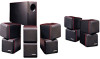
... the Acoustimass module to the left surround speaker. • The gray connector marked RS goes to the right surround speaker. Never use standard RCA cables to lengthen any connections turn off your system. The connectors have locating pins that assist you . Call Bose® customer service for ...gray connector marked LS goes to the left and right surround cube speakers. • The 20 foot (6 m) cable with five pairs of wires connects the Acoustimass module to the outputs on the cube speakers and are not intended for in making any of the supplied cables. The supplied cables are...
... the Acoustimass module to the left surround speaker. • The gray connector marked RS goes to the right surround speaker. Never use standard RCA cables to lengthen any connections turn off your system. The connectors have locating pins that assist you . Call Bose® customer service for ...gray connector marked LS goes to the left and right surround cube speakers. • The 20 foot (6 m) cable with five pairs of wires connects the Acoustimass module to the outputs on the cube speakers and are not intended for in making any of the supplied cables. The supplied cables are...

Owner's guide
Page 9
...surround decoding circuitry and amplified outputs for all RCA connectors are firmly inserted into the gray terminal on the left of wires to connect the Acoustimass module to the appropriate black (-) output. 3. a. b. c. Black connectors go into the LS and RS OUTPUT TO SPEAKER ... the polarity on the receiver: a. Gray connectors go to the Left Front SPEAKER OUTPUT connections. Gray C connector to -). Connect the wire pairs in place. 1. At the Acoustimass module, check to make sure the gray connectors are firmly inserted into C, LS, and RS jacks. Setting Up Connect the...
...surround decoding circuitry and amplified outputs for all RCA connectors are firmly inserted into the gray terminal on the left of wires to connect the Acoustimass module to the appropriate black (-) output. 3. a. b. c. Black connectors go into the LS and RS OUTPUT TO SPEAKER ... the polarity on the receiver: a. Gray connectors go to the Left Front SPEAKER OUTPUT connections. Gray C connector to -). Connect the wire pairs in place. 1. At the Acoustimass module, check to make sure the gray connectors are firmly inserted into C, LS, and RS jacks. Setting Up Connect the...

Owner's guide
Page 10
... (Figure 9). Be sure to + and - At the receiver, check that the wires are connected in a total loss of Acoustimass module output. Setting Up Check the connections Check all speakers are connected as front speakers.... L C R Figure 9 Completed connections FRONT SPEAKERS R L SURROUND SPEAKERS L REAR R CENTER LS RS OUTPUTS TO CUBE SPEAKERS L C R LS RS LEFT CENTER RIGHT LEFT RIGHT SURROUND SURROUND INPUTS FROM RECEIVER OR AMPLIFIER L C R LS RS 10...
... (Figure 9). Be sure to + and - At the receiver, check that the wires are connected in a total loss of Acoustimass module output. Setting Up Check the connections Check all speakers are connected as front speakers.... L C R Figure 9 Completed connections FRONT SPEAKERS R L SURROUND SPEAKERS L REAR R CENTER LS RS OUTPUTS TO CUBE SPEAKERS L C R LS RS LEFT CENTER RIGHT LEFT RIGHT SURROUND SURROUND INPUTS FROM RECEIVER OR AMPLIFIER L C R LS RS 10...


