Owner's guide
Page 37
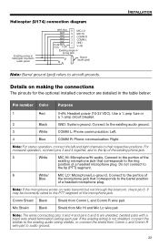
... Note: The wires connecting pins 3 and 4 and pins 5 and 6 are detailed in the table below: Pin number Color Purpose 1 Red V+IN: Headset power (10-32 VDC). Note: For stereo operation, connect the left and right channels to the existing audio ground. 3 White COMM L: Phone communication: ... L GND V+IN Existing single 4- English Tab 2, 10 Tab 3, 11 Tab 4, 12 Tab 5, 13 Tab 6, 14 Tab 7, 15 Tab 8, 16 INSTALLATION Helicopter (U174) connection diagram Existing wiring to audio ground. 33 prong jack Barrel (audio gnd) Note: Barrel ground (gnd) refers to the tip (PTT) segment....
... Note: The wires connecting pins 3 and 4 and pins 5 and 6 are detailed in the table below: Pin number Color Purpose 1 Red V+IN: Headset power (10-32 VDC). Note: For stereo operation, connect the left and right channels to the existing audio ground. 3 White COMM L: Phone communication: ... L GND V+IN Existing single 4- English Tab 2, 10 Tab 3, 11 Tab 4, 12 Tab 5, 13 Tab 6, 14 Tab 7, 15 Tab 8, 16 INSTALLATION Helicopter (U174) connection diagram Existing wiring to audio ground. 33 prong jack Barrel (audio gnd) Note: Barrel ground (gnd) refers to the tip (PTT) segment....


