Instruction Manual
Page 1
Bosch 20-inch High-resolution LCD Monitor UML-202-90 en Instruction Manual
Bosch 20-inch High-resolution LCD Monitor UML-202-90 en Instruction Manual
Instruction Manual
Page 3
... List 3 Exploded View 4 Remote Control 4.1 Remote Control Battery Installation 5 Description 5.1 Features 5.2 Power 6 6.1 6.2 6.2.1 6.2.2 6.3 6.4 6.5 6.5.1 6.6 6.6.1 6.6.2 6.6.3 6.7 Installing the UML-202-90 Ventilation Mounting the UML-202-90 Desktop Installation Wall Mount Installation Connecting the Composite Video Signal to the Monitor Connecting the Y/C (S-Video) Signal to the Monitor Connecting Audio to the... Display Menus 7.4 Custom Menu 7.5 Picture / Sound Menu 7.6 PIP Menu 7.7 Setup Menu 8 Power Management 8.1 Power Consumption Bosch Security Systems, Inc.
... List 3 Exploded View 4 Remote Control 4.1 Remote Control Battery Installation 5 Description 5.1 Features 5.2 Power 6 6.1 6.2 6.2.1 6.2.2 6.3 6.4 6.5 6.5.1 6.6 6.6.1 6.6.2 6.6.3 6.7 Installing the UML-202-90 Ventilation Mounting the UML-202-90 Desktop Installation Wall Mount Installation Connecting the Composite Video Signal to the Monitor Connecting the Y/C (S-Video) Signal to the Monitor Connecting Audio to the... Display Menus 7.4 Custom Menu 7.5 Picture / Sound Menu 7.6 PIP Menu 7.7 Setup Menu 8 Power Management 8.1 Power Consumption Bosch Security Systems, Inc.
Instruction Manual
Page 4
iv en | Table of Contents 8.2 LED Indicator 9 TroubleShooting Guide 10 Maintenance 11 Technical Specifications UML-202-90 26 27 28 29 F01U076723 | 1.0 | 2007.09 Instruction Manual Bosch Security Systems, Inc.
iv en | Table of Contents 8.2 LED Indicator 9 TroubleShooting Guide 10 Maintenance 11 Technical Specifications UML-202-90 26 27 28 29 F01U076723 | 1.0 | 2007.09 Instruction Manual Bosch Security Systems, Inc.
Instruction Manual
Page 5
UML-202-90 Table of Contents | en v Bosch Security Systems, Inc. Instruction Manual F01U076723 | 1.0 | 2007.09
UML-202-90 Table of Contents | en v Bosch Security Systems, Inc. Instruction Manual F01U076723 | 1.0 | 2007.09
Instruction Manual
Page 6
... switch is the main power disconnect device for switching off the voltage for ventilation to rain or moisture. 5. F01U076723 | 1.0 | 2007.09 Instruction Manual Bosch Security Systems, Inc. 1 en | Safety 1 1.1 UML-202-90 Safety Important Safety Instructions Read, follow, and retain for example near a bathtub, washbowl, sink, laundry basket, in a damp or wet basement, near...
... switch is the main power disconnect device for switching off the voltage for ventilation to rain or moisture. 5. F01U076723 | 1.0 | 2007.09 Instruction Manual Bosch Security Systems, Inc. 1 en | Safety 1 1.1 UML-202-90 Safety Important Safety Instructions Read, follow, and retain for example near a bathtub, washbowl, sink, laundry basket, in a damp or wet basement, near...

Instruction Manual
Page 7
... dangerous voltage or other hazards. 15. Instruction Manual F01U076723 | 1.0 | 2007.09 UML-202-90 Safety | en 2 - Servicing - Unauthorized substitutions may cause fire, electrical shock, or other hazards. Bosch Security Systems, Inc. For 24 VAC units, voltage applied to operate the equipment. ...12. User-supplied wiring must comply with applicable local codes. 17. Be sure the service technician uses replacement parts specified by Bosch, could void the warranty or, in performance; - unit does not operate normally when the user correctly follows the operating ...
... dangerous voltage or other hazards. 15. Instruction Manual F01U076723 | 1.0 | 2007.09 UML-202-90 Safety | en 2 - Servicing - Unauthorized substitutions may cause fire, electrical shock, or other hazards. Bosch Security Systems, Inc. For 24 VAC units, voltage applied to operate the equipment. ...12. User-supplied wiring must comply with applicable local codes. 17. Be sure the service technician uses replacement parts specified by Bosch, could void the warranty or, in performance; - unit does not operate normally when the user correctly follows the operating ...

Instruction Manual
Page 8
... This symbol indicates information or a company policy that relates directly or indirectly to the unit. 3 en | Safety 1.2 Safety precautions DANGER! UML-202-90 WARNING! Medium risk: ! If not avoided, this may result in an electrical shock, serious bodily injury, or death. If not avoided..., this could result in minor or moderate injury. F01U076723 | 1.0 | 2007.09 Instruction Manual Bosch Security Systems, Inc. High risk: This symbol indicates an imminently hazardous situation such as "Dangerous Voltage" inside the product. Indicates a potentially...
... This symbol indicates information or a company policy that relates directly or indirectly to the unit. 3 en | Safety 1.2 Safety precautions DANGER! UML-202-90 WARNING! Medium risk: ! If not avoided, this may result in an electrical shock, serious bodily injury, or death. If not avoided..., this could result in minor or moderate injury. F01U076723 | 1.0 | 2007.09 Instruction Manual Bosch Security Systems, Inc. High risk: This symbol indicates an imminently hazardous situation such as "Dangerous Voltage" inside the product. Indicates a potentially...

Instruction Manual
Page 9
... tripod, bracket, or mount. U.S.A. U.S. federal law strictly prohibits surreptitious recording of discharge unit, connection to replace the obsolete outlet. Bosch has a strong commitment towards the environment. Fuse rating - This safety feature allows the plug to fit into the outlet, contact a...to respect the environment as much as the main disconnect device for earth grounding). If unable to the unit. Bosch Security Systems, Inc. If unable to the unit. - UML-202-90 Safety | en 4 1.3 Important notices Accessories - All-pole power switch - i This device is used, ...
... tripod, bracket, or mount. U.S.A. U.S. federal law strictly prohibits surreptitious recording of discharge unit, connection to replace the obsolete outlet. Bosch has a strong commitment towards the environment. Fuse rating - This safety feature allows the plug to fit into the outlet, contact a...to respect the environment as much as the main disconnect device for earth grounding). If unable to the unit. Bosch Security Systems, Inc. If unable to the unit. - UML-202-90 Safety | en 4 1.3 Important notices Accessories - All-pole power switch - i This device is used, ...

Instruction Manual
Page 10
... the ISDN circuits are Safety Extra Low Voltage (SELV) circuits. To minimize the risk of lost digital information, Bosch Security Systems recommends multiple, redundant recording systems, and a procedure to the manufacturer's instructions. Disconnect the power before moving... SELV - 5 en | Safety UML-202-90 Moving - Incorporate a readily accessible disconnect device in which case the user may be held liable for all analog and digital information. Permanently connected equipment - Power lines - therefore, Bosch Security Systems cannot be required to the...
... the ISDN circuits are Safety Extra Low Voltage (SELV) circuits. To minimize the risk of lost digital information, Bosch Security Systems recommends multiple, redundant recording systems, and a procedure to the manufacturer's instructions. Disconnect the power before moving... SELV - 5 en | Safety UML-202-90 Moving - Incorporate a readily accessible disconnect device in which case the user may be held liable for all analog and digital information. Permanently connected equipment - Power lines - therefore, Bosch Security Systems cannot be required to the...

Instruction Manual
Page 12
...not cover the performance or reliability of the security or signaling aspects of Bosch Security Systems, Inc. Copyright This user guide is protected by copyright. All rights reserved. Bosch Security Systems accepts no liability for Information Technology Equipment, UL 60950-1. and.... The text was complete and correct at www.boschsecuritysystems.com F01U076723 | 1.0 | 2007.09 Instruction Manual Bosch Security Systems, Inc. 7 en | Safety UML-202-90 Disclaimer Underwriter Laboratories Inc. ("UL") has not tested the performance or reliability of the security or signaling ...
...not cover the performance or reliability of the security or signaling aspects of Bosch Security Systems, Inc. Copyright This user guide is protected by copyright. All rights reserved. Bosch Security Systems accepts no liability for Information Technology Equipment, UL 60950-1. and.... The text was complete and correct at www.boschsecuritysystems.com F01U076723 | 1.0 | 2007.09 Instruction Manual Bosch Security Systems, Inc. 7 en | Safety UML-202-90 Disclaimer Underwriter Laboratories Inc. ("UL") has not tested the performance or reliability of the security or signaling ...
Instruction Manual
Page 13
...800-366-2283 or 585-340-4162 Fax: 800-366-1329 Email: cctv.repair@us.bosch.com Customer Service Telephone: 800-289-0096 Fax: 585-223-9180 Email: security.sales@us.bosch.com Technical Support Telephone: 800-289-0096 Fax: 585-223-3508 or 717-735-6560... Fax: 44 (0) 1495 274280 Email: [email protected] More information For additional information, please contact your Bosch Security Systems representative or visit our web site at www.boschsecurity.com Bosch Security Systems, Inc. UML-202-90 1.4 Safety | en 8 Customer Support and Service If this unit needs service, contact the nearest...
...800-366-2283 or 585-340-4162 Fax: 800-366-1329 Email: cctv.repair@us.bosch.com Customer Service Telephone: 800-289-0096 Fax: 585-223-9180 Email: security.sales@us.bosch.com Technical Support Telephone: 800-289-0096 Fax: 585-223-3508 or 717-735-6560... Fax: 44 (0) 1495 274280 Email: [email protected] More information For additional information, please contact your Bosch Security Systems representative or visit our web site at www.boschsecurity.com Bosch Security Systems, Inc. UML-202-90 1.4 Safety | en 8 Customer Support and Service If this unit needs service, contact the nearest...
Instruction Manual
Page 14
... been damaged in the Parts List below are missing, notify your Bosch Security Systems Sales or Customer Service Representative. If an item appears to DVI-D cable, 1.5 m (5 ft) Remote control with care. If any items are included. Save it for service. UML-202-90 2 2.1 Unpacking | en 9 Unpacking This equipment should be used if returning the...
... been damaged in the Parts List below are missing, notify your Bosch Security Systems Sales or Customer Service Representative. If an item appears to DVI-D cable, 1.5 m (5 ft) Remote control with care. If any items are included. Save it for service. UML-202-90 2 2.1 Unpacking | en 9 Unpacking This equipment should be used if returning the...

Instruction Manual
Page 15
10 en | Exploded View 3 Exploded View UML-202-90 Fig. 3.1 Front Panel UML-202-90 Reference # Button 1 Input Button 2 Menu Button 3 Description Selects the signal to be displayed Selects the on-screen display (OSD) Adjusts the value when in the ... 7 IR Sensor Remote control sensor 8 LED Indicator Power On (green) Power Off, Standby (red) 9 Power Button Display power (On/Off) F01U076723 | 1.0 | 2007.09 Instruction Manual Bosch Security Systems, Inc.
10 en | Exploded View 3 Exploded View UML-202-90 Fig. 3.1 Front Panel UML-202-90 Reference # Button 1 Input Button 2 Menu Button 3 Description Selects the signal to be displayed Selects the on-screen display (OSD) Adjusts the value when in the ... 7 IR Sensor Remote control sensor 8 LED Indicator Power On (green) Power Off, Standby (red) 9 Power Button Display power (On/Off) F01U076723 | 1.0 | 2007.09 Instruction Manual Bosch Security Systems, Inc.

Instruction Manual
Page 16
... | en 11 1 2 3 4 5 6 7 9 8 10 11 12 13 14 15 16 17 18 Fig. 3.2 Side and Bottom Panels UML-202-90 Side Panel Reference # Connector 1 Video 1 (AV1) IN 2 Video 1 (AV1) OUT 3 Video 2 (AV2) IN 4 Video 2 (AV2) OUT 5 S-Video (Y/C) IN 6 S-Video (Y/C) OUT 7 Audio IN (AV1, S-Video) 8 Audio ... HDMI IN 13 DVI IN 14 D-SUB IN 15 PC Stereo IN 16 Audio OUT 17 Component Y, Pb, Pr and Sound L, R 18 DC 12 V IN Bosch Security Systems, Inc. Instruction Manual F01U076723 | 1.0 | 2007.09
... | en 11 1 2 3 4 5 6 7 9 8 10 11 12 13 14 15 16 17 18 Fig. 3.2 Side and Bottom Panels UML-202-90 Side Panel Reference # Connector 1 Video 1 (AV1) IN 2 Video 1 (AV1) OUT 3 Video 2 (AV2) IN 4 Video 2 (AV2) OUT 5 S-Video (Y/C) IN 6 S-Video (Y/C) OUT 7 Audio IN (AV1, S-Video) 8 Audio ... HDMI IN 13 DVI IN 14 D-SUB IN 15 PC Stereo IN 16 Audio OUT 17 Component Y, Pb, Pr and Sound L, R 18 DC 12 V IN Bosch Security Systems, Inc. Instruction Manual F01U076723 | 1.0 | 2007.09

Instruction Manual
Page 17
...Aspect Selects the screen ratio when in the OSD menus. Continuously press this button to change the ture Control) selection. UML-202-90 F01U076723 | 1.0 | 2007.09 Instruction Manual Bosch Security Systems, Inc. APC (Auto Pic- Continuously press this button to change the Color Control) selection. SET Selects the... button to change the selection. 12 en | Remote Control 4 Remote Control This section details the functions and the usage of the Bosch remote control. SOURCE Selects the PC or Video source. MUTE Mutes the sound. INPUT Selects the PC or Video source for the ...
...Aspect Selects the screen ratio when in the OSD menus. Continuously press this button to change the ture Control) selection. UML-202-90 F01U076723 | 1.0 | 2007.09 Instruction Manual Bosch Security Systems, Inc. APC (Auto Pic- Continuously press this button to change the Color Control) selection. SET Selects the... button to change the selection. 12 en | Remote Control 4 Remote Control This section details the functions and the usage of the Bosch remote control. SOURCE Selects the PC or Video source. MUTE Mutes the sound. INPUT Selects the PC or Video source for the ...

Instruction Manual
Page 18
Fig. 4.1 Battery Installation 3. Dispose of used batteries i properly. Bosch Security Systems, Inc. Instruction Manual F01U076723 | 1.0 | 2007.09 UML-202-90 4.1 Remote Control | en 13 Remote Control Battery Installation 1. Turn the remote over (buttons facing down) and push down on the cover and slide it off. 2. NOTICE! Replace batteries when required or at least once a year. Insert two (2) new AAA alkaline batteries, matching the batteries to the (+) and (-) marks inside the battery case. Slide the battery cover back into place.
Fig. 4.1 Battery Installation 3. Dispose of used batteries i properly. Bosch Security Systems, Inc. Instruction Manual F01U076723 | 1.0 | 2007.09 UML-202-90 4.1 Remote Control | en 13 Remote Control Battery Installation 1. Turn the remote over (buttons facing down) and push down on the cover and slide it off. 2. NOTICE! Replace batteries when required or at least once a year. Insert two (2) new AAA alkaline batteries, matching the batteries to the (+) and (-) marks inside the battery case. Slide the battery cover back into place.
Instruction Manual
Page 19
...pixels resolution has been designed to display Analog VGA and Composite Video signals. - 90 to accommodate the increasing use of PCs and digital video devices in CCTV systems. The UML-202-90 monitor includes two (2) looping Composite Video BNC connector inputs, two (2) looping Audio ... NTSC/PAL F01U076723 | 1.0 | 2007.09 Instruction Manual Bosch Security Systems, Inc. VGA Input - Composite Video Input - See Figure 3.1 on page 10 for front panel descriptions. 14 en | Description UML-202-90 5 5.1 5.2 Description The UML-202-90 20-inch (51-cm) Color Panel Display Monitor displays PAL...
...pixels resolution has been designed to display Analog VGA and Composite Video signals. - 90 to accommodate the increasing use of PCs and digital video devices in CCTV systems. The UML-202-90 monitor includes two (2) looping Composite Video BNC connector inputs, two (2) looping Audio ... NTSC/PAL F01U076723 | 1.0 | 2007.09 Instruction Manual Bosch Security Systems, Inc. VGA Input - Composite Video Input - See Figure 3.1 on page 10 for front panel descriptions. 14 en | Description UML-202-90 5 5.1 5.2 Description The UML-202-90 20-inch (51-cm) Color Panel Display Monitor displays PAL...
Instruction Manual
Page 20
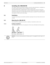
... openings on a desktop or mounted to 50°. Bosch Security Systems, Inc. UML-202-90 6 6.1 6.2 6.2.1 Installing the UML-202-90 | en 15 Installing the UML-202-90 This chapter outlines the procedures needed to fit the most comfortable monitoring status. Mounting the UML-202-90 The UML-202-90 is designed to be adjusted to install the UML-202-90 Series. For the best viewing quality and holding support...
... openings on a desktop or mounted to 50°. Bosch Security Systems, Inc. UML-202-90 6 6.1 6.2 6.2.1 Installing the UML-202-90 | en 15 Installing the UML-202-90 This chapter outlines the procedures needed to fit the most comfortable monitoring status. Mounting the UML-202-90 The UML-202-90 is designed to be adjusted to install the UML-202-90 Series. For the best viewing quality and holding support...
Instruction Manual
Page 21
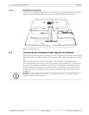
... 6.7 on page 19). To select between AV1 and AV2, press Input (see Figure 6.6 on page 19). F01U076723 | 1.0 | 2007.09 Instruction Manual Bosch Security Systems, Inc. 16 en | Installing the UML-202-90 UML-202-90 6.2.2 Wall Mount Installation The square mounting holes (100 mm (3.9 in.) centers) can be passed on to another monitor connected to it via...
... 6.7 on page 19). To select between AV1 and AV2, press Input (see Figure 6.6 on page 19). F01U076723 | 1.0 | 2007.09 Instruction Manual Bosch Security Systems, Inc. 16 en | Installing the UML-202-90 UML-202-90 6.2.2 Wall Mount Installation The square mounting holes (100 mm (3.9 in.) centers) can be passed on to another monitor connected to it via...
Instruction Manual
Page 22
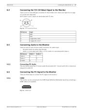
UML-202-90 6.4 Installing the UML-202-90 | en 17 Connecting the Y/C (S-Video) Signal to the monitor. Audio 2 is associated with 1/8 in. Connecting the PC Signal to the Monitor There are two (2) sets ... Definition Multimedia Input) by connecting a HDMI cable (not supplied). Instruction Manual F01U076723 | 1.0 | 2007.09 NOTE: Both Y and C inputs are active loop-through. - Fig. 6.3 HDMI Input Bosch Security Systems, Inc. Connect with Video 2. mini phono plug jack to Audio IN. Audio 1 is one (1) mini-DIN type connector for audio input. - Reference Video...
UML-202-90 6.4 Installing the UML-202-90 | en 17 Connecting the Y/C (S-Video) Signal to the monitor. Audio 2 is associated with 1/8 in. Connecting the PC Signal to the Monitor There are two (2) sets ... Definition Multimedia Input) by connecting a HDMI cable (not supplied). Instruction Manual F01U076723 | 1.0 | 2007.09 NOTE: Both Y and C inputs are active loop-through. - Fig. 6.3 HDMI Input Bosch Security Systems, Inc. Connect with Video 2. mini phono plug jack to Audio IN. Audio 1 is one (1) mini-DIN type connector for audio input. - Reference Video...
